Sollae Systems CSE-H21 User Manual
2 ports rs232 ethernet converter
Hide thumbs
Also See for CSE-H21:
- User manual (48 pages) ,
- User manual (50 pages) ,
- User manual (49 pages)

Related Manuals for Sollae Systems CSE-H21


Summary of Contents for Sollae Systems CSE-H21
- Page 1 2 Ports RS232 Ethernet Converter CSE-H21 User Manual Version 2.4 Sollae Systems Co., Ltd. http://www.ezTCP.com...
- Page 2 CSE-H21 User Manual Ver. 2.4 This symbol, found on your product or on its packaging, indicates that this product should not be treated as household waste when you wish to dispose of it. Instead, it should be handed over to an applicable collection point for the recycling of electrical and electronic equipment.
-
Page 3: Table Of Contents
2.1.3 Configuring the Environmental Variables ................... - 14 - 2.2 Test Run ................................- 14 - 2.2.1 Changing PC IP Address ........................- 14 - 2.2.2 Installing CSE-H21 ..........................- 14 - 2.2.3 Configuring CSE-H21 ........................... - 14 - 2.2.4 Communication Test ..........................- 16 - Configuration ........................ - Page 4 Security Protocols & Option ..................... - 41 - 6.1 SSL ..................................- 41 - 6.1.1 SSL (Secure Socket Layer) ........................- 41 - 6.1.2 How to set the SSL on CSE-H21 ....................- 41 - http://www.ezTCP.com Sollae Systems Co., Ltd.
- Page 5 6.1.3 Restriction..............................- 42 - 6.2 SSH ..................................- 42 - 6.2.1 SSH (Secure Shell) ..........................- 42 - 6.2.2 How to set the SSH on CSE-H21 ....................- 42 - 6.2.3 Restriction..............................- 43 - 6.3 ezTCP Firewall ..............................- 44 - Related material ........................
-
Page 6: Overview
LAN after TCP/IP processing and vice versa. As CSE-H21 has 2 RS232 ports, it can be connected to two RS232 devices in the same time. And it is easy CSE-H21 to attach to user systems because of its compact size. -
Page 7: Specification
CSE-H21 User Manual Ver. 2.4 1.3 Specification 1.3.1 Hardware Input Voltage DC 5V (±10%) Power Current 270mA typical Dimension 158mm x 90mm x 24mm Weight About 340g Arm7 Core 2 × RS232 – RTS/CTS Flow Control Serial (Baud rate: 300bps ~ 230,400bps) -
Page 8: Layout
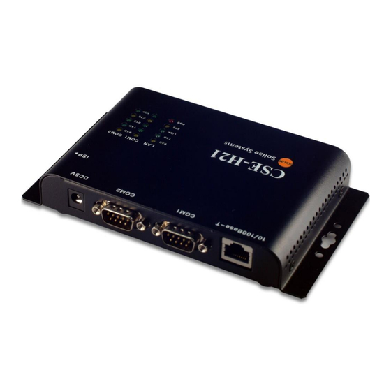
1.4.1 Layout There are an Ethernet port, two RS232 ports, and a Power socket on the top side. And there is an ISP switch on the right side. And 15 LED indicators are in the CSE-H21. Figure 1-1 CSE-H21 Layout http://www.ezTCP.com... -
Page 9: Led Indicators
CSE-H21 User Manual Ver. 2.4 1.4.2 LED indicators There are 15 LED indicators on the CSE-H21. The left 5 are for LAN status, and the middle and right 5 are for COM1 and COM2 respectively. The followings are the operations of each LED indicators. -
Page 10: Interface
Table 1-3 RS232 Parameters Items Parameters Data bit 8, 7, 6, 5 Parity None, Even, Odd, Mark, Space Stop bit 1, 1.5, 2 Flow Control CSE-H21 supports RTS/CTS Hardware Flow Control. http://www.ezTCP.com Sollae Systems Co., Ltd. - 9 -... - Page 11 DTR, Baud rate, data bits, parity, stop bit) after getting information from the communication counterpart. Disable TCP Transmission Delay If you use this option, CSE-H21 sends the data from the serial port to Ethernet as quickly as possible. TX Delay CSE-H21 has a function that delays its serial data for the user’s slow device.
-
Page 12: Ethernet Interface
CSE-H21 User Manual Ver. 2.4 1.5.2 Ethernet Interface Network part of CSE-H21 is configured with Ethernet. So, what you have to do is only to connect UTP cable. The Ethernet part detects 10Mbit or 100Mbit Ethernet automatically, to connect the corresponding cable. It also provides auto MDI/MDIX function to detect 1:1 cable or cross-over cable automatically. -
Page 13: Power
CSE-H21 User Manual Ver. 2.4 1.5.3 Power DC5V is used for CSE-H21 and the specification is below: Figure 1-4 DC 5V Power Jack http://www.ezTCP.com Sollae Systems Co., Ltd. - 12 -... -
Page 14: Getting Start
IP address environment (local IP, subnet mask, gateway, DHCP/PPPoE etc.) Serial port type of the equipment to which CSE-H21 is going to be connected (RS232) Serial port items of the equipment to which CSE-H21 is going to be connected (baud rate, data bit, parity, stop bit, flow control) ... -
Page 15: Configuring The Environmental Variables
Connect the supplied RS232 cable between your PC and CSE-H21, the LAN cable to the hub to which the PC is connected or directly to the PC, and the supplied CSE-H21 power adapter to CSE-H21 for power supply. If the LAN cable has been correctly connected when power is supplied, LINK LED turns on. - Page 16 CSE-H21 User Manual Ver. 2.4 For simple test, we recommend that the variables keep default values as shown in the below table. Parameter Value Local IP Address 10.1.0.1 Network Subnet Mask 255.0.0.0 Telnet Enabled Option IP Address Search Enabled Serial Type...
-
Page 17: Communication Test
CSE-H21 User Manual Ver. 2.4 2.2.4 Communication Test Power the CSE-H21 off and on, then it tries to connect to the LAN. A program for testing starts if you press the [Simple Test] button of the ezManager. Press the [Connect] button after inputting 10.1.0.1 and 1470 in the IP and Port. If the TCP connection is established there will be “Connected [10.1.0.1: 1470]. - Page 18 CSE-H21 User Manual Ver. 2.4 Press the [Open] button after selecting serial port that is connected to the CSE-H21. If the serial port is open, the “COM1 the COM port has opened” message will be shown. If you press the [Send Data] button on the LAN part (Top), the data shown in the [Send] box will be transmitted to the [Receive] box on the RS232 part (Bottom).
- Page 19 CSE-H21 User Manual Ver. 2.4 If you press the [Send Data] button on the RS232 part (Bottom), the data shown in the [Send] box will be transmitted to the [Receive] box on the LAN part. If the transmitting and receiving data are same, the communication test is successful.
-
Page 20: Configuration
CSE-H21. You can set the IP address and the serial port related items by using ezManager, the supplied configuration utility which allows you to configure your CSE-H21 over the network, or by using AT commands in ATC mode 3.2 Configuring with ezManager... -
Page 21: Buttons Of Ezmanager
CSE-H21 User Manual Ver. 2.4 3.2.2 Buttons of ezManager Button Description Read Read the values configured through MAC or IP address. Write Store the changed values of parameters Set Password Set or remove the password by this button. Status Check the status of ezTCP in real time. -
Page 22: Matters To Be Attended To
3.4.1 DDNS (Dynamic Domain Name System) If the CSE-H21 obtains its IP address, it notices to the service provider. Then the service provider serves DNS service. So, even though user doesn’t know the CSE-H21’s IP address, user can connect to the CSE-H21 by the host name (after DNS looking up.) The DDNS service provider that the CSE-H21 supports is only DynDNS (http://dyn.com/dns/) currently. -
Page 23: Tcp/Udp
CSE-H21 User Manual Ver. 2.4 3.4.2 TCP/UDP In addition, CSE-H21 can transmit some information to user’s TCP/UDP servers each period which is set. This information is IP address, MAC address, product ID, firmware version, and comment. The data can be sent as either ASCII or Hexadecimal type. -
Page 24: System Management
CSE-H21 User Manual Ver. 2.4 System Management 4.1 Operation Mode CSE-H21 can operate in one of two modes (normal and ISP modes). Normal mode is ordinary data communication mode; and ISP mode is used to download CSE-H21 firmware through the Ethernet port. -
Page 25: Upgrading Firmware
Supply power with pressing ISP button or push the button over 1 second, then CSE-H21 operates in the ISP mode. Run hotflash that is supplied by us and input IP address of CSE-H21 and select the firmware with the [FILE] menu. Then, send it with [SEND] button. (Uncheck the [Verify firmware version] option.) -
Page 26: Checking Current Status
4.3 Checking current status 4.3.1 Telnet login You can log in the CSE-H21 if you enable the [Telnet option] in the [OPTION] tab of the ezManager. Then you can check the network and serial status after logging in the CSE-H21. - Page 27 Serial Ports I/O data capture This command is available on 1.2H or subsequently released firmware version. User can monitor the input / output data of CSE-H21’s serial ports with the “sd” command. The way of using this command is like below.
-
Page 28: Check Status In The Ezmanager
CSE-H21 User Manual Ver. 2.4 4.4 Check Status in the ezManager If you press the [STATUS] in the ezManager, you can monitor the current status of CSE- H21. If user sets [Refresh Every 1 second] option, the status data will be updated in every second. -
Page 29: Remote Debugging
UDP port 50006. Then user can get the messages with new window if user presses [Debugging Message] button as followed: This function is very useful when there are any problems when users install the CSE-H21 in the user site. -
Page 30: Communication Mode
Communication Mode 5.1 Introduction Normal communication mode is suitable for the purpose of using CSE-H21. Normal communication mode can be classified into four modes – T2S, ATC, COD, and U2S – each of which is described in the following table. -
Page 31: T2S - Tcp Server
[Event Byte] settings. If the [Event Byte] is 0, the data that comes to serial port of CSE-H21 will not be recognized. If it is not 0, the serial data before TCP connection will be temporarily saved to be sent to the host after the connection. -
Page 32: Disconnection
CSE-H21 User Manual Ver. 2.4 seconds, so CSE-H21 rounds down rest of the values. 5.2.4 Disconnection When the connected host terminates the connection, or there is no data communication during the designated [Timeout], the TCP connection will be automatically terminated. The unit used for [Timeout] is 1 second. -
Page 33: Cod - Tcp Client
Data before TCP connection will be handled based on the [Event Byte] settings. If the [Event Byte] is 0, the data that comes to CSE-H21’s serial port will not be recognized. If it is not 0, the serial data before TCP connection will be temporarily saved to be sent to the host after the connection. -
Page 34: Disconnection
[Timeout] is 1 second. 5.3.4 DNS If users set the host name instead of the IP address on the [Peer Address] box, CSE-H21 query the IP address of the host to its Domain Name Server (DNS). The IP address of DNS can be configured on ezManager. -
Page 35: Atc - At Command
CSE-H21 User Manual Ver. 2.4 5.4 ATC – AT Command AT command is a mode which users control CSE-H21 with AT command like controlling modem. In this mode, active and passive TCP connections are available. And users are allowed to configure some environmental parameters with extended commands. -
Page 36: Examples
Processes of TCP connection ③ TCP connection has been established CSE-H21 sends “CONNECT” message to the serial port Most of the response messages from the serial port of CSE-H21 are omitted on above figure. http://www.ezTCP.com Sollae Systems Co., Ltd. - Page 37 Figure 5-2 TCP Active connection Table 5-3 states of each point Points States Set parameters in the AT command mode CSE-H21 sends a TCP connection request with the ATD ① command Processes of TCP connection ② TCP connection has been established CSE-H21 sends “CONNECT”...
- Page 38 TCP connection has been terminated CSE-H21 sends “NO CARRIER” with disconnection CSE-H21 changes the mode to AT command, when receiving “+++” and sending “OK” message. In this state, the communication with remote host is not possible because CSE- H21 processes only AT command. Whenever you want to go back to online state (TCP connection), use “ATO”...
-
Page 39: Udp
CSE-H21 User Manual Ver. 2.4 5.5 UDP UDP has no processes of connection. In this mode, data is sent in block units. Therefore, data that comes through CSE-H21’s serial port must be classified in block units to send it elsewhere. 5.5.1 Key parameters ... -
Page 40: Examples
Points States CSE-H21 is receiving data from the serial port ① CSE-H21 Sends 5 bytes as one block based on the [Block Size] Serial device sends data “678” to the CSE-H21 ② Data “678” has arrived CSE-H21 sends data from the remote host to the serial device ③... - Page 41 Remote host 2 sends data again to CSE-H21 ③ CSE-H21 updates host 2 to peer host CSE-H21 can communicate with remote host 2 The data “ABC”, “DE”, “FGH” are from the serial port of CSE-H21 in the Fig 5-5. http://www.ezTCP.com Sollae Systems Co., Ltd.
-
Page 42: Security Protocols & Option
Set the [SSL] check box in the ezManager. Log in the CSE-H21 with telnet client. Generate an RSA key with a command. CSE-H21 supports 512, 768, and 1024 length keys. Command Format : rsa keygen [key length] http://www.ezTCP.com... -
Page 43: Restriction
Save the parameters for SSL with the ‘ssl save aa55cc33’ command. 6.1.3 Restriction To use the SSL with CSE-H21, there is a restriction. You can use only one serial port (COM1) if you set the SSL function. 6.2 SSH 6.2.1 SSH (Secure Shell) -
Page 44: Restriction
Save the parameters for SSH with a ‘ssh save aa55cc33’ command. 6.2.3 Restriction To use the SSH function with CSE-H21, there is a restriction. You can use only T2S mode (TCP Server mode) if you set the SSH function http://www.ezTCP.com... -
Page 45: Eztcp Firewall
All security functions are disabled in the ISP mode. So user can access the CSE- H21 in the ISP mode even though user can’t access the CSE-H21 in the normal mode because of the [ezTCP Firewall] function. http://www.ezTCP.com Sollae Systems Co., Ltd. -
Page 46: Related Material
CSE-H21 User Manual Ver. 2.4 Related material Technical Documents You can find the technical documents at our website. DataSheet IP Change Notification (DDNS) How to use SSL How to use SSH Sending MAC Address function ... -
Page 47: Technical Support And Warranty
Technical Support and Warranty Technical Support If you have any question regarding operation of the product, visit Customer Support FAQ corner and the message board on Sollae Systems’ web site or send us an email at the following address: E-mail: support@eztcp.com... -
Page 48: Precaution And Exemption From Liability
Do not use the product for a purpose that requires exceptional quality and reliability relating to user’s injuries or accidents – aerospace, aviation, health care, nuclear power, transportation, and safety purposes. Sollae Systems is not responsible for any accident or damage occurring while using the product. http://www.ezTCP.com Sollae Systems Co., Ltd. -
Page 49: Exemption From Liability
Sollae Systems Co., Ltd. and its distributors entire liability and your exclusive remedy shall be Sollae Systems Co., Ltd. and its distributors option for the return of the price paid for, or repair, or replacement of the CSE-H21. - Page 50 à caractère commercial ou de toute autre perte financière) provenant de l'utilisation ou de l'incapacité à pouvoir utiliser le boîtier CSE-H21, même si Sollae Systems Co., Ltd. ou un de ses distributeurs a été informé de la possibilité de tels dommages.
- Page 51 CSE-H21 sans que la responsabilité de Sollae Systems Co., Ltd. et de ses distributeurs ne puissent être mise en cause, ni que le boîtier CSE-H21 puisse être échangé au titre de la garantie.
-
Page 52: Revision History
CSE-H21 User Manual Ver. 2.4 10 Revision History Date Ver. Comments Author Jun. 03. 2008 ○ Initial Release ○ Add SSL and SSH functions Aug. 01. 2008 ○ Add WEEE notation ○ Modify ISP button function ○ Add AT+PNIP, AT+PRHN Dec. - Page 53 CSE-H21 User Manual Ver. 2.4 ○ Update a screenshot of ezManager. Jan.11.2012 about service using of DynDNS has been Peter ○ Caution added ○ Descriptions of FIFO function has been deleted. June.18.2012 ○ Extend the warranty period to two years Peter ○...
Need help?
Do you have a question about the CSE-H21 and is the answer not in the manual?
Questions and answers