
Related Manuals for Sonic Driver UFM-300


Summary of Contents for Sonic Driver UFM-300
- Page 1 Made in Britain Ultrasonic Clamp-on Flowmeter UFM-300 Laptop Installation Manual Version 1.0 July 2024 Copyright Sonic Driver Ltd 2024...
-
Page 2: Table Of Contents
Contents 1.0 Introduction • 1.1 Transit Time Measurement • 1.2 Packing List • 1.3 General Precautions • 1.4 Cleaning 2.0 Mounting the UFM and its Flow Transducers • 2.1 Guide-rail mounting • 2.2 Pipe mounting • 2.3 Wall mounting • 2.4 Panel mounting 3.0 Installing and Using the Laptop Configuration Program •... - Page 3 9.0 Service 10.0 Limited Warranty and Disclaimer Appendix A Contact Details Appendix B Table of typical pipe roughness values Appendix C Error codes...
-
Page 4: Introduction
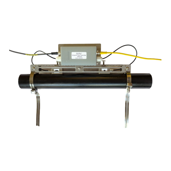
Congratulations on choosing the Sonic Driver Ultrasonic Flowmeter UFM-300, guide-rail, pipe, wall or panel mounted clamp-on ultrasonic flowmeter, figure (1). Figure (1) The Sonic Driver UFM-300. The UFM uses advanced Digital Signal Processing (DSP) and transit time measurement techniques (Sonic Driver ) to make accurate and reliable clamp-on ultrasonic flow velocity measurements on liquids flowing in closed pipes. - Page 5 For installation a laptop is connected to the UFM via a bidirectional USB to RS485 converter. All installation parameters are available for editing locally via the laptop or remotely over Modbus RTU. The UFM comes in 2 different versions; • Standard - outer pipe diameter ranged 10.0 to 115.0 mm •...
-
Page 6: Transit Time Measurement
1.1 Transit Time Measurement The principle of flow measurement using ultrasonic clamp-on transit time measurement is simple, see figure (2). Figure (2) The principle of transit time flow measurement. Two ultrasonic transducers are coupled or clamped to the outside of the pipe at a predetermined distance apart. -
Page 7: Packing List
1.3 General Precautions The content of this manual has been carefully checked and is believed to be accurate. Sonic Driver Ltd assumes no responsibility for any inaccuracies that may be contained in this manual. In no event will Sonic Driver be liable for direct, indirect, special, incidental or consequential damages resulting from any defect or omission in this manual, even if we are advised of the possibility of such damages. -
Page 8: Mounting The Ufm And Its Flow Transducers
2.0 Mounting the UFM and its Flow Transducers The UFM and its transducers can be physically installed in 4 different configurations: 2.1 Guide-rail mounting Mount the guide-rail on the pipe using cable ties (small pipes) or metal banding (large pipes), see figure (3). - Page 9 Figure (5) Pipe mounting bracket attached with metal banding, transducers attached with cable ties. When making the installation select banding or cable ties as appropriate. Figure (6) Detail showing position of banding and cable ties. Note the position of the tab on the mounting plate, over which the banding passes.
-
Page 10: Wall Mounting
Figure (7) Pipe mounting with UFM removed for clarity of mounting tabs. Figure (7) is for clarity only; it is not recommended to remove the UFM. 2.3 Wall mounting Mount the flow transducers on the pipe using cable ties (small pipes) or metal banding (large pipes), see figure (8, 9). -
Page 11: Panel Mounting
Figure (9) Wall mounting tabs. 2.4 Panel mounting Mount the flow transducers on the pipe using cable ties (small pipes) or metal banding (large pipes) as in section 2.3, figure (8). Screw or bolt the UFM mounting plate inside the panel. When measuring the spacing of the transducers, note that spacing is measured between the front faces of the transducers, see figure (10). - Page 12 Figure (11) Misaligned transducers. Figure (12) Twisted transducers. Ensure that the arrow on the labels (arrowhead and flights) on the flow transducers is pointing in the direction of flow. Use coupling gel between the transducers and the pipe to give good ultrasonic contact.
-
Page 13: Installing And Using The Laptop Configuration Program
3.0 Installing and Using the Laptop (Windows) Configuration Program 3.1 Installation Create a folder on the laptop drive, typically named C:\UFM Download or copy the installation program from the supplied media to the folder. If supplied in zip format, then unzip the file into the folder. Locate and run the setup.exe program. - Page 14 Click the Find Com button, see figure (14). Figure (14) Connect to the UFM A list of available com ports will be shown. Highlight the com port associated with the USB/RS485 converter in use by clicking on the list, it will highlight in blue. To identify the com port use Windows Device Manager.
- Page 15 Figure (15) Default Parameter Values. Most importantly the Company, Model, serial number and hardware and software version of the UFM will be read and displayed. The user is also guided with a link to the associated Smart device App online if not already aware. Now press the Read Meter Setup button, the configuration program will read the actual setup of the UFM, which will be different to the factory defaults if the UFM has previously been programmed with different values, see figure (16).
-
Page 16: Configuring The Ufm
Figure (16) Read Meter Setup. The configuration program reads and displays the ultrasonic signal being measured. The first arrival of the signal should appear in the blue square, the green line indicates where the UFM has determined the first arrival to be. If the UFM is not confident then this line will be red. Flow measurement and diagnostics are shown in the relevant text boxes on the dashboard. - Page 17 Figure (17) Quick Start Parameters. Parameters and settings in the UFM can be edited by; • Selecting an item using a scrolling list • Ticking a Tick Box • Direct numerical entry It is important to note that after direct numerical entry of a parameter value it is important to press the named button next to the entry for it to be checked against limits, entered and saved.
-
Page 18: Other Communication Software
To read a previously configured UFM configuration press the Read Meter Settings button. To make flow measurements continue to press the Read Meter Settings button. For more details on using the dashboard read the Operating Instructions manual that accompanies this Installation Manual. 3.4 Other Communication Software For experienced users of Modbus RTU there are several communications programs available for download online. -
Page 19: Transducer Menu
• DM10 (Default) • DM20 • DS10 DM sensors are Sonic Driver standard PEEK/stainless steel design. DN sensors are Sonic Driver small pipe design. DS sensors are for larger diameter pipes. 4.1.2 Number of Passes The user is prompted to enter the number of times the sound path crosses the pipe. Allowed values are 1 to 16. - Page 20 Figure (20) 2 passes. • 3 passes, used on small diameter pipes. • 4 passes, used on the smallest diameter pipes, see figure (21). Figure (21) 4 passes. • 5 to 15 and 16, etc. It may be that on the smallest diameter pipes then the recommended transducer spacing at 16 passes is not sufficient to allow the transducers to be coupled on the same side of the pipe, using an even number of passes as they still touch.
-
Page 21: Pipe Menu
4.2 Pipe Menu The following parameters allow the user to specify the pipe. 4.2.1 Material The user can select the pipe material from a list; • Carbon Steel • Stainless Steel • Copper • PVC (Default) • Cast Iron • Ductile Iron •... -
Page 22: Temperature
4.4.2 Temperature The user is prompted to enter the temperature of the fluid in the pipe. Allowed values are ranged -20 to +150 deg C, default 18 deg C. Changing Fluid Temperature causes Fluid Sound Velocity, Fluid Kinematic Viscosity and Fluid Density to be recalculated. -
Page 23: Sensor Positioning
5.0 Sensor Positioning Using the entered parameters, the UFM calculates and gives the required transducer spacing on the pipe under diagnostics. The user is then presented with a sensor positioning screen and diagnostics showing, • Graph of received ultrasonic signal •... -
Page 24: Optimising Transducer Mounting Location
Figure (24) Non-ideal Sensor Positioning, transducers too close together. ATA/ETA will be greater than 100 %. In figure (23) the received signal is too far to the right, the user should slide the transducers closer together. In figure (24 the received signal is too far to the left; the user should slide the transducers further apart. -
Page 25: Upstream And Downstream Pipe Runs
• Composite pipes can have de-laminations in their wall thickness, this type of pipe is notoriously bad when installing a UFM. • Ensure the temperature at the transducer location is within the transducers rated range. • Ideally the fluid should be free of particulates and bubbles, in the limit then an alternative method such as Doppler flow measurement may be required. -
Page 26: Transducer Spacing
Banding or clamping is required to keep the transducers in place. It is recommended to use 10 mm wide jubilee clips. Plastic cable ties are also an option as long as transducer alignment can be maintained. 5.4 Transducer Spacing Given that all information regarding the installation has been entered accurately and the advice above has been followed then the UFM will measure reliably and accurately. - Page 27 • Full set of measured values and instrument and measurement diagnostics available over Modbus RTU RS485. • Signal oscilloscope for sensor positioning and diagnostics. • Internal database of pipe and fluid materials. • Fluid database of sound speed, density and viscosity compensated for fluid temperature. •...
- Page 28 Transducers Figure (26) PEEK/stainless steel transducers. • DM10 sensors cover the range of pipe outer diameter 10 to 225 mm. • Material stainless steel and PEEK. • Temperature range -10 to +80 deg C. • Ingress Protection rated IP54, with IP68 option. •...
-
Page 29: Product Identification
10.0 Limited Warranty and Disclaimer Sonic Driver Ltd warrants to the end purchaser, for a period of one year from the date of shipment from our factory, that all new products manufactured by it are free from defects in materials and workmanship. - Page 30 No agent or representative of Sonic Driver Ltd has any authority to alter the terms of this warranty in any way. Appendix A Contact Details Telephone: +44(0)7971 273000 Postal Address: Sonic Driver Ltd, Lochiel, Llaneilian Road, Amlwch, Gwynedd, LL68 9HU, UK.
- Page 31 • 9 Spare • 10 Spare • 11 Spare • 12 Spare • 13 Spare • 14 Spare • 15 Spare Spare bits are always 0. Sonic Driver...
Need help?
Do you have a question about the UFM-300 and is the answer not in the manual?
Questions and answers