
Related Manuals for Sonic Driver POCKET-UFM


Summary of Contents for Sonic Driver POCKET-UFM
- Page 1 Made in Britain POCKET-UFM Ultrasonic Flowmeter Installation Manual Version 4.0 13th March 2023 Copyright Sonic Driver Ltd 2023...
-
Page 2: Table Of Contents
Contents 1.0 Introduction • 1.1 Transit Time Measurement • 1.2 Packing List • 1.3 General Precautions • 1.4 Cleaning • 1.5 Storage • 1.6 Fitting/Changing Internal Battery • 1.7 Connecting The Flow Transducers • 1.8 Mounting The Flow Transducers • 1.9 Turning the UFM On 2.0 Using the Quick Start Sequence •... - Page 3 Appendix A Contact Details Appendix B Table of fluid properties Appendix C Table of pipe and lining material properties Appendix D Table of speed of sound in water Appendix E Table of typical pipe roughness values...
-
Page 4: Introduction
1.0 Introduction Congratulations on choosing the Sonic Driver POCKET-UFM clamp-on ultrasonic flowmeter, figure(1). Figure(1) The Sonic Driver POCKET-UFM. The ultrasonic flowmeter (UFM) uses advanced Digital Signal Processing (DSP) and transit time measurement techniques (Sonic Driver ) to make accurate and reliable clamp-on ultrasonic flow velocity measurements on liquids flowing in closed pipes. -
Page 5: Transit Time Measurement
1.1 Transit Time Measurement The principle of flow measurement using ultrasonic clamp-on transit time measurement is simple, see figure(2). Figure(2) The principle of transit time flow measurement. Two ultrasonic transducers are coupled or clamped to the outside of the pipe at a predetermined distance apart. -
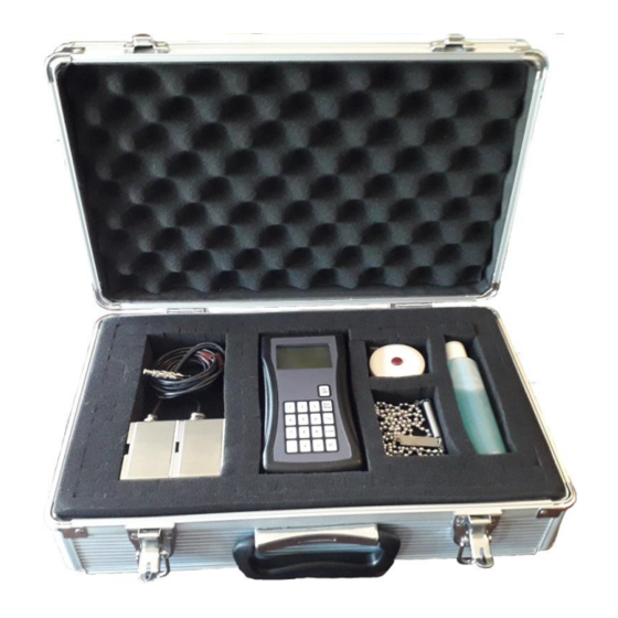
Page 6: Packing List
1.2 Packing List Figure(3) UFM Carry Case and Contents. Within the UFM carry case, see figure(3) you should find; Item Quantity POCKET-UFM PEEK/Stainless Steel Flow Transducer Wall Thickness (WTG) Probe Optional Chain Mounting Clamp Tape Measure Coupling Gel Battery Table(1) Packing List. -
Page 7: General Precautions
Sonic Driver Ltd assumes no responsibility for any inaccuracies that may be contained in this manual. In no event will Sonic Driver Ltd be liable for direct, indirect, special, incidental or consequential damages resulting from any defect or omission in this manual, even if we are advised of the possibility of such damages. -
Page 8: Connecting The Flow Transducers
Figure(4) Battery compartment. Lower capacity or use of rechargeable battery will decrease the run time of the UFM. 1.7 Connecting The Flow Transducers Connect the flow transducers to the Lemo connectors at the top of the UFM, see figure(5). Figure(5) Flow transducer connection. Red flow transducer is mounted on the pipe downstream, black flow transducer is mounted upstream. -
Page 9: Mounting The Flow Transducers
1.8 Mounting The Flow Transducers Mount the flow transducers on the pipe using the chain clamps supplied, see figure(6). Ensure that the arrow on the labels (arrowhead and flights) on the flow transducers is pointing in the direction of flow. Use coupling gel between the transducers and the pipe to give good ultrasonic contact. -
Page 10: Turning The Ufm On
1.9 Turning the UFM On To power on a POCKET-UFM press and hold the On key. As soon as the UFM is switched on a self-diagnostic program will start. This program fully tests both the UFM hardware and software. -
Page 11: Using The Quick Start Sequence
2.0 Using the Quick Start Sequence Once powered on the UFM will be in UI mode displaying the Main Menu. The Main Menu allows the user to select a group of parameters to edit or a meter function; • Quick Start •... -
Page 12: Transducer Menu
• Flow Other • WTG DM sensors are Sonic Driver standard PEEK/stainless steel design. DN sensors are Sonic Driver small pipe design. DS sensors are Sonic Driver large pipe design. If Flow Other is selected then the user will be prompted to enter detailed transducer specific information. - Page 13 • • • • Selecting Auto means that the UFM determines for itself which sound path to use. Ideally choose a number of passes that results in a path length in the fluid of 100mm or greater. • Z or 1 pass, most common on large diameter pipes, typically 100mm or more in diameter. If the UFM suggests a negative spacing then this is measured as in figure(9).
- Page 14 • N or 3 passes, used on small diameter pipes. • W or 4 passes, used on the smallest diameter pipes, see figure(11). Figure(11) W or 4 passes. • 5 to 11 and 12, etc. It may be that on the smallest diameter pipes then the recommended transducer spacing at 12 passes is not sufficient to allow the transducers to be coupled on the same side of the pipe, using an even number of passes as they still touch.
-
Page 15: Pipe Menu
2.2 Pipe Menu The following parameters allow the user to specify the pipe. 2.2.1 Outer Diameter The user is prompted to enter a value for the pipe outer diameter. Allowed values are ranged 10.0 to 6500.0mm, default 60.6mm. 2.2.2 Wall Thickness The user is prompted to enter a value for the pipe wall thickness. -
Page 16: Liner Menu
2.3 Liner Menu This menu allows the user to change pipe lining settings. 2.3.1 Material The user can select a pipe liner material from a list; • None (Default) • Cement • Epoxy • Glass • PP • Teflon • Rubber •... -
Page 17: Fluid Menu
2.4 Fluid Menu This menu allows the user to change fluid settings. 2.4.1 Type The user can select the fluid in the pipe from a list; • Water (Default) • Sea Water • Kerosene • Petrol • Fuel Oil • Crude Oil •... -
Page 18: Sensor Positioning
3.0 Sensor Positioning After completing entry of all parameters in the Quick Start function sequence the user is prompted to confirm Transducer Type and is then taken to the Sensor Positioning screen. Using the entered parameters the UFM calculates and gives the required transducer spacing on the pipe. -
Page 19: Optimising Transducer Mounting Location
Figure(14) Non-ideal Sensor Positioning, transducers too close together. In figure(13) the received signal is too far to the right, the user should slide the transducers closer together. In figure(14) the received signal is too far to the left, the user should slide the transducers further apart. -
Page 20: Upstream And Downstream Pipe Runs
• Ideally the fluid should be free of particulates and bubbles, in the limit then an alternative method such as Doppler flow measurement may be required. • Pipe linings that are not bonded properly or are not conductive of ultrasound (rubber) will cause measurement problems. -
Page 21: Transducer Spacing
chain clamp supplied or 10mm wide jubilee clips. 3.4 Transducer Spacing Given that all information regarding the installation has been entered accurately and the advice above has been followed then the UFM will measure reliably and accurately. This is confirmed by, •... -
Page 22: Battery Life
Figure(16) Laminar (a) and turbulent (b) flow. 6.0 Battery Life The POCKET-UFM is powered by a single high capacity 9Vdc PP3 primary cell 1200mAh. Under normal operating conditions the battery life of the UFM is in excess of 12 hours continuous measurement. -
Page 23: Specification
7.0 Specification The UFM has the following specification, features and performance; • Pipe outer diameters ranging from 10 to 6500 mm. • Temperature range for pocket meter -10 to +65 degC. • Weight 230 g (including internal PP3 battery). • Dimensions 185 x 85 x 25 mm. •... - Page 24 Transducers Figure(17) PEEK/stainless steel transducers. • 3 operating frequencies to cover the range of pipe outer diameter 10 to 6500mm. • DM10, 1MHz for pipes of 25mm to 750mm. • DS10, 1MHz for pipes of 50mm and over. • DM20, 2MHz for pipes less than 25mm. •...
-
Page 25: Product Identification
10.0 Limited Warranty and Disclaimer Sonic Driver Ltd warrants to the end purchaser, for a period of one year from the date of shipment from our factory, that all new products manufactured by it are free from defects in materials and workmanship. - Page 26 No agent or representative of Sonic Driver Ltd has any authority to alter the terms of this warranty in any way.
- Page 27 Appendix A Contact Details Telephone: +44(0)7971 273000 Postal Address: Sonic Driver Ltd, Lochiel, Llaneilian Road, Amlwch, Gwynedd, LL68 9HU, UK. Email: service@sonic-driver.com Website: www.sonic-driver.com Appendix B Table of fluid properties Fluid Longitudinal Speed of Sound (m/s) Water 20 (degC) 1482...
- Page 28 Galvanized Iron 0.15 Asphalted Cast Iron 0.12 Commercial or Welded Steel 0.045 PVC, Glass and other drawn tubing 0.0015 By default the Sonic Driver flowmeter uses a figure of 0.01mm as a good compromise for most common pipes. Sonic Driver Ltd...
Need help?
Do you have a question about the POCKET-UFM and is the answer not in the manual?
Questions and answers