
Related Manuals for Sonic Driver FIXED-UFM


Summary of Contents for Sonic Driver FIXED-UFM
- Page 1 Made in Britain FIXED-UFM Ultrasonic Flowmeter Operating Instructions Version 3.0 13th March 2023 Copyright Sonic Driver Ltd 2023...
- Page 2 Contents 1.0 Introduction 1.1 General Precautions 2.0 Keypad Functionality 3.0 FUNCTION KEY Functions <1> Quick Start <2> Transducer Positioning <3> ATA/ETA % <4> Flow Rate and Net Total <5> Flow Velocity, Rate and Totals <6> Flow Profile <7> Energy Rate and Net Total <8>...
- Page 3 Corrected Flow User Zero Offset User Scaling Factor Set Zero Calibration Zero Tracking Tup Method Calculation Method Display Units Menu Flow Rate Units Flow Rate Time Units Totaliser Units Energy Units Energy Time Units Measurement Units Damping Decimal Places Totalisers Menu Net Flow Totaliser Pos Flow Totaliser Neg Flow Totaliser...
- Page 4 Model Code Serial No. HW Issue SW Issue Diagnostics Menu Input/Output RS232/USB Port Mode Baud Parity Datalogger Interval Erase Energy Record Download Batching Function Flow Batch Trigger Flow Batch Target Flow Batch Controller Manual Totaliser Function Phase Detection Function Phase Detection Target Heat Metering Calculation Method Pressure...
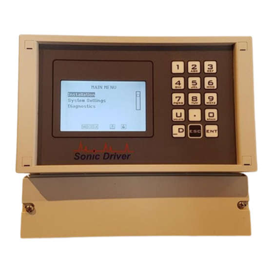
- Page 5 1.0 Introduction Congratulations on choosing the Sonic Driver Fixed-UFM wall mounted clamp-on ultrasonic flowmeter, figure(1). Figure(1) The Sonic Driver Fixed-UFM. The ultrasonic flowmeter (UFM) uses advanced Digital Signal Processing (DSP) and transit time measurement techniques (Sonic Driver ) to make accurate and reliable clamp-on ultrasonic flow velocity measurements.
-
Page 6: General Precautions
1.1 General Precautions The content of this manual has been carefully checked and is believed to be accurate. Sonic Driver Ltd assumes no responsibility for any inaccuracies that may be contained in this manual. In no event will Sonic Driver be liable for direct, indirect, special, incidental or consequential damages resulting from any defect or omission in this manual, even if we are advised of the possibility of such damages. -
Page 7: Keypad Functionality
2.0 Keypad Functionality The UFM keypad offers several dual operation FUNCTION KEYS for quick setup and display. Press any of the FUNCTION KEYS to go to the desired menu or display instantly. Note however that depending on what the user is attempting to do the focus of certain keys will change. When the user is navigating the UI and selecting a Menu screen;... - Page 8 Parameter entry When the user is editing a parameter and the parameter editing cursor starts to flash the keypad keys change function to become alphanumeric inputs; Enter "1". Enter "2". Enter "3". Enter "4". Enter "5". Enter "6". Delete a character or scroll up though available parameter options in a list. Enter "7".
- Page 9 3.0 FUNCTION KEY Functions The keypad has a number of FUNCTION KEYS, which allow the user to instantly access functions; <1> Quick Start This key jumps to the Main Menu with the Quick Start option highlighted. Press ENT to start the Quick Start sequence or navigate the UI in the usual way. <2>...
- Page 10 • Negative flow totaliser Net total is simply the sum of the positive and negative flow totals. <6> Flow Profile This key gives access to a display showing; • Reynolds Number • Flow profile correction K factor • Raw flow velocity •...
- Page 11 <.> Time Based Diagnostics This display shows diagnostics relating to the timing measurements being made by the UFM. • Delta Time • Transit Time • Path Time • dT Offset • SOS expected and measured The absolute upstream transit time through the fluid in the pipe and the absolute downstream transit time through the fluid in the pipe are usually of the order of hundreds of microseconds.
- Page 12 Signal strength indicates the detected strength of the sonic signal in decibels (dB). Signal strength is indicated by numbers from typically -25.0 to +55.0. Normally, the stronger the signal strength detected the better and more reliable the flow measurement is, as well as the more stable the measurement value obtained. Adjust the transducer positioning to the best position, within limits and check to ensure that enough sonic coupling compound is applied during installation in order to obtain the maximum signal strength.
- Page 13 4.0 Powering On To power on the UFM simply apply AC or DC power as appropriate to the model, see the installation manual for details of mounting and wiring the UFM and important safety information. As soon as the UFM is switched on a self-diagnostic program will start. If an error is detected an error message will be displayed prompting user action.
- Page 14 5.0 User Interface (UI) The Main Menu allows the user to select a group of parameters to edit or a meter function; • Quick Start • Installation • System Settings • Diagnostics • Input/Output • RS232/USB • Datalogger • Batching •...
- Page 15 Quick Start Function The Quick Start function takes the user through the minimum sequence of parameters needed to get the UFM measuring reliably and accurately; • Pipe Outer Diameter • Pipe Wall Thickness • Pipe Material • Liner Material • Fluid Type •...
- Page 16 Installation Menu The Installation Menu allows the user to edit parameters specific to the physical installation of the UFM on a pipe; • Pipe Settings • Liner Settings • Fluid Settings • Transducer Settings • Calibration Settings • Display Units •...
- Page 17 Pipe Menu This menu allows the user to change pipe settings. A test is made to check that the change has not resulted in a Closed Pipe. Pipe Outer Diameter The user is prompted to enter a value for the pipe outer diameter. The UFM comes in 3 different versions;...
- Page 18 This value is used in flow profile correction calculations. Pipe Sound Velocity Appearance of this parameter is context driven. If the Pipe Material is entered as Other then the user is prompted to enter a pipe transverse sound velocity. The user is prompted to enter the transverse speed of sound in the pipe. Allowed values are ranged 500 to 7000m/s, default 3206m/s (Carbon Steel).
- Page 19 Liner Menu This menu allows the user to change pipe lining settings. Liner Material The user can select a pipe liner material from a list; • None (Default) • Cement • Epoxy • Glass • PP • Teflon • Rubber •...
- Page 20 Fluid Menu This menu allows the user to change fluid settings. Fluid Type The user can select the fluid in the pipe from a list; • Water (Default) • Sea Water • Kerosene • Petrol • Fuel Oil • Crude Oil •...
- Page 21 Fluid Kinematic Viscosity Appearance of this parameter is context driven. If the user selected Other from the list of fluid types then the user is prompted to enter the kinematic viscosity of the fluid. Otherwise the kinematic viscosity of the fluid is read from a database held in the UFM. The user is prompted to enter the kinematic viscosity of the fluid.
- Page 22 • DN40 • Flow Other DM sensors are Sonic Driver standard PEEK/stainless steel design. DN sensors are Sonic Driver small pipe design. DS sensors are Sonic Driver large pipe design. If Flow Other is selected then the user will be prompted to enter detailed transducer specific information, see Appendix A.
- Page 23 • V is 2 passes, the most commonly used method, simplest to install as both sensors are on the same side of the pipe. • N is 3 passes, used on small diameter pipes. • W is 4 passes, used on the lowest diameter pipes. •...
- Page 24 Calibration Settings Menu This menu allows the user to change calibration and calculation settings. Low Flow Cutoff If the flow velocity falls below the low flow cutoff value, the measured flow velocity and calculated flow rate indication is driven to zero. This function can prevent the flow meter from reading flow after a pump is shut down but there is still circulating liquid creating movement in the pipe, which will result in a totaling error.
- Page 25 User Scaling Factor The manual PV scaling factor is used to modify the measurement results. The user can enter a numerical value other than “1.0” according to calibration results. The user is prompted to enter a measurement scaling value. Allowed values are ranged 0.001 to 1000.0, default 1.000.
- Page 26 Display Units Menu This menu allows the user to change display unit settings. Flow Rate Units The user can select the units to be used for display of flow rate from a list; • Cubic Meters (m3) • Litres (1) (Default) •...
- Page 27 Energy Units The user can select the units to be used for display of both energy flow rate and energy totaliser (net, positive and negative) from a list; • Giga Joule (GJ) (Default) • Mega Joule (MJ) • Kilo Joule (kJ) •...
- Page 28 Decimal Places The user can select how many Decimal Places (DP) flow velocity and flow rate measurement values are displayed to. Allowed values are ranged 0 to 3DP, the default is 2DP.
- Page 29 Totalisers Menu This menu allows the user to change totaliser settings. Net Flow Totaliser The user can turn a net flow totaliser On/Off so that net flow total is accumulated and displayed. By default the net flow totaliser is turned Off. Pos Flow Totaliser The user can turn a positive flow totaliser On/Off so that positive flow total is accumulated and displayed.
- Page 30 Factory Defaults The user is prompted to reload factory defaults and return the meter to its factory configuration. All parameters including Input/Output settings, RS232/USB, datalogger are reset to factory defaults. Display contrast is reset to the factory default. Tag and Identifier strings are reset to factory values. Key code is not defaulted.
- Page 31 System Settings Menu This menu amongst other things allows the user to edit parameters specific to the UFM internal real time clock; Date Set the RTC date. The UI checks for illegal entry and leap years. Time Set the RTC time, uses 24-hour format. Only enter hours and minutes. Date Format Select date format from a list;...
- Page 32 System Lock This option allows the user to decide whether to lock or unlock the UFM by selecting to turn the function On/Off. Once the system is locked, any modification to the system is prohibited, but the UI is navigable. Unlock the UFM by navigating to the System Lock menu and using the designated key code, see above.
- Page 33 The final datalogger memory test writes and reads back from all 16MB individually and can take up to 30 minutes. To stop this byte-to-byte test early press any key. Peripherals The user is taken through a factory series of tests which fully exercise the meter internal hardware; •...
- Page 34 System Info Menu This menu allows the user to view key meter values. Model Code Show model code of the meter. Serial No. Show the unique serial number assigned to the meter during manufacture. HW Issue Show the HW version for the meter and associated TOFM. SW Issue Show the SW version for the meter and associated TOFM.
- Page 35 Diagnostics Menu This menu allows the user to see a display of error reports, optional plug-in IO modules fitted, datalogger memory remaining (as a percentage and as an estimated time in hours) and other diagnostics. There are 3 screens of diagnostics in total, press ENT to move between them. The meter checks that the TOFM that is installed is functioning.
- Page 36 Input/Output As soon as the UFM is switched on a self-diagnostic program will start. As part of this diagnostic the UFM polls to determine which if any optional plug-in IO modules are fitted in its expansion slots If the range of fitted modules is found to have changed since last power on a message will be displayed prompting user action.
- Page 37 Relay Output Select Digital OP Mode Alarm Alarm Source Low Signal Fault System Velocity Rate Energy On point Off point Pulse Pulse Source Flow Net Tot Flow Pos Tot Flow Neg Tot Energy Net Tot Step Duration Batch Control Phase Detection Open Collector Output Select Digital OP Mode Alarm...
- Page 38 Flow Net Tot Flow Pos Tot Flow Neg Tot Energy Net Tot Step Duration Batch Control Phase Detection Current Output 4-20mA Iout Source Velocity Lower Value Upper Value Damping Error Hold 3.8mA/Off 21.0mA/On Hold Rate Lower Value Upper Value Damping Error Hold 3.8mA/Off...
- Page 39 Hold 3.8mA/Off 21.0mA/On Hold TOFM The TOFM module has no user programmable values. Current Input Iin Source Inlet Iin Units degC degF Outlet Iin Units degC degF Comp. Iin Units degC degF Inlet+Comp. Iin Units degC degF Outlet+Comp. Iin Units degC degF AI Batch...
- Page 40 Inlet Outlet Comp. Inlet+Comp. Outlet+Comp. PT100 Dynamic Dynamic Offset Fixed Value Modbus RTU Address Baud 9600 19200 Parity None Even Stop Bits Digital Input Select Digital Input Mode DI1 Batch DI2 Batch...
- Page 41 RS232/USB This menu allows the user to change serial communication settings for the RS232 and USB ports. Port The user can select which of the 2 available serial ports are used for communication from a list; • Off (Default) • USB •...
- Page 42 • Signal amplitude • Signal noise • Signal gain • Signal SNR • Dropped comms counter • Signal quality 1 • Signal quality 2 • Signal quality 3 • Control unit temperature • Inlet temperature • Outlet temperature • Fluid temperature •...
- Page 43 Datalogger This menu allows the user to edit parameters specific to the meters internal datalogger. The meter has a 16MB internal flash datalogger memory. As soon as the UFM is switched on a self-diagnostic program will start. As part of this diagnostic the UFM checks the function of the flash data memory hardware (4 individual chips, successful test indicated by a Pass for each) and reads any logged data to check its integrity (Progress shown by incrementing address).
- Page 44 Batching Function This menu allows the user to change settings relating to batch processing. Flow Batch Trigger The user can select how the batch process is triggered from a list; • Key Input (Default) • AI Up Edge • AI Down Edge •...
- Page 45 Otherwise press ENT to exit to the Main Menu.
- Page 46 Manual Totaliser Function This menu allows the user to manually start and stop a dedicated totaliser. Follow the instructions on the LCD. Simply press ENT to start and ESC to stop.
- Page 47 Phase Detection Function This menu allows the user to change settings relating to phase detection. The meter can identify different phases or fluids flowing in pipes by making speed of sound measurements in the fluid(s). The user starts the Phase Detection process by selecting this menu function and entering a value for the Phase Detection Target.
- Page 48 Heat Metering Heat meters measure the energy necessary to provide hot water or cooling to a location such as a building or room. The meter measures the energy on the supply or return side of a heating (boiler) or cooling (chiller) device by measuring the flow rate of heat or cooling fluid and the temperature difference between the supply and return legs of the system.
- Page 49 Specific Heat Capacity The UFM can make energy calculations using the Specific Heat Capacity (SHC) method, where the user must manually enter values for pipe inlet and outlet temperature. The user can enter a value for the Specific Heat capacity of the fluid flowing in the pipe. Allowed values are ranged 0.0 to 10.0J/(g.K), default 4185.6J/(g.K) (Water at 18degC).
-
Page 50: Appendix A Transducer Parameters
Appendix A Transducer parameters These parameters are only intended for trained service personnel. They are normally read from an external transducer memory chip which is supplied with a matched pair of transducers. Wedge Angle The user is prompted to enter a value for the transducer wedge angle. Allowed values are ranged 0.0 to 90.0deg, default 40.0deg. - Page 51 Zero Flow Offset The user can view/edit inherent offsets in the transducers. Allowed values are ranged -20.0 to +20.0ns, default 0.0ns. Zero Calibration and Zero Tracking adjust this value in real time when measuring when they are enabled. K factor Allows the entry of a factory calibrated meter factor.
-
Page 52: Appendix B Error Codes
• 5 Spare • 6 Spare • 7 Spare • 8 Spare • 9 Spare • 10 Spare • 11 Spare • 12 Spare • 13 Spare • 14 Spare • 15 Spare Spare bits are always 0. Sonic Driver...
Need help?
Do you have a question about the FIXED-UFM and is the answer not in the manual?
Questions and answers