
Related Manuals for Sonic Driver POCKET PLUS-UFM


Summary of Contents for Sonic Driver POCKET PLUS-UFM
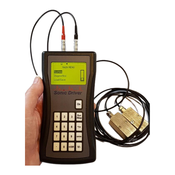
- Page 1 Made in Britain POCKET PLUS-UFM Ultrasonic Flowmeter Operating Instructions Version 3.0 13th March 2023 Copyright Sonic Driver Ltd 2023...
-
Page 2: Table Of Contents
Contents 1.0 Introduction 1.1 General Precautions 2.0 Keypad Functionality 3.0 FUNCTION KEY Functions <1> Quick Start <2> Transducer Positioning <3> ATA/ETA % <4> Flow Rate and Net Total <5> Flow Velocity, Rate and Totals <6> Flow Profile <7> Energy Rate and Net Total <8>... - Page 3 Calibration Settings Menu Low Flow Cut Corrected Flow User Offset User Scaling Set Zero Zero Tracking Tup Method Calculation Method Display Units Menu Flow Rate Units Flow Rate Time Units Totaliser Units Energy Units Energy Time Units Measurement Units Damping Totalisers Menu Net Flow Total Pos Flow Total...
- Page 4 Serial Menu Mode Baud Parity Logger Menu Interval Date Time Download Erase Load/Save Setups Menu Save Option Load Option Delete Option Appendix A Transducer parameters...
-
Page 5: Introduction
With the addition of a wall thickness measuring probe the UFM can also function as a pipe wall thickness gauge (WTG). The POCKET PLUS-UFM includes a date and time stamped 4MB datalogger and USB serial communications functionality as standard. When connected to a computer USB port or USB charger the UFM is powered over the USB. This... -
Page 6: General Precautions
1.1 General Precautions The content of this manual has been carefully checked and is believed to be accurate. Sonic Driver Ltd assumes no responsibility for any inaccuracies that may be contained in this manual. In no event will Sonic Driver be liable for direct, indirect, special, incidental or consequential damages resulting from any defect or omission in this manual, even if we are advised of the possibility of such damages. -
Page 7: Keypad Functionality
2.0 Keypad Functionality The UFM keypad offers several dual operation FUNCTION KEYS for quick setup and display. Press any of the FUNCTION KEYS to go to the desired menu or display instantly. Note however that depending on what the user is attempting to do the focus of certain keys will change. This key turns the flowmeter on. - Page 8 When the user is editing a parameter and the parameter editing cursor starts to flash the keypad keys change function to become alphanumeric inputs; Enter "1". Enter "2". Enter "3". Run/Stop No action. Enter "4". Enter "5". Enter "6". Enter "+" symbol or scroll up though available parameter options in a list. Enter "7".
-
Page 9: Function Key Functions
3.0 FUNCTION KEY Functions The keypad has a number of FUNCTION KEYS, which allow the user to instantly access functions; <1> Quick Start This key jumps to the Main Menu with the Quick Start option highlighted. Press ENTER to start the Quick Start sequence or navigate the UI in the usual way. <2>... -
Page 10: 6> Flow Profile
• Negative flow totaliser Net total is simply the sum of the positive and negative flow totals. <6> Flow Profile This key gives access to a display showing; • Reynolds Number • Flow profile correction K factor • Raw flow velocity •... -
Page 11: Time Based Diagnostics
<.> Time Based Diagnostics This display shows diagnostics relating to the timing measurements being made by the UFM. • Delta Time • Transit Time • Path Time • dT Offset • SOS The absolute upstream transit time through the fluid in the pipe and the absolute downstream transit time through the fluid in the pipe are usually of the order of hundreds of microseconds. - Page 12 indicated by numbers from typically -25.0 to +55.0. Normally, the stronger the signal strength detected the better and more reliable the flow measurement is, as well as the more stable the measurement value obtained. Adjust the transducer positioning to the best position, within limits and check to ensure that enough sonic coupling compound is applied during installation in order to obtain the maximum signal strength.
-
Page 13: Powering On
4.0 Powering On To power on a POCKET-UFM press and hold the On key. As soon as the UFM is switched on a self diagnostic program will start. If an error is detected an error message will be displayed prompting user action. If the error persists contact customer support. -
Page 14: User Interface (Ui)
5.0 User Interface (UI) The Main Menu allows the user to select a group of parameters to edit or a meter function; • Quick Start • Installation • System • Diagnostics • Serial • Logger • Load/Save... -
Page 15: Quick Start Function
Quick Start Function The Quick Start function takes the user through the minimum sequence of parameters needed to get the UFM measuring reliably and accurately; • Transducer Type • Transducer Mounting • Pipe Diameter • Pipe Wall Thickness • Pipe Material •... -
Page 16: Installation Menu
Installation Menu The Installation Menu allows the user to edit parameters specific to the physical installation of the UFM on a pipe; • Pipe • Liner • Fluid • Transducer • Calibration • Display Units • Totaliser • Load Defaults These parameters represent an extended set of parameters needed to get the UFM measuring and displaying values, above and beyond the very basic parameter set used by the Quick Start sequence. -
Page 17: Pipe Menu
Pipe Menu This menu allows the user to change pipe settings. A test is made to check that the parameters that are entered do not result in a Closed Pipe. Outer Diameter The user is prompted to enter a value for the pipe outer diameter. Allowed values are ranged 10.0 to 6500.0mm, default 60.6mm. -
Page 18: Wtg Sos
is prompted to enter a pipe transverse sound velocity. The user is prompted to enter the transverse speed of sound in the pipe. Allowed values are ranged 500 to 7000m/s, default 3206m/s (Carbon Steel default). WTG SOS This value is used to make wall thickness measurements using the UFM when fitted with a wall thickness probe rather than flow transducers, see the Transducer Type parameter below. -
Page 19: Liner Menu
Liner Menu This menu allows the user to change pipe lining settings. Material The user can select a pipe liner material from a list; • None (Default) • Cement • Epoxy • Glass • PP • Teflon • Rubber • Other The list allows no liner (None) to be selected. -
Page 20: Fluid Menu
Fluid Menu This menu allows the user to change fluid settings. Type The user can select the fluid in the pipe from a list; • Water (Default) • Sea Water • Kerosene • Petrol • Fuel Oil • Crude Oil •... -
Page 21: Density
viscosity of the fluid is read from a database held in the UFM. The user is prompted to enter the kinematic viscosity of the fluid. Allowed values are ranged 0.001 to 40000cST, default 1.08cST (Water at 18degC). Density Appearance of this parameter is context driven. If the user selected Other from the list of fluid types then the user is prompted to enter the density of the fluid. -
Page 22: Transducer Menu
• Flow Other • WTG DM sensors are Sonic Driver standard PEEK/stainless steel design. DN sensors are Sonic Driver small pipe design. DS sensors are Sonic Driver large pipe design. If Flow Other is selected then the user will be prompted to enter detailed transducer specific information, see Appendix A. -
Page 23: Wtg Standoff
• Z is 1 pass, most common on large diameter pipes. • V is 2 passes, the most commonly used method, simplest to install as both sensors are on the same side of the pipe. • N is 3 passes, used on small diameter pipes. •... - Page 24 Calibration Settings Menu This menu allows the user to change calibration and calculation settings. Low Flow Cut If the flow velocity falls below the low flow cutoff value, the measured flow velocity and calculated flow rate indication is driven to zero. This function can prevent the flow meter from reading flow after a pump is shut down but there is still circulating liquid creating movement in the pipe, which will result in a totaling error.
- Page 25 meter proceeds to measurement mode by using the transducer positioning FUNCTION KEY <2>. The user is prompted to couple and space the transducers in the normal way, but after this an additional optional automatic zero calibration is made. By default Set Zero calibration is turned Off. If Set Zero calibration is turned On then a zero flow calibration is made.
- Page 26 Display Units Menu This menu allows the user to change display unit settings. Flow Rate Units The user can select the units to be used for display of flow rate from a list; • Cubic Meters (m3) • Litres (1) (Default) •...
- Page 27 Energy Units The user can select the units to be used for display of both energy flow rate and energy totaliser (net, positive and negative) from a list; • Giga Joule (GJ) (Default) • Mega Joule (MJ) • Kilo Joule (kJ) •...
- Page 28 Totalisers Menu This menu allows the user to change totaliser settings. Net Flow Total The user can turn a net flow totaliser On/Off so that net flow total is accumulated and displayed. By default the net flow totaliser is turned Off. Pos Flow Total The user can turn a positive flow totaliser On/Off so that positive flow total is accumulated and displayed.
- Page 29 All Totalisers are reset to zero. Saved Setups are not affected. By default the factory reset is not active.
- Page 30 System Settings Menu LCD Backlight The user is prompted to turn the UFM LCD backlight on/off. By default the backlight is On. Audio The user is prompted to turn the UFM keypad audio on/off. By default the buzzer is On. The user can enter a site Tag for the meter, this is an 8 character alpha numeric.
- Page 31 TOFM Values This option allows the user to test the function of the UFM time of flight module using a calibrated test block. Serial This option allows the user to test the function of the UFM serial communication by streaming a test message.
- Page 32 System Info Menu This menu allows the user to view key meter values. Model Code Show model code of the meter. Serial No. Show the unique serial number assigned to the meter during manufacture. HW Issue Show the HW version for the meter. SW Issue Show the SW version for the meter.
- Page 33 Diagnostics Menu This menu allows the user to see a display of error reports. Each item is given a simple Pass/Fail indication. Error codes and their meanings can be found in the Main Menu under the Diagnostics Menu; • ADDR, there is a memory addressing problem. •...
- Page 34 Serial Menu This menu allows the user to change serial communication settings for the USB port. The USB serial communication connector is next to the flow transducer LEMO connectors at the top of the UFM. Mode The user is prompted to select the mode for the USB from a list; •...
- Page 35 • Signal quality 3 • Inlet temperature • Outlet temperature • Fluid temperature • Error code 1 • Error code 2 Baud The user is prompted to select the communication baud rate from a list; • 9600 • 19200 • 115200 (Default) Parity The user is prompted to select the communication parity from a list;...
- Page 36 Logger Menu This menu allows the user to edit parameters specific to the meters internal datalogger. The meter has a date and time stamped 4MB internal flash datalogger memory. As soon as the UFM is switched on a self-diagnostic program will start. As part of this diagnostic the UFM checks the function of the flash data memory hardware, successful test indicated by a Pass for each) and reads any logged data to check its integrity (Progress shown by incrementing address).
- Page 37 Load/Save Setups Menu This menu allows the user to Save, Load and Delete up to 10 meter configurations for different applications. Save Option Select Save from the list and press ENTER. A list of 10 available configuration spaces is displayed by name. Empty spaces are shown as - BLANK-.
- Page 38 Appendix A Transducer parameters These parameters are only intended for trained service personnel. Wedge Angle The user is prompted to enter a value for the transducer wedge angle. Allowed values are ranged 0.0 to 90.0deg, default 40.0deg. Wedge SOS 20 The user is prompted to enter a value for the speed of sound in the wedge at 20 degC.
- Page 39 Allowed values are ranged -20.0 to +20.0ns, default 0.0ns. Zero Calibration and Zero Tracking adjust this value in real time when measuring when they are enabled. K factor Allows the entry of a factory calibrated meter factor. Sonic Driver Ltd...
Need help?
Do you have a question about the POCKET PLUS-UFM and is the answer not in the manual?
Questions and answers