
Related Manuals for Sonic Driver FIXED-UFM


Summary of Contents for Sonic Driver FIXED-UFM
- Page 1 Made in Britain FIXED-UFM Ultrasonic Flowmeter Installation Manual Version 4.0 13th March 2023 Copyright Sonic Driver Ltd 2023...
-
Page 2: Table Of Contents
Contents 1.0 Introduction • 1.1 Transit Time Measurement • 1.2 Packing List • 1.3 General Precautions • 1.4 Cleaning • 1.5 Connecting the Flow Transducers • 1.6 Mounting the Flow Transducers • 1.7 Mounting the UFM • 1.8 Wiring the UFM •... - Page 3 Appendix A Contact Details Appendix B Table of fluid properties Appendix C Table of pipe and lining material properties Appendix D Table of speed of sound in water Appendix E Table of typical pipe roughness values...
-
Page 4: Introduction
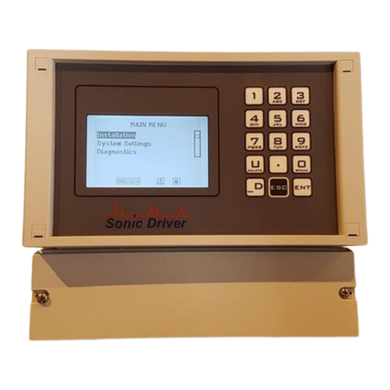
1.0 Introduction Congratulations on choosing the Sonic Driver FIXED-UFM clamp-on ultrasonic flowmeter, figure(1). Figure(1) The Sonic Driver FIXED-UFM. The ultrasonic flowmeter (UFM) uses advanced Digital Signal Processing (DSP) and transit time measurement techniques (Sonic Driver ) to make accurate and reliable clamp-on ultrasonic flow... -
Page 5: Transit Time Measurement
1.1 Transit Time Measurement The principle of flow measurement using ultrasonic clamp-on transit time measurement is simple, see figure(2). Figure(2) The principle of transit time flow measurement. Two ultrasonic transducers are coupled or clamped to the outside of the pipe at a predetermined distance apart. -
Page 6: Packing List
1.3 General Precautions The content of this manual has been carefully checked and is believed to be accurate. Sonic Driver Ltd assumes no responsibility for any inaccuracies that may be contained in this manual. In no event will Sonic Driver be liable for direct, indirect, special, incidental or consequential damages resulting from any defect or omission in this manual, even if we are advised of the possibility of such damages. -
Page 7: Connecting The Flow Transducers
1.5 Connecting the Flow Transducers Connect the flow transducers to the screw terminal connectors in the screw terminal compartment of the UFM, see figure(3). Figure(3) Flow transducer connection. The left-hand screw terminals connect the flow transducer which is mounted on the pipe downstream, the right-hand screw terminals connect the flow transducer which is mounted upstream. - Page 8 Figure(4) Flow transducer mounting, spacing is 25mm between front faces. In figure(5) and figure(6) the transducers are misaligned and twisted, as a result the UFM will make poor flow measurements. Figure(5) Misaligned transducers. Figure(6) Twisted transducers.
-
Page 9: Mounting The Ufm
1.7 Mounting the UFM When wall mounting the UFM refer to Figure(7), Figure(7) Wall mounting the UFM. 1.8 Wiring the UFM To power on the UFM simply apply AC or DC power as appropriate to the model. Always disconnect the mains supply before removing any covers and connecting any external wiring to the UFM. -
Page 10: Turning The Ufm On
With fixed wiring, a disconnecting device (local interruption) must be integrated into the power supply line. The disconnecting device must meet BS7671:2008 standards and regulations. It must be installed near the device, be able to be reached easily by the operator and labelled as a disconnecting device. -
Page 11: Using The Quick Start Sequence
2.0 Using the Quick Start Sequence Once powered on the UFM will be in UI mode displaying the Main Menu. The Main Menu allows the user to select a group of parameters to edit or a meter function; • Quick Start •... -
Page 12: Transducer Menu
• DN40 • Flow Other DM sensors are Sonic Driver standard PEEK/stainless steel design. DN sensors are Sonic Driver small pipe design. DS sensors are Sonic Driver large pipe design. If Flow Other is selected, then the user will be prompted to enter detailed transducer specific information. - Page 13 Ideally choose a number of passes that results in a path length in the fluid of 100mm or greater. • Z or 1 pass, most common on large diameter pipes, typically 100mm or more in diameter. If the UFM suggests a negative spacing, then this is measured as in figure(8). Figure(8) Z or 1 pass, demonstrating a negative transducer spacing.
- Page 14 Figure(10) W or 4 passes. • 5 to 13 and 14, etc. It may be that on the smallest diameter pipes then the recommended transducer spacing at 14 passes is not sufficient to allow the transducers to be coupled on the same side of the pipe, using an even number of passes as they still touch.
-
Page 15: Pipe Menu
2.2 Pipe Menu The following parameters allow the user to specify the pipe. 2.2.1 Outer Diameter The user is prompted to enter a value for the pipe outer diameter. The UFM comes in 3 different versions; • Standard - Allowed values are ranged 10.0 to 115.0mm •... -
Page 16: Liner Menu
2.3 Liner Menu This menu allows the user to change pipe lining settings. 2.3.1 Material The user can select a pipe liner material from a list; • None (Default) • Cement • Epoxy • Glass • PP • Teflon • Rubber •... -
Page 17: Fluid Menu
2.4 Fluid Menu This menu allows the user to change fluid settings. 2.4.1 Type The user can select the fluid in the pipe from a list; • Water (Default) • Sea Water • Kerosene • Petrol • Fuel Oil • Crude Oil •... -
Page 18: Sensor Positioning
3.0 Sensor Positioning After completing entry of all parameters in the Quick Start function sequence the user is prompted to confirm Transducer Type and is then taken to the Sensor Positioning screen. Using the entered parameters the UFM calculates and gives the required transducer spacing on the pipe. -
Page 19: Optimising Transducer Mounting Location
Figure(13) Non-ideal Sensor Positioning, transducers too close together. In figure(12) the received signal is too far to the right, the user should slide the transducers closer together. In figure(13) the received signal is too far to the left, the user should slide the transducers further apart. -
Page 20: Upstream And Downstream Pipe Runs
• Ideally the fluid should be free of particulates and bubbles, in the limit then an alternative method such as Doppler flow measurement may be required. • Pipe linings that are not bonded properly or are not conductive of ultrasound (rubber) will cause measurement problems. -
Page 21: Transducer Spacing
clamps or 10mm wide jubilee clips. 3.4 Transducer Spacing Given that all information regarding the installation has been entered accurately and the advice above has been followed then the UFM will measure reliably and accurately. This is confirmed by, • A strong received signal strength •... -
Page 22: Heat Metering
4.0 Heat Metering Heat meters measure the energy necessary to provide hot water or cooling to a location such as a building or room. The meter measures the energy on the supply or return side of a heating (boiler) or cooling (chiller) device by measuring the flow rate of heat or cooling fluid and the temperature difference between the supply and return legs of the system. - Page 23 Specific Heat Capacity The UFM can make energy calculations using the Specific Heat Capacity (SHC) method, where the user must manually enter values for pipe inlet and outlet temperature. The user can enter a value for the Specific Heat capacity of the fluid flowing in the pipe. Allowed values are ranged 0.0 to 10.0J/(g.K), default 4185.6J/(g.K) (Water at 18degC).
-
Page 24: Error Codes
5.0 Error Codes As soon as the UFM is switched on a self-diagnostic program will start. This program fully tests both the UFM hardware and software. If an error is detected an error message will be displayed prompting user action. If the error persists contact customer support, see appendix A. -
Page 25: Specification
In addition to showing icons, depending on the flow regime, see figure(15) the UFM displays; • Zero, no flow • Lam, laminar • Trans, transition • Turb, turbulent in the top-left of the display when in measurement mode. Laminar flow is generally regarded to exist for Reynolds Number less than 2300, transition is in the range 2300 to 4000 and turbulent flow typically has a Reynolds Number greater than 4000. - Page 26 Features • Intuitive installation using menu driven UI. • Full set of instrument and measurement diagnostics. • Signal oscilloscope for sensor positioning and diagnostics. • Internal database of pipe, fluid and lining materials. • Fluid database of sound speed, density, viscosity and SHC compensated for fluid temperature (if temperature is known from optional PT100 or 0/4 to 20mA temperature transmitter input) •...
-
Page 27: Product Identification
In the case of the UFM this is also written into the software and can be read using the UI. In the event of a need to contact Sonic Driver please have these codes available to quote. 9.0 Service The UFM is a sophisticated measuring instrument and contains no user serviceable parts. -
Page 28: Limited Warranty And Disclaimer
10.0 Limited Warranty and Disclaimer Sonic Driver Ltd warrants to the end purchaser, for a period of one year from the date of shipment from our factory, that all new products manufactured by it are free from defects in materials and workmanship. - Page 29 Appendix A Contact Details Telephone: +44(0)7971 273000 Postal Address: Sonic Driver Ltd, Lochiel, Llaneilian Road, Amlwch, Gwynedd, LL68 9HU, UK. Email: service@sonic-driver.com Website: www.sonic-driver.com Appendix B Table of fluid properties Fluid Longitudinal Speed of Sound (m/s) Water 20 (degC) 1482...
- Page 30 Galvanized Iron 0.15 Asphalted Cast Iron 0.12 Commercial or Welded Steel 0.045 PVC, Glass and other drawn tubing 0.0015 By default the Sonic Driver flowmeter uses a figure of 0.01mm as a good compromise for most common pipes. Sonic Driver...
Need help?
Do you have a question about the FIXED-UFM and is the answer not in the manual?
Questions and answers