Table of Contents
Advertisement
Quick Links
Advertisement
Table of Contents
Troubleshooting

Related Manuals for smith&nephew DYONICS RF System


Summary of Contents for smith&nephew DYONICS RF System
- Page 1 User’s Manual DYONICS™ RF System...
- Page 3 Glossary of Symbols See Instructions for Use Equipotential Ground Caution, Consult accompanying documents / Caution Tone Volume Control Fragile, Handle with Care Manufacturer Authorized representative in the European Community Temperature Limitations Date of Manufacture Keep Dry Coagulation Do not dispose in waste container Ablation Humidity Range: 10% - 85% R.H., Non-condensing CE mark and Identification number of Notified Body.
-
Page 4: Table Of Contents
Preface / Table of Contents Preface This equipment has been tested and found to comply with the limits for medical devices to IEC/EN 60601-1-2:2001. These limits are designed to provide reasonable protection against harmful interference in a typical medical installation. This equipment generates, uses, and can radiate radiofrequency energy and, if not installed and used in accordance with the instructions, may cause harmful interference to other devices in the vicinity. -
Page 5: Description
All Joints • Triangular Fibrocartilage (TFCC) Wrist Indications for Use • Villusectomy Knee The Smith & Nephew DYONICS RF System is Coagulation indicated for resection, ablation, and coagulation • ACL/PCL Knee of soft tissue and hemostasis of blood vessels in • Articular Cartilage... -
Page 6: Principle Of Operation
• Electrosurgical accessories, which are energy delivery with minimal collateral tissue damage. activated or hot from use, can cause a fire . The DYONICS RF System passes RF energy through • Accessory tips may remain hot enough to a conductive solution. The conductive solution cause burns after the electrosurgical current forms a thin layer between the active and return is deactivated . -
Page 7: Precautions
Precautions Precautions • To avoid risk of shock, do not allow patient contact with grounded conductive objects, such U.S. Federal law restricts this device to sale as a surgical table frame or an instrument table. by or on the order of a physician. Grounding pads should not be used. • Prior to initial use, ensure that all package inserts, • Do not contact metal objects with an activated warnings, precautions, and Instructions for Use... -
Page 8: Adverse Reactions
• Do not use other Smith & Nephew foot pedals. Note: Use only the foot pedal authorized by Smith Use only the foot pedal provided with the & Nephew for use with the DYONICS RF System. DYONICS RF System 5. Attach the DYONICS RF Probe to the cable • When endoscopes are used with necessary... -
Page 9: System Overview
System Overview System Overview 1. Generator 9. DYONICS™ RF Probe with Integrated Cable 2. Power cord 10. Shaft (DYONICS RF Probe) 3. Foot pedal 11. Return electrode (DYONICS RF Probe) 4. Ablation pedal 12. Active electrode tip (DYONICS RF Probe) 5. -
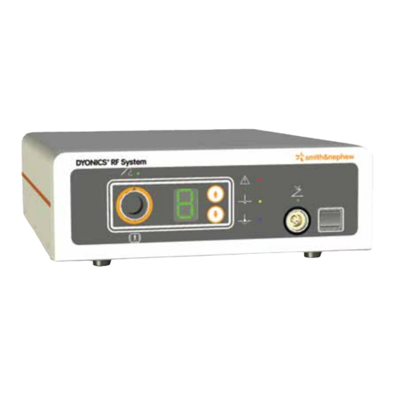
Page 10: Front Panel Layout
Front Panel Layout Front Panel Layout Figure 1. Generator front panel Cable Receptacle Warning Indicator Accepts Smith & Nephew DYONICS™ RF Probes Illuminates and alarms when a generator-specific with orange mating ends. failure or malfunction occurs. RF Probe Connected Indicator Ablation Activation Indicator Illuminates when the DYONICS RF Probe is Illuminates when the foot pedal Ablation function... -
Page 11: Rear Panel Layout
Rear Panel Layout Rear Panel Layout Figure 2. Generator rear panel Power Cord Receptacle / Fuse Holder TÜV Nord Classified Mark Accepts the generator power cord. The fuse holder Indicates compliance with applicable international is behind the receptacle. IEC 60601 series safety standards. Serial Communication Port Attention Symbol Allows the DYONICS™... -
Page 12: Instructions For Use
RF Probe for hemostasis of blood vessels. 1. Prior to each use, inspect the Smith & Nephew Setting Adjustment DYONICS RF System for possible damage to the The Setting Adjustment function adjusts the generator casing, accessories, and cables. voltage level on the generator. Each press of 2. -
Page 13: Rf Probe Selection
RF Probe Selection Select the DYONICS™ RF Probe most appropriate for Maintenance the procedure. The DYONICS RF System generator defaults to a recommended power setting for each Other than fuse replacement, the generator has DYONICS RF Probe as a guide for safe and effective no user-serviceable parts. -
Page 14: Troubleshooting Guide
A dual tone alarm sounds This is a safety feature of the Smith & Nephew DYONICS RF System and may occur and a red warning light if the DYONICS RF Probe is activated for an extended time without contacting tissue. -
Page 15: Error And Fault Messages
Maintenance and Troubleshooting / Product Specifications (continued) Error and Fault Messages When the system encounters an error, the generator first displays “E” and then the digit identifying the error. When the system encounters a fault, the generator first displays “F” and then the digit identifying the fault. Type Description LED Message... -
Page 16: Generator Output Graphs
Generator Output Graphs Generator Output Graphs The graph below shows the output power at each specified setting of the instrument. The used load was 250 Ohms for all settings (per IEC/EN 60601-2-2, subclause 6.8.3). Set Point Output Power vs . Setting at 250 Ohms Resistive Load DYONICS™... - Page 17 Generator Output Graphs (continued) The graph below shows the output power (at full and half settings) versus load resistance (per IEC/EN 60601-2-2, subclause 6.8.3). Half Power Full Power 1000 1200 Load Resistance (Ohms) Output Power vs . Load Resistance DYONICS™ RF System User’s Manual 10600463 Rev.
- Page 18 Generator Output Graphs (continued) The following graph illustrates the relationship between instrument settings and output RMS voltage. Set Point Output Voltage vs . Setting DYONICS™ RF System User’s Manual 10600463 Rev. D...
-
Page 19: Generator Classification And Safety Verification
Generator Classification and Safety Verification / Parts List Generator Classification and Parts List Safety Verification Part Number Description 72202149 DYONICS RF System Classification 72202491 DYONICS RF Power Cable, US According to IEC/EN 60601-2-2, Specification for 72202492 DYONICS RF Power Cable, High Frequency Surgical Equipment, the generator... -
Page 20: Warranty
**Service Replacement Program may not be offered in all countries. The Smith & Nephew DYONICS RF System is covered by the following U.S. Patents: 5,697,909; 5,697,281; 5,697,536; 5,697,882; 5,683,366; 5,681,282; 5,766,153; 5,810,764; 5,843,019; 5,871,469. Additional patents issued and pending. ™Trademarks of Smith & Nephew. Certain marks registered U.S. Patent & Trademark Office.
Need help?
Do you have a question about the DYONICS RF System and is the answer not in the manual?
Questions and answers