
Related Manuals for smith&nephew RT-PLUS


Summary of Contents for smith&nephew RT-PLUS
- Page 1 *smith&nephew Titel Surgical Technique “Intramedullary Application” RT-PLUS™ Text Modular Rotating Hinged...
-
Page 3: Table Of Contents
RT-PLUS™ Modular Table of Contents Introduction ................3 Concept/Description ............. 4 Indications ................8 Contraindications ..............8 Case Study ................9 Preoperative Planning ............10 Surgical Technique ............... 13 Postoperative Treatment ............51 References ................52 Sterilization ................. 53 Implants ................54 Instrumentation .............. -
Page 5: Introduction
It is a constrained rotating knee, the development of which drew upon knowledge and experience gained from state-of- the-art knee joint prosthesis. The RT-PLUS Modular knee system is the modular version of RT-PLUS and it represents a valuable addition to bicondylar surface replacement. -
Page 6: Concept/Description
RT-PLUS Modular to suit requirements. The implants are available in fi ve sizes (corresponding to RT-PLUS sizes 2, 4, 6, 8 and 10). Apart from size 2, the sizes can be combined with the next size up or down. - Page 7 Product Description Femoral component The femoral component is manufactured from CoCrMo alloy and is asymmetrical. The patellar groove is deeply hollowed out and presents an anatomical oblique outline. This feature offers improved patellar tracking and leverage on the knee extensor appara- tus.
- Page 8 The minimum effective PE thickness in the load zone is 8 mm. The selected manufacturing method, the design (condyles) and the high-quality material combine to form the proven wear- resistance of the insert. The tibial inserts are identical to those in the RT-PLUS™ portfolio. Tibial component The symmetrical tibial component is manu- factured from CoCrMo alloy.
- Page 9 Femoral and tibial blocks The femoral and tibial blocks are manufac- tured from CoCrMo alloy. In order to compensate different femoral and/ or tibial bone defects, there are distal femoral blocks available in heights of 5 mm, 10 mm and 15 mm, posterior femoral blocks in heights of 5 mm and 10 mm and proximal tibial blocks in heights of 5 mm, 10 mm and 15 mm.
-
Page 10: Indications
Trauma – induced femoral or tibial fractures • Due to the design, it is possible to switch with relatively little effort, even intraoperatively, • from the TC-PLUS™ knee system to the RT-PLUS™ Modular knee system, since the resections and prosthesis sizes are matching Contraindications Contraindications are: Acute or chronic, local or systemic infections (or in the case of a corresponding anamnesis) •... -
Page 11: Case Study
Case Study Preoperative situation Patient with severe joint instability (varus gonarthrosis) as well as medial joint destruction. Postoperative result Immediately postoperative; functional and pain-free reconstruction with RT-PLUS™ Modular knee. -
Page 12: Preoperative Planning
Preoperative Planning A full-leg X-ray with the patient in the standing position is recommended for preoperative- planning purposes. If this is not possible, an X-ray of the thigh, including the femoral head, should be taken. The X-ray images of the knee joint at three levels should be available for planning the surgery. - Page 13 Planning of Surgery Using the Radiograph The following procedure is recommended for the anterior-posterior whole leg imaging pro- cess: 1. The femoral axis A (anatomical axis) is drawn onto the radiograph. 2. A line is drawn from the femoral head to the center of the knee (mechanical axis D) on the radiograph.
-
Page 15: Surgical Technique
Surgical Technique Positioning of the patient for the surgery Surgery is performed whilst the patient is supine. It is recommended that the blood supply be partially blocked with the use of a tourniquet. But this is not absolutely necessary. The leg must be covered, so as to allow mo- vement, and secured to the operating table in such a way that the knee joint is brought into a stable 90°... - Page 16 Overview of the Resections Sequences for Primary Application It is important that the fl exion and extension gaps are identical. 1. Distal femoral resection and optional distal augment resection. 2. A/P femoral resections and optional posterior augment resection. 3. Chamfer resections and cutting out of the box.
- Page 17 Overview of the Resections Sequences for Revision Application The bone resections are refreshed after extraction of the primary implants. 1. Distal femoral resection and optional distal augment resection. 2. A/P femoral resections and optional posterior augment resection. 3. Chamfer resections and cutting out of the box.
- Page 19 Femoral Preparation Access: Please refer to the relevant surgical textbooks for the initial access to the knee. Note In addition to the bone resections, it is important to correct any ligament imbalance by appropriate soft-tissue procedures. If necessary, a general release should be performed on the side of the contracture prior to the bone resections.
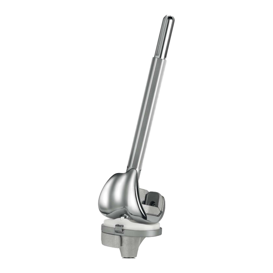
- Page 20 The Ø 8 mm IM rod is carefully inserted using the modular handle to approximately the isthmus of the femoral IM canal and removed again. It is important to work carefully to pre- vent excess pressure in the IM canal. The femoral IM canal is opened further with the Ø...
- Page 21 Controlling the stem position An extramedullary reamer alignment guide, which is attached to the reamer, can be used to check the position of the stem in axial alignment and depth (the end of the reamer alignment guide corresponds to the tip of the reamer).
- Page 22 Locating the distal femoral cutting block The 6° femoral bushing corresponds to the angle determined in the preoperative planning. The femoral bushing is inserted into the femoral suspension device, so that depending on which side is the operation, the mark L for left knee or R for right knee is visible on the arrow ▼.
- Page 23 Distal femoral resection The femoral/tibial revision cutting block is slid onto the bone. The distal femoral resection is then performed using a 1 mm saw blade through the 0 saw slot (closed slot with facet). Note For locking the femoral /tibial revision cutting block, an additional pin can be inserted into the oblique holes market with AUX.
- Page 24 Locating the A/P femoral cutting block The chosen trial stem is attached to the exten- sion for trial stem (Ø 8 mm) and inserted into the femoral IM canal. The A/P femoral cutting block revision is placed on top. Note When using distal femoral augmentation blocks, the corresponding blocks must be fixed on the A/P femoral cutting block revision.
- Page 25 A/P and chamfer resections The anterior femoral resection is made through the closed saw slot with the 1 mm saw blade (anterior slot with facet). The posterior femoral resection is made through the two open posterior saw slots (slots with facet). When using posterior femoral augmentation blocks, the resection is made through the open 5 mm and 10 mm saw slots.
- Page 26 Preparing the femoral box (IM) Note In order to improve support for the Hohman, we recommend preparing the femoral box after tibial preparation. Important This application is performed when bone tissue is not available to ensure good instrument support (especially in the anterior bone area and after explantation of a prosthesis).
- Page 27 Fix the box saw guide IM positioning device with pins with head (38 mm) through the dis- tal holes. Together with the trial stem and the trial stem extension, withdraw the box saw guide positioner using the trial stem handle, which is attached to the trial stem extension.
- Page 28 Excavate the femoral box with a thin, straight osteotome and a luer along the outer limits marked and prepared with the saw blade (with the osteotome, the two lateral box cuts are carefully posteriorely extended). From anterior into the IM canal hole, the narrow saw blade (or an osteotome) is intro- duced for cutting the posterior cortical box bone.
- Page 29 Check box position and box depth and fi na- lize with the box rasp (rasps for size 2 and for sizes 4–10). Important Introduce the box rasp only in the longitudinal direction; do not jam or tilt it because this can cause breakage of the femoral condyle.
- Page 30 Removing the dorsal condyle residue Important This must be checked in all cases! After having completed the femoral resections, use the curved osteotome to remove all osteophytes as well as protruding posterior condyles. At this point, a posterior contrac- ture can also be released. This will improve fl...
- Page 31 EM Femoral Box Preparation Option If bone tissue is distally and anteriorly available to ensure good instrument support, the “EM femoral box processing” version can be proceeded (this version is faster and easier in handling). EM preparation of the femoral box Note In order to improve support for the Hohman, we recommend preparing the femoral box after...
- Page 32 The resections are performed using a special 13 mm wide saw blade. The saw blade is inserted up to the RT 45 mark. Note Protect the vessels and nerves in the popliteal fossa. In the case of the guide for sizes 4–10, make the anterior box cut in the saw slot of the re- spective size.
- Page 33 Tibial Preparation The leg is fl exed and any remaining osteophytes and the intercondylar eminence are removed. Tibia opening Open the tibial IM canal with the Ø 8/14 mm stepped drill. Position the hole centrally M/L and one third from anterior. Preparing the tibial anchorage Reamers are used carefully and in progressive stages (starting with Ø...
- Page 34 Controlling the stem position An extramedullary reamer alignment guide, which is attached to the reamer, can be used to check the position of the stem in axial alignment and depth (the end of the reamer alignment guide corresponds to the tip of the reamer).
- Page 35 Locating the tibial cutting block The two tibial resection guide IM components are coupled together by jointing arrow arrow and pressing the button. The femoral/tibial revision cutting block is attached to the tibial resection guide IM with the top small grub screw and slid completely onto the trial stem extension (Ø...
- Page 36 Controlling the alignment and the tibial resection The alignment is checked again with the axial alignment rod. The rod tip must point to the center of the ankle joint. The tibial stylus can now be removed. The resection height is checked with the resection stylus.
- Page 37 Tibial resection The tibial resection is performed using a 1 mm saw blade through the 0 saw slot (closed slot with facet). Notes For locking the femoral /tibial revision cutting block, an additional pin can be inserted into the oblique holes marked with AUX. After resections the pin can be removed.
- Page 38 Controlling the joint gaps The tension in fl exion and extension is checked with spacers. The spacers (8, 11 and 14) re- present the femoral component and the full tibial component heights (tibial component and tibial insert). When using augmentation blocks, the corre- sponding spacer blocks must be fi...
- Page 39 Setting the tibial rotation The tibial rotation is determined anatomically statically (orientation to the tibial tuberosity, and the axial alignment rod tip must point to the center of the ankle joint). After preliminary drilling with the Ø 3.2 mm drill, the tibial sizer is fi xed with at least two bone pins with head.
- Page 40 Preparing the tibial IM canal Prepare the proximal tibial anchorage with the osteotome and the rasp. By using the thin narrow 10 mm chisel, the tibial cavity is pre- liminary prepared along the internal tibial chisel guide con- tour. This in oder to avoid bone fractures, especially with bad bone quality.
- Page 41 Trial reduction The purpose of the trial reduction is to check the radius of movement, patella guidance and the tension of the soft-tissue mechanism. The tibial trial together with the trial stem (depending on the last reamer diameter and depth) are inserted with using the impactor. Note It is possible that the same trial stem is re- quired on the femur and on the tibia.
- Page 42 When the defi nitive implants have been selected, make the components ready for assembly (see instructions on page 43 ff). Remove the trial components with the slap hammer, starting with the femur. Note As reference, it is recommended to leave as- sembled the trial components with stem and eventual blocks.
- Page 43 Patellar Preparation The leg is extended. Soft tissue on the posterior surface of the patella is exposed preserving the ligaments. If the posterior surface of the patella is not replaced, the patella is freed from osteo- phytes and denerved. Positioning the patella clamp and patella resection The patellar instruments permit the use of the “onlay”...
- Page 44 Milling Mount the patellar bushing onto the patellar clamp with the ratchet. Select the patellar reamer to match the corres- ponding patella size. Depending on the select- ed anchoraging technique, mill briefl y (“onlay” technique) or countersink by 3 mm to 5 mm (“inlay”...
- Page 45 Assembling the Implants – Components The assembling block is essential for safe and gentle assembling of the implants. Note When assembling the implant component, always start with the stem first. Then the blocks can be fixed. Otherwise the block screw may come loose during impacting. Important Be aware: if any screw or clamp is missing from the respective component or for any reason is not sterile, a set of replacement screws and clamps (page 57) is available.
- Page 46 Securing the stem With the stem screw the stem is additionally secured. The screw has to be tightened with the provided screwdriver. Note The stem screwdriver is intentionally slim designed and must be used carefully. Assembling the tibial blocks There are blocks with a thickness of 5 mm, 10 mm and 15 mm available for the tibial com- ponent (page 57).
- Page 47 Assembling the femoral component The femoral component (page 54) is posi- tioned in the specifi ed position on the assembling block. Fixing the stem (cementless) to the femo- ral component The stem (page 58) is inserted into the taper. It is recommended to turn the stem so that the security screw is positioned medially (lower stress in this zone, and in addition will facilitate the screwing later on), and that no...
- Page 48 Securing the stem With the stem screw the stem is additionally secured. The screw has to be tightened with the provided screwdriver. Note The stem screwdriver is intentionally slim designed and must be used carefully. Assembling the femoral blocks There are blocks with a thickness of 5 mm, 10 mm and 15 mm available for the femoral components (15 mm only distal) (page 56).
- Page 49 Modern cementing techniques using a vacuum mixer and jet lavage are recommended. The RT-PLUS™ Modular knee is used with cement, with the exception of cementless stems. First cement the tibial component and then the femoral component.
- Page 50 The femoral component is hammered using the impactor. Here, too, continuous pressure must be maintained and excess cement removed. Important Make sure that the posterior femoral condyles do not come into contact with the tibial com- ponent when impacting the femoral component. We recommend covering the tibial component with a compress.
- Page 51 Fixation of the tibial insert Place the impacting attachment on the plug inserter. In extension position the tibial insert clamp is manually completely inserted from anterior to posterior by using the plug inserter with the impacting attachment fi tted. It should end up positioned completely against the tibial insert and the tibial component.
- Page 52 Implanting the cemented patellar component If patellar replacement is indicated, the patel- lar component (page 54) of the TC-PLUS™ knee system is used since the geometry of the patellar groove is matched to this implant. Mount the patellar inserter on the patellar clamp with the ratchet.
-
Page 53: Postoperative Treatment
Postoperative Treatment Rehabilitation The operated leg is immobilized in a splint and the knee joint is cooled. Isometric con- traction exercises should be performed on the fi rst postoperative day. Thrombosis prophylaxis is required until full load can be borne. On the second postoperative day, after remov- ing the drains, assisted movement exercises and the use of a motorized splint (CPM) are... -
Page 54: References
A Method Proposed and Applied J Bone Joint Surg (Br) 67 (1985 Nov) 775–779 Malzer U, Schuler P 5 Years Results With The RT-PLUS™ Solution Constrained Total Knee (Poster) EFORT Congress, June 4–7, 2005, Lisbon, Portugal Müller C, Basad E, Melzer C Mid Term Result With A New Rorating Hinge Total Knee Arthroplasty (Poster) AAOS Annual Meeting, March 5–9, 2008, San Francisco, USA... -
Page 55: Sterilization
Sterilization Implants All the implants described in this Surgical Technique are sterile when they are delivered by the manufacturer. Resterilization is not allowed. Instruments System components and instruments are not sterile when they are delivered. Before use they must be cleaned by the usual methods in accordance with internal hospital regulations and sterilized in an autoclave in accordance with the legal regulations and guidelines appli- cable in the relevant country. -
Page 56: Implants
Implants RT-PLUS™ Modular Implants for Cemented Application Femoral components left Femoral components right Art. No. Art. No. Art. No. Art. No. PLUS S&N Size PLUS S&N Size 24322 75005554 24312 75005549 24324 75005555 24314 75005550 24326 75005556 24316 75005551 24328... - Page 57 75005487 14 mm 24076 75005488 8 mm 24077 75005489 11 mm 24078 75005490 14 mm 24086 75005491 8 mm 24087 75005492 11 mm 24088 75005493 14 mm The tibial inserts are the same as those of the RT-PLUS™ knee system.
- Page 58 Femoral blocks distal Art. No. Art. No. PLUS S&N Size Height 24371 75005574 5 mm 24372 75005575 10 mm 24373 75005576 15 mm 24374 75005577 5 mm 24375 75005578 10 mm 24376 75005579 15 mm 24377 75005580 5 mm 24378 75005581 10 mm 24379...
- Page 59 Tibial blocks Art. No. Art. No. PLUS S&N Size Height 24300 75005539 5 mm 24301 75005540 10 mm 24390 75005589 15 mm R-lal/L-med 24395 75005594 15 mm L-lat/R-med 24302 75005541 5 mm 24303 75005542 10 mm 24391 75005590 15 mm R-lal/L-med 24396 75005595 15 mm L-lat/R-med...
- Page 60 75005529 200 mm Ø 16 mm 24262 75005527 200 mm Ø 18 mm 24265 75005530 200 mm Ø 20 mm 24263 75005528 200 mm Cemented and cementless stems are identical for femoral and tibial components of RT-PLUS™ Modular knee system.
-
Page 62: Instrumentation
Instrumentation RT-PLUS™ Modular Instrument Set Set No. PLUS/S&N 0944033/75200235 Trial stems and reamers Case Set No. PLUS/S&N 0944034/75200236 Art. No. Art. No. PLUS S&N Description Size 240462 75005464 Case Trial Stems, Empty 990019 75007661 Case Lid Ø 10 / 95 mm... - Page 63 Optional cemented trial stems (on request) Set No. PLUS/S&N 0944045/75200247 Art. No. Art. No. PLUS S&N Description Size ¸ 240109 75005338 Trial Stem 95 mm 240398 75005422 Trial Stem 120 mm 240110 75005339 Trial Stem 160 mm ¸ OPTIONAL µ...
- Page 64 Femoral instruments Case Set No. PLUS/S&N 0944035/75200237 Art. No. Art. No. PLUS S&N Description Size 240463 75005465 Case Femoral Instruments, Empty 990019 75007661 Case Lid 240169 75005364 IM Femoral Drill Guide, Adjustable 240002 75005299 Ø 8 / 14 mm 240003 75005300 Stepped Drill Ø...
- Page 65 Optional drill with AO connection (on request) Set No. PLUS/S&N 0944046/75200248 Art. No. Art. No. PLUS S&N Description Size Ø 8 / 14 mm ( ) 240374 75005412 Stepped Drill (AO) Ø 8 mm ( ) 251097 75005673 IM Drill with Starter Tip (AO) Ø...
- Page 66 Femoral trials Case Set No. PLUS/S&N 0944036/75200238 Art. No. Art. No. PLUS S&N Description Size 240464 75005466 Case Femoral Trials, Empty 990019 75007661 Case Lid 240300 75005384 Femoral Trial Left 240301 75005385 Femoral Trial Left 240302 75005386 Femoral Trial Left 240303 75005387 Femoral Trial Left...
- Page 68 Tibial instruments Case Set No. PLUS/S&N 0944037/75200239 Art. No. Art. No. PLUS S&N Description Size 240465 75005467 Case Tibial Instruments, Empty 990019 75007661 Case Lid 600162 75007131 Tibial Resection Guide IM (I / II) ± 6 mm 600173 75010947 Tibia Stylus 1 mm / 11 mm 240438 75000979...
- Page 69 µ...
- Page 70 Tibia trials Case Set No. PLUS/S&N 0944038/75200240 Art. No. Art. No. PLUS S&N Description Size 240466 75005468 Case Tibial Trials, Empty 990019 75007661 Case Lid 240411 75005430 Tibial Trial 240412 75005431 Tibial Trial 240413 75005432 Tibial Trial 240414 75005433 Tibial Trial 240415 75005434 Tibial Trial...
- Page 72 Assembly instruments Case Set No. PLUS/S&N 0944039/75200241 Art. No. Art. No. PLUS S&N Description Size 240467 75005469 Case Assembly Instrument, Empty 990019 75007661 Case Lid 600181 75007142 Slap Hammer 600300 75007202 Modular Handle (2 pieces) 600288 75007200 Impactor Small 600289 75007201 Impactor Large...
- Page 73 µ ¹ ¸ ¹...
- Page 74 Patellar instruments Case Set No. PLUS/S&N 0944003/75200207 Art. No. Art. No. PLUS S&N Description Size 22000451 75018088 Case Patellar Instruments, Empty 990019 75007661 Case Lid 251204 75005702 Patellar Clamp 252203 75005881 Patellar Clamp Cutting Guide Ø 26 / 10 mm 251292 75005723 Patellar Trial...
- Page 75 µ...
-
Page 76: Product Overview (Combination Tables)
Product Overview... - Page 78 Documents Note The following documents are available for your assistance. Product-accompanying Documents Description Lit. No. Product Portfolio PLUS SOLUTION KNEE FAMILY 1685 Sawblades for the PLUS SOLUTION KNEE FAMILY 1403 Surgical Technique “Intramedullary Application” 1313 Product Information 1330 X-Ray Templates (1.15:1) 1135-A-B X-Ray Templates (1:1) 1584-A-B...
- Page 80 Manufacturer Contact Smith & Nephew Orthopaedics AG For further information please contact Erlenstrasse 4a our local sales offi ce. 6343 Rotkreuz www.smith-nephew.com Switzerland ™Trademark of Smith & Nephew Lit. No. 1313-e Ed. 05/09 0 1 2 3...
Need help?
Do you have a question about the RT-PLUS and is the answer not in the manual?
Questions and answers