Table of Contents
Advertisement
Quick Links
Advertisement
Table of Contents

Related Manuals for Komfovent KOMBI Series


Summary of Contents for Komfovent KOMBI Series
- Page 1 KOMBI INSTALLATION MANUAL...
-
Page 3: Table Of Contents
6�3� Connection of Cables and Wires Between Sections ��������������������������������������������������������������������������������������������������38 6�4� Control Panel Installation ����������������������������������������������������������������������������������������������������������������������������������������������������39 7. COMMISSIONING AND INSPECTION OF THE UNIT ����������������������������������������������������������������������������������������������������41 7�1� Fast Check ���������������������������������������������������������������������������������������������������������������������������������������������������������������������������������43 8. TECHNICAL SPECIFICATIONS ������������������������������������������������������������������������������������������������������������������������������������������������44 KOMFOVENT UAB reserves the right to change information without prior notice KOMBI_installation manual_24-02... -
Page 4: Introduction
• Maximum pressure in cold water supply system – 6 atm. If water pressure in the sys- tem is higher, a pressure relief valve must be installed. KOMFOVENT UAB reserves the right to change information without prior notice KOMBI_installation manual_24-02... -
Page 5: 1�2� Structure
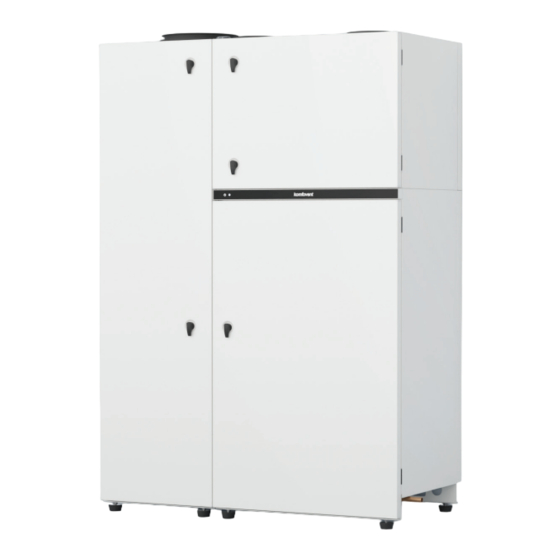
All systems can operate independently or in combination based on user’s settings� Fig. 1. KOMBI unit 1 – heat pump, 2 – ventilation unit, 3 – indication bar, 4 – domestic hot water tank KOMFOVENT UAB reserves the right to change information without prior notice KOMBI_installation manual_24-02... - Page 6 The inspection side determines how the air ducts and water pipes will be routed, therefore it must be considered when choosing the installation location� Depends on the order� KOMFOVENT UAB reserves the right to change information without prior notice KOMBI_installation manual_24-02...
-
Page 7: 1�2�1� Heat Pump
1 – heat pump fan, 2 – heat exchanger (evaporator), 3 – air filter, 4 – compressor’s frequency converter, 5 – heat exchanger (refrigerant - water), 6 – control automatics, 7 – compressor, 8 – refrigerant humidity indicator, 9 – automatic circuit breakers KOMFOVENT UAB reserves the right to change information without prior notice KOMBI_installation manual_24-02... -
Page 8: 1�2�2� Air Handling Unit
1 – fans, 2 – control automatics, 3 – rotary heat exchanger, 4 – water heater / cooler, 5 – air filters, 6 – automatic air release valve, 7 – condensate drainage connection KOMFOVENT UAB reserves the right to change information without prior notice KOMBI_installation manual_24-02... -
Page 9: 1�2�3� Hot Water Preparation System
5 – safety valves, 6 – electric heater, 7 – water valves with actuators, 8 – domestic hot water tank, 9 – water pressure manometer, 10 – coarse water filter, 11 – expansion vessel for hot water system KOMFOVENT UAB reserves the right to change information without prior notice KOMBI_installation manual_24-02... -
Page 10: Transportation And Storage
3 – Fastening screws at the bottom of the pallet (8 pcs�) UAB KOMFOVENT does not take any responsibility for any losses caused by the carrier during transportation and unloading� KOMFOVENT UAB reserves the right to change information without prior notice... - Page 11 AHU from the hot water section� For this purpose, you must remove the side panel of the hot water section, unscrew water pipes and condensate drainage, disconnect cables and remove four screws in the corners of the section� KOMFOVENT UAB reserves the right to change information without prior notice KOMBI_installation manual_24-02...
- Page 12 KOMFOVENT UAB reserves the right to change information without prior notice KOMBI_installation manual_24-02...
-
Page 13: Mechanical Installation
17 – cold water inlet, 18 – domestic hot water, 19 – hot water recirculation inlet (optional function), 20 – coarse water filter, 21 – expansion vessel for hot water system (8 l), ODA – outdoor air, SUP – supply air, ETA – extract air, EHA – exhaust air KOMFOVENT UAB reserves the right to change information without prior notice KOMBI_installation manual_24-02... -
Page 14: 3�1� Requirements For Mounting Location And Installation Base
The unit must be installed in a way to allow partial or full disassembling, if needed (e�g�, in case of heavy repairs)� KOMFOVENT UAB reserves the right to change information without prior notice KOMBI_installation manual_24-02... -
Page 15: 3�2� List Of Received Parts
Bolts for nuts for external fasteners (M6 x 20) – 2 pcs� Installation Manual – 1 pc� User Manual – 1 pc� Door handles – 6 pcs� KOMFOVENT UAB reserves the right to change information without prior notice KOMBI_installation manual_24-02... -
Page 16: 3�3� Recommended Accessories
Properly tighten the pipes to the heat exchanger (refriger- ant – water)� Place gaskets on the pipes to seal the cavities in the unit body� KOMFOVENT UAB reserves the right to change information without prior notice KOMBI_installation manual_24-02... - Page 17 Fasten both sections together using four bolts (from the water tank side)� M8x20 Tighten two external fasteners at the top� M6x20 KOMFOVENT UAB reserves the right to change information without prior notice KOMBI_installation manual_24-02...
- Page 18 Connect wire connectors that are marked with stickers (see section “Installation of Electrical Compo- nents”)� Make sure that connected wires are marked the same on both sides� Tighten connection pipes to the water tank pipeline� KOMFOVENT UAB reserves the right to change information without prior notice KOMBI_installation manual_24-02...
-
Page 19: Mechanical Installation: Air Ducts
Air ducts connecting the air handling unit to the exterior of the building must be in- sulated (insulation thickness 50–100 mm) to prevent condensation on cold surfaces. KOMFOVENT UAB reserves the right to change information without prior notice KOMBI_installation manual_24-02... -
Page 20: 4�1� Installation Of Ventilation Air Duct System
• In order to minimise the AHU generated noise and noise moving through the ducts into ventilated areas, sound suppressors must be connected to the AHU. KOMFOVENT UAB reserves the right to change information without prior notice KOMBI_installation manual_24-02... -
Page 21: 4�2� Installation Of The Heat Pump Air Ducts
What is more, these can be connected both to the heat pump’s and AHU’S air ducts going outside� Also, the length of the box is adjustable so it can fit walls of various thickness� Sold separately� KOMFOVENT UAB reserves the right to change information without prior notice KOMBI_installation manual_24-02... - Page 22 Just like in case of the AHU, external grilles of the heat pump should be installed on different sides of the building or as far away from each other as possible� Sold separately� KOMFOVENT UAB reserves the right to change information without prior notice KOMBI_installation manual_24-02...
-
Page 23: Mechanical Installation: Hydraulic System
KOMBI - A9 - ��� 1,54 m ≤ 0,34 m KOMBI – A7 - ��� 1,2 m ≤ 0,34 m KOMFOVENT UAB reserves the right to change information without prior notice KOMBI_installation manual_24-02... - Page 24 (No 4) and special inhibitors are recommended to protect the system from rust� The exact components to be used depend on the design of building’s heating system. KOMFOVENT UAB reserves the right to change information without prior notice KOMBI_installation manual_24-02...
- Page 25 , 3 – shut-off valves, 4 – magnetic filter, 5 – buffer tank, 6 – overflow valve, 7 – manifolds Recommended if the system volume is greater than 250 l� Recommended if the system volume is greater than 250 l� KOMFOVENT UAB reserves the right to change information without prior notice KOMBI_installation manual_24-02...
- Page 26 6 – hydraulic separation vessel, 7 – manifolds, 8 – Circulation pump Recommended if the system volume is greater than 250 l� Recommended if the system volume is greater than 250 l� KOMFOVENT UAB reserves the right to change information without prior notice KOMBI_installation manual_24-02...
-
Page 27: 5�2� Examples Of A Hot Water System
, 2 – one way valve, 3 – shut-off valves, 4 – mechanical cleaning filter, 5 – pressure regulating valve Recommended when the water inlet pressure is higher than 4 bar� KOMFOVENT UAB reserves the right to change information without prior notice KOMBI_installation manual_24-02... - Page 28 , 2 – one way valve, 3 – shut-off valves, 4 – mechanical cleaning filter, 5 – pressure regulating valve Hot water recirculation is an optional function� Recommended when the water inlet pressure is higher than 4 bar� KOMFOVENT UAB reserves the right to change information without prior notice KOMBI_installation manual_24-02...
-
Page 29: 5�3� Connecting Pipeline To The Unit
3 – heating system inlet (1/2“), 4 – domestic cold water inlet (1/2“), 5 – domestic hot water supplied to the system (1/2“), 6 – recirculated hot water (1/2“) Hot water recirculation is an optional function� KOMFOVENT UAB reserves the right to change information without prior notice KOMBI_installation manual_24-02... -
Page 30: 5�3�1� Filling Of The Hydraulic System
3 of them are near the water tank and one in the AHU� To open the valves, turn the black air release valve cap two full turns counter-clockwise� Fig. 22. Location of automatic air release valves KOMFOVENT UAB reserves the right to change information without prior notice KOMBI_installation manual_24-02... - Page 31 When filling hydraulic systems, check the KOMBI pipe connections to see if they have not loosened during transportation. In case of water leakage, stop filling up of the system and fasten the loose connections. KOMFOVENT UAB reserves the right to change information without prior notice KOMBI_installation manual_24-02...
-
Page 32: 5�4� Condensate Drainage
Condensate collection location must be easily accessible for cleaning and disinfection� Do not connect both drainage hoses together (for example, with a 3-way valve). KOMFOVENT UAB reserves the right to change information without prior notice KOMBI_installation manual_24-02... - Page 33 AHU and under the heat pump heat exchanger� In this way, you will fill the drainage siphons or hose loops with water and check whether the condensate drains properly from the unit� KOMFOVENT UAB reserves the right to change information without prior notice KOMBI_installation manual_24-02...
-
Page 34: Installation Of Electrical Components
All external electrical elements must be connected strictly according to the wiring diagram of the unit. • Do not disconnect the connectors by pulling wires or cables. KOMFOVENT UAB reserves the right to change information without prior notice KOMBI_installation manual_24-02... - Page 35 PE terminals as well as automatic switch in QF6 pump section� To access the connection points, remove the cover of the automation box� Fig. 27. Connecting the power supply cable KOMFOVENT UAB reserves the right to change information without prior notice KOMBI_installation manual_24-02...
-
Page 36: 6�2� Connection Of Electrical Components
Fig. 29. Main board of C9 control panel 1 – terminal sticker, 2 – terminals for external components, 3 –fan pressure sensors, 4 – LAN or Internet connection, 5 – control panel connection KOMFOVENT UAB reserves the right to change information without prior notice KOMBI_installation manual_24-02... - Page 37 B5 (14 – 15 ) – return water temperature sensor of the AHU heater / cooler is already connected here� FAULT SIGNAL (16, 19) – contacts 16 and 19 are closed if KOMBI unit has critical alarms or malfunctions� KOMFOVENT UAB reserves the right to change information without prior notice KOMBI_installation manual_24-02...
-
Page 38: 6�3� Connection Of Cables And Wires Between Sections
Cable connectors have labels with connector number; only connect connectors with the same number� Fig. 31. Cable connections between sections 1 – power supply cables, 2 – communication cables between electronic boards 3 – labels with connection numbers KOMFOVENT UAB reserves the right to change information without prior notice KOMBI_installation manual_24-02... -
Page 39: 6�4� Control Panel Installation
LIN A Yellow +24V +24V 4 x 0,22 mm 2 4 x 0,22 mm 2 < 150 m < 150 m Fig. 32. Control panel wiring diagram KOMFOVENT UAB reserves the right to change information without prior notice KOMBI_installation manual_24-02... - Page 40 Wrong screws may damage electronics board. • Do not use sharp tools for pinning contacts in the control panel (e.g., screwdriver). Please use a pencil or a ballpoint. KOMFOVENT UAB reserves the right to change information without prior notice KOMBI_installation manual_24-02...
-
Page 41: Commissioning And Inspection Of The Unit
Solid red – unit is turned off� • Solid white – unit is in operation; • Blinking red – unit is stopped or error messages are displayed� KOMFOVENT UAB reserves the right to change information without prior notice KOMBI_installation manual_24-02... - Page 42 4� Press a return icon at the top of the window to return to the main screen� Menu Menu Overview Overview OFF? Scheduling Planavimas Settings Settings For more information about control and settings see “KOMBI User Manual”� KOMFOVENT UAB reserves the right to change information without prior notice KOMBI_installation manual_24-02...
-
Page 43: 7�1� Fast Check
Check if there is no moisture in the refrigerant system Hydraulic systems are vented There are no unusual noise or vibrations during operation Other comments: Installer Company Tel� No� Date Signature KOMFOVENT UAB reserves the right to change information without prior notice KOMBI_installation manual_24-02... -
Page 44: Technical Specifications
Heat pump section dimensions B×H×L, mm 550 × 2010 × 684 Boiler and AHU section dimensions B×H×L, mm 850 × 2010 × 684 Maintenance space, mm ≥ 850 KOMFOVENT UAB reserves the right to change information without prior notice KOMBI_installation manual_24-02... - Page 45 , dB(A) Air filters dimensions B×H×L, mm 585 × 258 × 46 Air filters class according to ISO 16890, Supply/Extract ePM1 60 % / ePM10 50 % KOMFOVENT UAB reserves the right to change information without prior notice KOMBI_installation manual_24-02...
- Page 46 Water heating time from 10°C to 45°C, min� Tap profile according to DIN EN 16147 Number of water circulation pumps (optional) Max� water pump power consumption, W Tank disinfection water temperature max�, °C KOMFOVENT UAB reserves the right to change information without prior notice KOMBI_installation manual_24-02...
- Page 47 – A2/W45 2,80 3,21 – A7/W45 2,47 3,65 – A2/W55 3,17 2,84 – A7/W55 2,90 – A35/W18 1,38 – 5,07 A35/W7* 1,24 – 2,67 * AHU only KOMFOVENT UAB reserves the right to change information without prior notice KOMBI_installation manual_24-02...
- Page 48 SERVICE AND SUPPORT PARTNERS LITHUANIA J� PICHLER Gesellschaft m� b� H� www�pichlerluft�at UAB KOMFOVENT Phone: +370 5 200 8000 Ventilair group www�ventilairgroup�com service@komfovent�com ACB Airconditioning www�acbairco�be www�komfovent�com REKUVENT s�r�o� www�rekuvent�cz FINLAND Komfovent Oy WESCO AG www�wesco�ch Muuntotie 1 C1 FI-01 510 Vantaa, Finland SUDCLIMATAIR SA www�sudclimatair�ch...
Need help?
Do you have a question about the KOMBI Series and is the answer not in the manual?
Questions and answers