Makita CE003G Instruction Manual
Cordless power cutter
Hide thumbs
Also See for CE003G:
- Instruction manual (112 pages) ,
- Instruction manual (21 pages) ,
- Instruction manual (93 pages)
Table of Contents
Advertisement
Quick Links
Advertisement
Table of Contents

Subscribe to Our Youtube Channel
Related Manuals for Makita CE003G


Summary of Contents for Makita CE003G
- Page 1 INSTRUCTION MANUAL Cordless Power Cutter CE003G CE004G Read before use.
-
Page 2: Specifications
SPECIFICATIONS Model: CE003G CE004G Wheel diameter 230 mm 305 mm Max. wheel thickness 3.0 mm 5.0 mm Max.cutting depth 88 mm 121 mm Rated speed 6,600 min 5,000 min Rated voltage D.C. 36 V - 40 V max Max. permitted pressure of feed-water... -
Page 3: Safety Warnings
Model Sound pressure Sound power level Uncertainty (K) : level (L ) : (dB(A)) ) : (dB(A)) (dB(A)) CE003G CE004G NOTE: The declared noise emission value(s) has been measured in accordance with a standard test method and may be used for comparing one tool with another. NOTE: The declared noise emission value(s) may also be used in a preliminary assessment of exposure. WARNING: Wear ear protection. WARNING: The noise emission during actual use of the power tool can differ from the declared val- ue(s) depending on the ways in which the tool is used especially what kind of workpiece is processed. - Page 4 Do not abuse the cord. Never use the cord for carrying, pulling or unplugging the power tool. Keep cord away from heat, oil, sharp edges or moving parts. Damaged or entangled cords increase the risk of electric shock. When operating a power tool outdoors, use an extension cord suitable for outdoor use.
- Page 5 Battery tool use and care Always use undamaged wheel flanges that are of correct diameter for your selected wheel. Recharge only with the charger specified by Proper wheel flanges support the wheel thus the manufacturer. A charger that is suitable for reducing the possibility of wheel breakage. one type of battery pack may create a risk of fire when used with another battery pack. Do not use worn down reinforced wheels from larger power tools.
- Page 6 Kickback and related warnings 10. Use extra caution when making a “pocket cut” Kickback is a sudden reaction to a pinched or snagged into existing walls or other blind areas. The protruding wheel may cut gas or water pipes, elec- rotating wheel. Pinching or snagging causes rapid stalling of the rotating wheel which in turn causes the trical wiring or objects that can cause kickback.
- Page 7 (2) Avoid storing battery cartridge in a con- CAUTION: Only use genuine Makita batteries. tainer with other metal objects such as Use of non-genuine Makita batteries, or batteries that nails, coins, etc. have been altered, may result in the battery bursting (3) Do not expose battery cartridge to water causing fires, personal injury and damage. It will...
-
Page 8: Parts Description
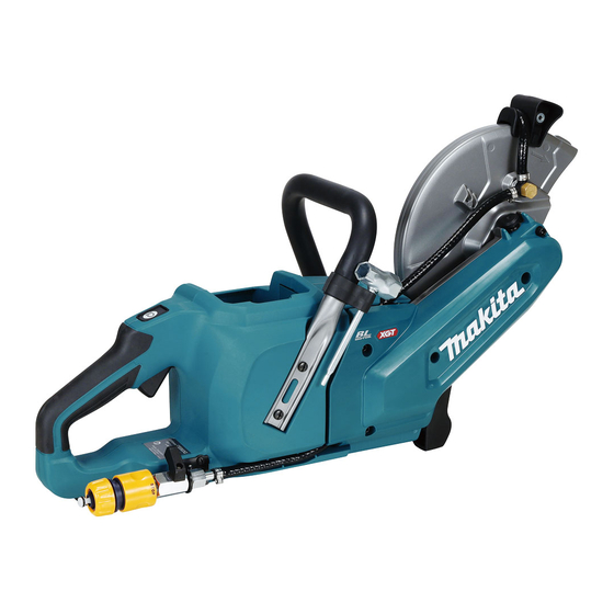
PARTS DESCRIPTION Fig.1 Abrasive cut-off wheel / Wheel cover grip Wheel guard Grip diamond wheel Battery cartridge Lock-off button Lamp Overload indicator Lamp button Switch trigger Handle Water inlet Cock Cover (for synchro-belt) Shaft lock button Coupling sleeve Box wrench (hex wrench-shaped han- dle tip) 8 ENGLISH... -
Page 9: Functional Description
Indicating the remaining battery FUNCTIONAL capacity DESCRIPTION Press the check button on the battery cartridge to indi- cate the remaining battery capacity. The indicator lamps CAUTION: Always be sure that the tool is light up for a few seconds. switched off and the battery cartridge is removed before adjusting or checking function on the tool. Installing or removing the battery cartridge CAUTION: Always switch off the tool before... -
Page 10: Overheat Protection
Protections against other causes operation and serious personal injury. Return tool to a Makita service center for proper repairs BEFORE further usage. Protection system is also designed for other causes that could damage the tool and allows the tool to stop To prevent the switch trigger from being accidentally pulled, a lock- automatically. Take all the following steps to clear the... -
Page 11: Electronic Function
Then remove the hex This tool is equipped with an electric brake. If the tool bolt, outer flange and wheel. consistently fails to quickly stop after the switch trigger is released, have the tool serviced at a Makita service center. Active Feedback sensing Technology The tool electronically detects situations where the wheel or accessory may be at risk to be bound. In the... -
Page 12: Connecting To Water Supply
Fig.12 the tool side as shown in the figure. ► 1 . Hex bolt 2. Flange 80 (black) 3. Ring 4. Abrasive cut-off wheel CE003G (for the abrasive cut-off wheel / diamond wheel) Connecting to water supply Prepare a water hose. Remove the nut on the coupling sleeve and pass the water hose through the nut. -
Page 13: Operation
Connect the water hose to the water supply. OPERATION When connecting to a water faucet, use a suitable fitting such as hose band or water tap joint. CAUTION: Be sure to hold the workpiece firmly down on a stable bench or table during operation. CAUTION: Do not twist or force the tool in the cut, or else the motor may be overloaded or the workpiece may break. -
Page 14: Maintenance
NOTICE: Never use gasoline, benzine, thinner, alcohol or the like. Discoloration, deformation or cracks may result. To maintain product SAFETY and RELIABILITY, repairs, any other maintenance or adjustment should be performed by Makita Authorized or Factory Service Centers, always using Makita replacement parts. Fig.19 ► 1 . Cock 14 ENGLISH... -
Page 15: Cleaning The Tool
Cleaning the tool Changing the synchro-belt After each use, remove the battery cartridge and the Remove the battery cartridge and the wheel. wheel and then clean dust, dirt or metal chips accu- Loosen the hex socket bolts using box wrench mulated inside the wheel guard. Clean the tool body handle and then remove the cover. by wiping off dust, dirt with a dry cloth or one dipped in soapy water and wrung out. Use a dry cloth to wipe the dirt off the lens of the lamp. Be careful not to scratch the lens of lamp, or it may lower the illumination. Fig.21 ► 1 . Wheel guard 2. Lens of the lamp Cleaning the air vent Regularly clean the tool's air vents or whenever the vents start to become obstructed. - Page 16 Push in the shaft lock button and hold it to lock the Hook the new synchro-belt on the teeth of the pulley (driven), turn the nut on the pulley (driven) coun- pulley (driven), with the teeth of the belt facing inside. terclockwise using the box wrench, and then remove Put the other end of the synchro-belt onto the pulley the nut and the plate on the pully. (driving) so that it is partially hooked on the teeth of the pulley. After that, move the synchro-belt around the pul- leys to the right. The synchro-belt will get on the track as you turn. Fig.25 ► 1 . Nut 2. Plate 3. Pulley (driven) 4. Box wrench 5.
- Page 17 Make sure that all the teeth on the internal circle Align the pins on the pulley (driving) and the holes of the synchro-belt fit into the teeth on the pulleys. Move in the plate firmly, then put the cover on and tighten the the synchro-belt around the pulleys and check for any hex socket bolts using box wrench handle. abnormal noise or vibration. Fig.29 ► 1 . Hex socket bolt 2. Cover 3. Plate 4. Box wrench (hex wrench-shaped handle tip) 5.
- Page 18 10. Place the cover onto the tool and tighten the hex socket bolts using the box wrench handle. Fig.31 ► 1 . Tube 2. Hex socket bolt 3. Cover NOTICE: Make sure that the tube for water feed is in the positions as shown in the figure before attaching the cover.
-
Page 19: Troubleshooting
Water is leaking from the O-ring part. Ask your local authorized service center for repair. OPTIONAL ACCESSORIES CAUTION: These accessories or attachments are recommended for use with your Makita tool specified in this manual. The use of any other accessories or attachments might present a risk of injury to persons. Only use accessory or attachment for its stated purpose. - Page 20 Makita Europe N.V. Jan-Baptist Vinkstraat 2, 3070 Kortenberg, Belgium Makita Corporation 3-11-8, Sumiyoshi-cho, Anjo, Aichi 446-8502 Japan 885A73-224 20240126...
Need help?
Do you have a question about the CE003G and is the answer not in the manual?
Questions and answers