Table of Contents
Advertisement
Quick Links
Advertisement
Table of Contents

Related Manuals for Casio Cassiopeia E-200


Summary of Contents for Casio Cassiopeia E-200
- Page 1 (without price) Pocket PC E-200 DEC. 2001 E-200 INDEX Ver.1 MARCH/ 2002...
-
Page 2: Table Of Contents
CONTENTS 1. SPECIFICATIONS ------------------------------------------------------------------------------------- 1 2. OPTION --------------------------------------------------------------------------------------------------- 2 3. OPTION COMBINATION ----------------------------------------------------------------------------- 4 4. Required System Configuration ----------------------------------------------------------------- 5 5. GENERAL GUIDE ------------------------------------------------------------------------------------- 7 5-1. Guidance of each functions ------------------------------------------------------------------- 7 5-2. Initial Setup ----------------------------------------------------------------------------------------- 8 5-3. Opelation -------------------------------------------------------------------------------------------- 9 5-4. -
Page 3: Specifications
1. SPECIFICATIONS Model: E-200 × Display: 320 dots TFT Color LCD (65,536 colors) ® CPU: Intel StrongARM Processor (206 MHz) Memory: ROM 32 MB Flash ROM RAM 64 MB Interfaces: Serial: RS-232C, 115.2 kbps max. Infrared: IrDA Ver. 1.2 Range: 20 cm max. USB (Host/Client) Card Slot: CompactFlash card, 3.3 V Type I / Type II... - Page 4 2. OPTION For Pocket PC 2002 CASSIOPEIA E-200 Battery & Power Adapter AC Adapter Attach it directly to the E-200 or to the E-200 cradle to provide power and recharge the batteries. • AD-C54240E Lithium Ion Rechargeable Battery Keeps your E-200 colour screen powered for an extended period.
- Page 5 Screen Protectors Helps protect your screen from pen and pencil damage. 5 sheets are included. • JK-834PS5 PC Card Unit Accepts PCMCIA TYPE II Cards. • JK-864PU Stereo Earphone with Remote Control For use with music, while reading E-mail and E-book with the remote control. •...
-
Page 6: Option Combination
3. OPTION COMBINATION 32pin→20pin/USB CASIO 20pin 233C Serial Cable Attachment (Option) USB TypeA 32pin USB Cable(Option) DOS/V USB Cradle USB TypeA (Included) USB TypeA USB Cradle/Cable Expansion Unit 32pin (Option) PCMCIA type II CARD USB TypeA USB Mach. Wireless CARD... -
Page 7: Required System Configuration
4. Required System Configuration ® The minimum system configuration required for running ActiveSync 3.5 is described below. Microsoft ® ActiveSync ® 3.5 System Requirements Minimum Desktop Computer Requirements ® ® ® ® ® ® • Microsoft Windows XP, Microsoft Windows 2000, Microsoft Windows ®... - Page 8 Note • Different minimum system requirements are required when using the applications included on the CASSIOPEIA Applications CD-ROM . See the documentation contained on the CD-ROM for full details. • The cradle that comes with the unit is designed for USB connection only. If your computer does not have a USB port, necessary to purchase the separate 20Pin/USB host Converter (JK-744CV) and the serial connection cable (JK-580CA), which allow direct connection between the unit and connected computer’s serial port.
-
Page 9: General Guide
5. GENERAL GUIDE (Quotation from E-200 Hardware Manual) 5-1. Guidance of each functions CompactFlash Card slot Charge indicator (Amber/Green) Indicator lamp (Red) Infrared port Stylus Microphone Stereo headphone jack Power button Touch screen Reset button Cursor button Action control SD Memory/ MMC Card slot Speaker •... -
Page 10: Initial Setup
5-2. Initial Setup After first unpack of the unit, perform the following initial setup procedure before using it for the first time. 1. Load the main battery (rechargeable battery pack). • Be sure to use the AC Adapter to charge the battery pack before doing anything else. The unit will not be operated correctly if the backup battery is loaded before charging the battery pack. -
Page 11: Opelation
5-3. Operation Using the Stylus Data input and virtually all other operations are performed using a stylus, which is housed inside the stylus holder in the right corner of the unit. • Use only the stylus that comes with the unit, or some other stylus type instrument with a soft, blunt point to perform touch screen operations. - Page 12 Connecting the Cradle to a Computer The cradle has a USB cable for connection to a computer. Connect the end of the cable to a USB port of the connected computer. • See "Required System Configuration" on page 5 for details on the type of computer system required for use with the cradle.
- Page 13 4. Taking care to align the serial connector on the bottom of the unit with the connector on the cradle, lower the unit into the cradle as shown in the illustration below. Make sure the unit lowers securely into the cradle as far as it can go. To remove the CASSIOPEIA from the cradle Pull up on the unit so the recess on its back disengages from the raised part of the cradle, and then lift the unit straight up from the cradle.
- Page 14 Using the USB Cable The USB cable to connect the unit directly to a computer. • See "Required System Configuration" on page 5 for the computer system that is required for direct USB connection. • The illustration below is just one possible connection configuration. The location and layout of USB ports vary from computer to computer.
- Page 15 Infrared Communication The infrared port of this unit can be used to exchange data with another unit, or with another device equipped with infrared communication capabilities. Remember that the two infrared ports must be pointed directly at each other when performing communication. The distance between the two infrared ports must be less than 20 cm.
-
Page 16: Software Applications
Using a PC Card Unit (Option) The PC Card Unit makes it possible to use PCMCIA type cards with the unit. An optionally available battery pack can also be installed on the PC Card Unit and used as an external power supply for the unit. See the user documentation that comes with the PC Card Unit for details about using it. -
Page 17: Battery & Reset
6. BATTERY & RESET (Quotation from E-200 Hardware Manual) 6-1. Batteries The unit is powered by a dual power supply that consists of a main battery (rechargeable battery pack) and a backup battery (CR2032 lithium battery). Main (Backup) Battery Recharge (Replace) the battery pack (backup battery) as soon as possible after the following message appears. "Main (Backup) Batteries Very Low To prevent possible data loss, replace or recharge the main batteries according to the owner’s manual."... -
Page 18: Full Reset (Memory Initialize)
Memory Error Message If the memory check operation that the unit performs when the reset button is pressed detects a data error, the following message appears on the screen instead of the startup screen. "A problem with memory contents has been found. Press [Action] to continue with the reset procedure, which restores normal system operation. -
Page 19: Operation Check
7. OPERATION CHECK 7-1. Preparation 1. E-200(Prepare another units to perform IrDA communication check except the checking unit.) 2. Compact Flash Memory Card (recommended more than 32MB type, at least 8MB type required) 3. SD Memory Card 4. Rechargeable Battery Pack 5. -
Page 20: How To Boot The Diagnostic Program
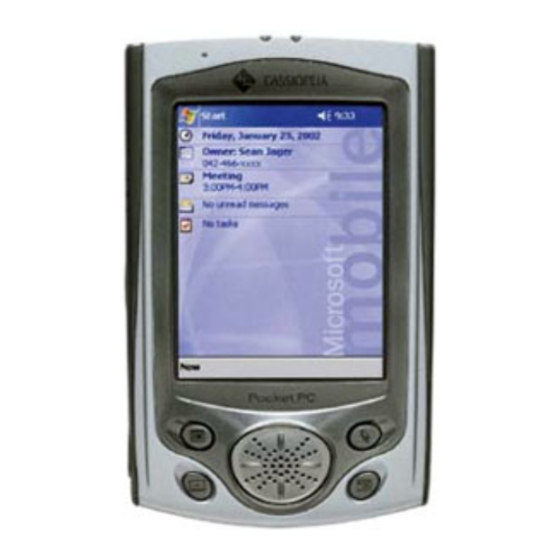
7-3. How to boot the diagnostic program < HOW BOOT AND CHECK THE PROGRAM > Seq. Operation Display Initial display (welcome) comes up after Perform full reset full reset Peform initial set up Today Screen (Microsoft mobile) comes (Refer to 5-2. Initial Setup of page 8) The test menu is booted automatically PQAP 2:24... -
Page 21: Operation Check
7-4. Operation Check Touch Panel Touch Panel should be checked. Operation Display Check If NG Check the item which you want Touch Test Items Corners Test to test and tap "Start". Panel, Cross Test Main Start Exit Corners Test If the four marks do not Tap on the four points at corners. - Page 22 Button Button should be checked. Operation Display Check If NG Check if the unit correctly counts Confirm the number every Button the number of times the buttons pressing button PCB, in the right fiture are pressed. Main Tapping "Reset" clears the PCB, number.
- Page 23 Audio Audio should be checked. Operation Display Check If NG Check the item which you want Check if the sounds are normal. Speaker, Play Test to test and tap "Start". 500 Hz Main 1 KHz Note: L-ch and R-ch sound can 2 KHz be test if remote earphone is Record Playback Test...
- Page 24 Power Not used. IrDA IrDA should be checked. Operation Display Check If NG TEST UNIT Check the item which you want Main Test Items to test and set local mode Connect Test "client". Transfer Test Config Settings Local Mode Client Run until stop Start Exit...
- Page 25 LED should be checked. Operation Display Check If NG Tap "Start." Main Action Start Stop Click "Start" to flashing LED. Click "Stop" to stop flashing LED. Test Result Click "PASS" if LED is work properly. Otherwise, click "FAILED". PASS FAILED Indicator lamp flashes.
- Page 26 FlashCard FlashCard should be checked. Operation Display Check If NG Test Items Check the item which you want Check on test result "Pass". Relevant CF Card Write/Read Test to test and tap "Start". card SD Card Write/Read Test PC Card Write/Read Test Bulit-in Storage Write/ Read Test Options...
- Page 27 OsVer OS version should be checked. Operation Display Check If NG Information on OS version is Version Testing indicated. Expect Curent OS version 1087 1070 Checksum 76240 71073 Result : Failed Auto exit after checking. Messages: E-Boot version=1.51 Exit Tap "Exit." Panel Sign Panel sign shouldbe checked.
- Page 28 SD_Detect SD card detection should be checked. Operation Display Check If NG Insert SD card. Main SD Card is removed, Please INSERT SD Card now. Auto exit after tested. Failed & Exit Remove SD card. Check it the test is PASS. PASS Auto exit after tested.
-
Page 29: Adjustment
8. ADJUSTMENT Display quality adjustment When flickers and vertical stripes appear in the screen, perform this adjustment according to the following procedure. 1. Disassemble side panel and upper case in accordance with DISSASSEMBLY PROCEDURE of this manual. 2. Put the main PCB as shown below finger, and confirm the position of adjustment volume. 3. -
Page 30: Trouble Shooting
9. TROUBLE SHOOTING 9-1. Hardware No power at all Possible cause Recommend action Main battery discharged Recharge the battery Internal data corruption (F-ROM/RAM) Perform full reset Wrong position of battery cover switch Set proper position AC adaptor fault Replace AC adapotor No main battery is set with AC adaptor Set main battery during any operation Terminals of main battery are dirty... - Page 31 No front light (Other fanctions OK) Possible cause Recommend action Poor contact of inverter connector Reconnect inverter connector CN1 and CN2 Faulty inverter PCB Replace the inverter PCB Faulty lamp in LCD module Replace the LCD module No display/No front light (other functions OK) Possible cause Recommend action Poor soldering of connector at main PCB...
- Page 32 Data error/memory corruption message Possible cause Recommend action Internal data malfunction (corruption) Reset (or full reset) the unit Weak of main and sub battery Check voltage of main and sub battery Improper pocket TV application software Check the matching of application software Faulty internal PCB Replace RAM PCB Poor soldering of RAM...
-
Page 33: Software
Backup data cannot be reloaded by Card Backup Tool or ActiveSync Possible cause Recommend action No Card Bacup Tool installed Install the application from Casio CD-ROM No service patch software installed Install the service patch software from Web Error at Built-in strage access after dial up... -
Page 34: Support Pocketpc 2002
9-3. Support for PocketPC 2002 1. IMAP4 When you are using an IMAP4 mail server, note that the mail messages on your server cannot be deleted from the Inbox. In this case, you need to connect to your server with another computer and delete the mail messages on the server. -
Page 35: Wiring Diagram
10. WIRING DIAGRAM — 33 —... -
Page 36: Pcb View
11. PCB VIEW BC135 BC136 R145 R150 R197 R196 R160 R161 TC10 TP15 TP16 TP17 BC143 BC145 BC144 BC146 R195 BC147 BC148 R165 R169 R173 R202 R182 R183 R187 R188 R189 R191 R193 BC165 — 34 —... - Page 37 MIC1 MARK3 PAD1 R153 U10 U11 BC20 BC21 R154 R194 BC24 BC27 BC29 BC38 BC30 BC31 BC32 BC33 BC35 BC34 BC37 R43 R44 BC55 BC40 BC43 R204 BC50 BC51 BC47 BC52 BC53 BC54 BC57 MARK1 U27 U28 R199 R198 PAD2 BC55 BC74 BC71 BC72...
-
Page 38: Disassembly/Assembly Procedure
12. DISASSEMBLY/ASSEMBLY PROCEDURE 12-1. DISASSEMBLY Disassembly the unit according to the following procedure. 1. Remove CF dummy card, Stylus pen. After sliding the battery cover switch to left and right, remove the battery covers, lithium battery and rechargeable battery in order. 2. - Page 39 5. Disassemble other side cover as same as 4. Adhesive tape at this side 6. Remove 6 screws from the case. 7. Unhook and separate the upper and lower cases by using case opner as shown figure. Hook Hook 8. Separete the upper and lower case, and main PCB, LCD module and button PCB must be the upper case side.
- Page 40 9. Put the upper and lower case as shown figure. And disconnect the backup battery, speaker and button PCB cable. Disconnect 10. Remove main PCB and LCD module from upper case as shown figure. 11. Remove LCD module from main PCB as shown figure. Unscrew Disconnect 12.
- Page 41 13. Separate the shield plate from LCD module carefully by using case opener. Spare parts of LCD module dose not include the shield plate, and shild paper and insullation seal on LCD cable. 14. The repair is available as set of Main PCB + Inverter PCB + RAM PCB. The details will be informed by Service Bulletine separately.
-
Page 42: Assembly
17. Remove 4 screws, and separete the button PCB. Screws Screws 18. Remove Speaker and the cover as shown figure. 12-2. ASSEMBLY Assembly the unit according to the following procedure. 1. Assemble speaker and the cover, then put them as shown figure. Speaker wires Be careful the position of speaker wires. - Page 43 3. Connect the FPC and cable connector. Put LCD moldule as FPC between shown arrow on the main PCB. Make sure end of LCD shield main and button PCB plate must be fit at end of main PCB. Inverter connector Put cap 4.
-
Page 44: Parts List
15. PARTS PRICE LIST * Refer to the lower table concerning Applicable in Parts LIst. Applicable Shipment USA and Canada Europe Others Price Code Item Code No. Parts Name Specification Applicable PCB ASSY/MAIN 9481 1128 JACK/HEADPHONE 22.10088.281 Common 9481 1129 JACK/DC 22.10133.381 Common 9481 1130 BUTTON/POWER... - Page 45 1. The following described in Tentative Service Manual can not be supplied. Item Code No. Parts Name Specification Applicable 1007 5949 COVER/BACKUP BATTERY 42.30S11.001 Common 1007 5952 COVER/MAIN BATTERY 42.30S09.001 Common 1007 5977 SCREW 86.00099.3Q0 Common SOFTWARE/CD-ROM(CASIO) CDJ710AA02A Common SOFTWARE/CD-ROM(CASIO) CDJ710AA03A Common SOFTWARE/CD-ROM(CASIO) CDJ710AA04A Common - 43 -...
- Page 46 2. The following parts decribed in Tentative Service Manual will not be supplied in the near future, and are interchanged now as shown below. Parts described in Tentative Interchanged Parts Service Manual Stock (in Parts Name I t e m Code No. Specification I t e m Code No.
-
Page 47: Exploded View
14. EXPLODED VIEW (COMPONENTS) Note: Refer to the descriptions in Parts (Price) List. Spacers ∗ Refer to the next page concerning M1~M4. Insulation sheet ∗ Only battery Aluminium sheet compartment covers can not be supplied. ∗ Rating Label is stuck on the lower case. - Page 48 (PCB ASSY/MAIN) — 46 —...
- Page 49 (OTHERS) — 47 —...
- Page 50 Ver.1 : • "7. DATA BACKUP" has been deleted • Deletion of spare part (Item28) in PARTS LIST (page 42) and EXPLODED VIEW (page 45) CASIO TECHNO CO.,LTD. Overseas Service Division Nishi-Shinjuku Kimuraya Bldg. 1F 5-25, Nishi-Shinjuku 7-Chome Shinjuku-ku, Tokyo 160-0023, Japan...
Need help?
Do you have a question about the Cassiopeia E-200 and is the answer not in the manual?
Questions and answers