Table of Contents
Advertisement
Quick Links
RWE-PWE Kc/ Ka /Kr
WATER COOLED CHILLERS AND HEAT PUMPS WITH SCROLL COMPRESSORS
►
Chillers and heat pumps.
►
Packaged internal installation.
►
Scroll compressors.
►
Waterside cycle inversion.
►
Maximum efficiency at lower sound emission.
►
Wide range of option.
Use and maintenance Book
Rev. 2.0 03/21
Range 50-475 kW
Advertisement
Table of Contents

Related Manuals for Emicon RWE-PWE Kc Series


Summary of Contents for Emicon RWE-PWE Kc Series
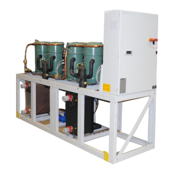
- Page 1 RWE-PWE Kc/ Ka /Kr WATER COOLED CHILLERS AND HEAT PUMPS WITH SCROLL COMPRESSORS Range 50-475 kW ► Chillers and heat pumps. ► Packaged internal installation. ► Scroll compressors. ► Waterside cycle inversion. ► Maximum efficiency at lower sound emission. ► Wide range of option.
-
Page 2: Table Of Contents
___________________________________ RWE/PWE Kc – Ka – Kr _________________________________ SUMMARY INTRODUCTION Note Symbols Reference laws and norms Identification tag Warranty Manual receiver Personnel requirement Dangerous areas DESCRIPTION Nomenclature RWE – PWE Kc-Ka-Kr Series Version Models with partial and total heat recovery (RP / RT option) Main components Factory tests Options... - Page 3 ___________________________________ RWE/PWE Kc – Ka - Kr _________________________________ 5.1.4 Check of fluid to be refrigerated 5.1.5 Noise and vibration check 5.1.6 Leakage sensor check and calibration Ordinary Maintenance 5.2.1 Overcurrent protection devices check 5.2.2 Contactors check 30-31 Troubleshooting 32-33 Extraordinary Maintenance DEMOLITION AND DISPOSAL...
-
Page 4: Introduction
___________________________________ RWE/PWE Kc – Ka - Kr _________________________________ INTRODUCTION The RWE/PWE Kc – Ka - Kr Series units, operating with R410a (Kc), R134a (Ka) e R454B (Kr) refrigerants, are water cooled chillers and heat pumps, with high efficiency plates exchanger and hermetic scroll compressors working on single circuit or double circuit, single or tandem configuration, depending on the cooling capacity of the unit. They are suitable for indoor installations, particularly indicated for small or medium sized air-conditioning systems, servicing multiple dwellings or commercial installations where a water ring for heat disposal is available. -
Page 5: Identification Tag
___________________________________ RWE/PWE Kc – Ka - Kr _________________________________ Identification Tag The unit is identified by an indelible label on the external panel of the electrical cabinet (henceforth Identification Tag). Here below an example of the Identification Tag, showing and describing all the information, in compliance with the applicable European directives. Name and address of Manufacturer CE mark and the Notified Organization identification number which released the PED... -
Page 6: Warranty
___________________________________ RWE/PWE Kc – Ka - Kr _________________________________ Warranty The Manufacturer guarantees the unit, in compliance with his Sales Conditions and, eventually, with the contract agreements. The Manufacturer warranty will decay if you are not scrupulously respecting the instructions of this Handbook. The Manufacturer declines any responsibility for possible damages to people, animals, objects or environment due to any wrong installation, maintenance or regulation, i.e. -
Page 7: Description
___________________________________ RWE/PWE Kc – Ka - Kr _________________________________ DESCRIPTION Nomenclature In the following scheme, it is explained the meaning of the device name acronym 1 Kc-Ka-Kr CALORE R-Chiller / P-Heat pump W-CONDENSAZIONE AD ACQUA W-Watercooled E-COMPRESSORE ERMETICO SCROLL E-Ermetic scroll compressor 51-RESA FRIGO NOMINALE (kW) 51-Nominal cooling capacity... -
Page 8: Main Components
___________________________________ RWE/PWE Kc – Kr - Ka _________________________________ Main components FRAME The structure is built by robust steel pressed and bent profiles, and then painted in RAL 7035 colour. All the unit’s components, including the accessories available (such as the additional heat exchanger for the partial or total recovery of the condensation heat RP or RT) are integral with the structure and mounted on sight. - Page 9 ___________________________________ RWE/PWE Kc – Kr - Ka _________________________________ ELECTRICAL BOARD The electrical cabinet of the unit is realized in compliance with current European Standards inside a metal compartment with protection degree IP54 suitable for external installation and separated from airflow. The main features are: •...
-
Page 10: Factory Tests
___________________________________ RWE/PWE Kc – Ka – Kr _______________________________ SCROLL SOUND PROOFING CABINET COMPRESSORS (CF/CFU OPTIONAL) ELECTRIC PANEL PLATES CONDENSER PARTIAL OR TOTAL RECOVER EXCHANGER (RP / RT OPTIONS) PLATES EVAPORATOR Factory Tests Once ready, the circuit is subject to a mechanical pressure test, according to the procedures indicated in the Quality System, and a check of the eventual leakage. Before delivery, we carry out a functional test of the chiller. -
Page 11: Options
___________________________________ RWE/PWE Kc – Ka - Kr_________________________________ Options Here below the main options which for RWE /PWE Kc-Ka-Kr series: Amperometer: Electrical device to measure the absorbed electrical current intensity; Electrical power different than standard: Especially 230V three phase, 460V three phase. Frequencies 50/60 Hz Soundproofed compressors cabinet with standard material: Compressors soundproofed case made of extruded and anodized aluminium profiles, padded with aluminium alloy panels, covered with ashlar-like sound-absorbing material Soundproofed cabinet with bituminous rubber material: Cabinet made of extruded and anodized aluminium profiles, padded with aluminium alloy panels, covered... -
Page 12: Functional Diagram
___________________________________ RWE/PWE Kc – Ka - Kr_________________________________ Functional diagram COOLING CIRCUIT DIAGRAM OF RWE/PWE Kc-Ka- Kr (with some available options) COOLING CIRCUIT DIAGRAM OF RWE/PWE Kc-Ka-Kr + RT (with some available options) LEGEND Scroll compressors High pressure gauge Plates condenser Low pressure gauge Anti-freeze heater Safety switch... -
Page 13: Wiring Diagram
___________________________________ RWE/PWE Kc – Ka - Kr _________________________________ Wiring diagram The wiring diagrams of control unit and power, terminals and the resume tab of components, is attached to the Manual Sound emission The unit does not required operators presence cause is able to operate in total autonomy. Is not necessary provide sound emission data;... -
Page 14: Installation
___________________________________ RWE/PWE Kc – Ka - Kr _________________________________ INSTALLATION The unit installation must comply with local existing laws and regulations. Identification The unit is identified by the Identification Tag, described above, attached inside of the electric cabinet. The correct unit identification by means of the serial number is essential for the execution of any operation to carry out on the unit. You always have to advise the serial number of the unit whenever submitting a request of Manufacturer technical service support. -
Page 15: Positioning
___________________________________ RWE/PWE Kc-Ka- Kr _________________________________ Positioning The unit’s owner is responsible for expenses of installation, and he must supervise the execution operation. The execution of a correct installation presupposes than a plan has been drawn up by an expert and that is carried out by skilled trained technicians. The area used to install the unit, there must be no aggressive substance or not compatible with copper, carbon steel, aluminium and other materials which are used in its construction. -
Page 16: Hydraulic Circuit
___________________________________ RWE/PWE Kc-Ka-Kr _________________________________ Hydraulic circuit The unit is designed for connection to a chilled and / or hot water distribution network, depending on whether they are chiller or heat pumps. A skilled contractor must realize the piping. The fluid must not contain aggressive substances or not compatible with copper, carbon steel, aluminium and other materials which are used in its construction. It is necessary to carry out chemical analysis in case of doubt and to send the result to the Manufacturer, so to commonly agree the necessary measures. -
Page 17: 3.5.2 Hydraulic Connections - Evaporator
___________________________________ RWE/PWE Kc-Ka-Kr _________________________________ The machine must be connected to the hydraulic circuit by an expert and qualified technician, in compliance with the local Regulations in force It is important the chilled liquid flows in the correct direction into the evaporator. The pipes must be joined following the indication given on the connections point of the unit. -
Page 18: Heat Pumps Hydraulic Connections - Pwe Kc-Ka-Kr Series Version
___________________________________ RWE/PWE Kc-Ka-Kr _________________________________ 3.5.4 HEAT PUMPS HYDRAULIC CONNECTIONS - PWE Kc-Ka-Kr SERIES In case of heat pumps (PWE Kc-Ka-Kr Series) with the cycle inversion on the hydraulic circuit, the following situation occurs: • Summer operation: the chilled water produced in the evaporator is sent for use, while the hot water produced in the condenser is sent to the exchanger in which it can dissipate the accumulated heat. -
Page 19: Chemical-Physical Properties Of Water
___________________________________ RWE/PWE Kc-Ka-Kr _________________________________ 3.5.5 CHEMICAL-PHYSICAL PROPERTIES OF WATER In the following table, you can find, just as an indication, the main values of chemical and physical properties of the water to be respected to avoid corrosion or any sediment. To this purpose, it is advisable a yearly check of the PH stability. -
Page 20: Hydraulic Circuit Filling
___________________________________ RWE/PWE Kc-Ka-Kr _________________________________ 3.5.6 HYDRAULIC CIRCUIT FILLING Once the hydraulic circuit is done, the unit connected and the system seal test performed, fill the circuit, following the here below described steps: Open all the vent valves on the circuit; Connect the circuit, if possible permanently, to the water supply system, using an automatic filling group provided with a manometer and a check valve;... -
Page 21: Electric Connections
___________________________________ RWE/PWE Kc-Ka-Kr _________________________________ Electrical connections The electrical power supply must be sized by a qualified engineer and realized by qualified technicians, on behalf of the Owner, in compliance with current local regulations. The supply cable upstream the unit must be protected by an automatic switch with suitable size and features and in compliance with current local dispositions. The system must be realized in order to cut-off the power supply of the unit, without stopping other services like lightening, ventilation, alarms and safety systems. -
Page 22: Freon Safety Valves
___________________________________ RWE/PWE Kc-Ka-Kr _________________________________ Inside the electrical cabinet, there is a terminal box with digital and analogue signals for the unit operations. Since the terminal configuration can be different in each singe unit, refer to the one shown in the wiring diagram enclosed in the Handbook. As an example, here below you can find the pre-arranged terminals for free contacts described in the table. -
Page 23: Rwe/Pwe Kc-Ka-Kr Application Range
___________________________________ RWE/PWE Kc-Ka-Kr _________________________________ RWE / PWE Kc-Ka-Kr application range The nominal water flow of the standard unit is referred to a Delta T 5K between inlet and outlet, in relation to the cooling capacity. RWE / PWE Kc UNITS MODEL 511 Kc 611 Kc... -
Page 24: Operation
___________________________________ RWE/PWE Kc-Ka-Kr _________________________________ OPERATION Before its commissioning, the operational staff must be instructed, also by means of this Handbook, on the unit manufacture, management, operation and maintenance, on safety measures and regulations to respect, as well as on any personal protective equipment to arrange, properties and indications to handle the used refrigerant. -
Page 25: First Start-Up
___________________________________ RWE/PWE Kc-Ka-Kr _________________________________ Periodically verify that the mechanical filter is clean, to prevent a decrease of the fluid to be cooled flow rate due to excessive pressure drops. During unit operation, the hydraulic system pressure must be always be between 1,5 and 3,5 bar. •... -
Page 26: Switching Off
___________________________________ RWE/PWE Kc-Ka-KR _________________________________ 4.3.2 SWITCHING OFF To stop the unit, press the ON/OFF button on the microprocessor keyboard, and switch it to OFF: If you foresee to keep the machine OFF for more than 24 hours, then turn the main switch in OFF position so to cut off the power supply. In the event of any anomaly detected during unit operation, you must solve it as soon as possible, in order to avoid they are still present when switching Microprocessor regulation In order to change microprocessor settings, follow the instructions on the microprocessor documentation attached in the Handbook. -
Page 27: Maintenance
___________________________________ RWE/PWE Kc-Ka-Kr _________________________________ MAINTENANCE The Owner is responsible to maintain the unit properly as indicated in the Handbook and as required by current local Laws and Regulations. Qualified and trained personnel, equipped with personal protective devices, as required by current local Laws and Regulation in force, must carry out the unit maintenance. -
Page 28: Leak Detection
___________________________________ RWE/PWE Kc-Ka-Kr _________________________________ CASE Sight inspection Pressure test Leak detection (par. 4.2, p.ti a – l) Inspection, after air intervention, with possible effects on the mechanical resistance or after a change of use or after a stop longer than 2 years; all non-proper components must be replaced. -
Page 29: Ordinary Maintenance
- Check of basic setting values; - Control and calibration check with test gas; to perform this test it is necessary to buy calibration kit or uninstall the sensor to send it to Emicon AC SpA. To carry out the test, it is possible to buy the kit provided by the Manufacturer MSR Electronic GmbH, Wurdinger Str. 27a – 94060 Pocking – Germany; in any case refer to sensor Manual you can find on-board of the unit. -
Page 30: Contactors Check
_________________________________ RWE/PWE Kc-Ka-Kr _________________________________ 5.2.2 Contractors check You must check contactors used to activate electrical loads to control their integrity, contacts condition and the coil functionally. Please also verify that electrical cables are strongly and rightly connected to their terminals. If required, remove dust and debris, which can cause a noisy and unreliable operation of the device. - Page 31 ___________________________________ RWE/PWE Kc-Ka-Kr _________________________________ FREQUENCY ACTIONS Daily Monthly Every 2 months Every 6 months Once a year Every 5 years If required COMPRESSORS Visually inspect compressors Check compressors noise and vibration Check compressors supply voltage Check the compressors electrical Connections Check the conditions of the compressors Electrical cables and their connections to the terminals...
-
Page 32: Troubleshooting
___________________________________ RWE/PWE Kc-Ka-Kr _________________________________ Trouble shooting The microprocessor is detecting failures occurring during the operation and, besides signalling alarms, it also shows the type of active failure. The hereafter table reports the most common malfunctioning, and for each one of the most probable causes and possible solutions. In case of alarm, before any intervention, verify that: •... - Page 33 ___________________________________ RWE/PWE Kc-Ka- Kr _________________________________ FAILURE PROBABLE CAUSE SUGGESTED ACTION a) The low pressure switch is not set properly Replace the low pressure switch b) The cooled water flow capacity is not sufficient See point 4 6. The low pressure switch is activated c) Suction pressure too low See point 10...
-
Page 34: Extraordinary Maintenance
___________________________________ RWE/PWE Kc-Ka-Kr _________________________________ Extraordinary maintenance Qualified and trained personnel, equipped with individual protection devices in compliance with current local laws and regulation, must repair the unit. You cannot carry out any modification on the unit or any components replaced, without Manufacturer’s explicit authorization. Any intervention made by technicians with specific skills (welders, electricians, programmers, etc) must be carried out under the supervision of personnel expert in refrigeration field. - Page 35 ___________________________________ RWE/PWE Kc-Ka-Kr _________________________________...
Need help?
Do you have a question about the RWE-PWE Kc Series and is the answer not in the manual?
Questions and answers