Table of Contents
Advertisement
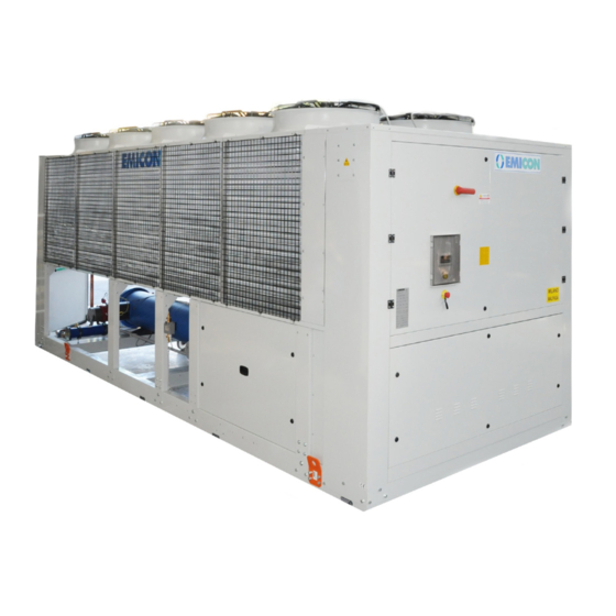
RAH - PAH Ka
AIR CONDENSED CHILLERS AND HEATPUMPS WITH SCREW
COMPRESSORS AND AXIAL FANS
►
Chillers and heatpumps
►
Screw compressors
►
Shell & Tube exchanger
►
Electronic expansion valve
►
Axial fans
►
High efficiency at partial loads
►
Compact dimensions
►
Wide range of options
Use & Maintenance Book
Rev. 1.2 10/18
Range 387-1211 kW
Advertisement
Table of Contents

Related Manuals for Emicon RAH


Summary of Contents for Emicon RAH
- Page 1 RAH - PAH Ka AIR CONDENSED CHILLERS AND HEATPUMPS WITH SCREW COMPRESSORS AND AXIAL FANS Range 387-1211 kW ► Chillers and heatpumps ► Screw compressors ► Shell & Tube exchanger ► Electronic expansion valve ► Axial fans ► High efficiency at partial loads ► Compact dimensions ► Wide range of options Use & Maintenance Book Rev. 1.2 10/18...
-
Page 2: Table Of Contents
Pumps group P1/P2- RAH S Ka series 3.6.3 Pumps group P1H/P2H - RAH Ka series 3.6.4 Pumps group P1H/P2H - RAH S Ka series 3.6.5 Pumps group PT- RAH Ka series 3.6.6 Pumps group PT - RAH S Ka series 3.6.7... - Page 3 ___________________________________RAH / PAH Ka_________________________________ Preliminary checks Start up 4.3.2 Winter Stop 4.3.3 Switching off Microprocessor regulation MAINTENANCE Programmed Maintenance 5.1.1 Leak detection 5.1.2 Safety pressure switches check 5.1.3 Safety valves check 5.1.4 Fluid to be cooled check 5.1.5 Noise and Vibration check Ordinary Maintenance 5.2.1 Overcurrent protections device check...
-
Page 4: Introduction
If any doubts arises on the correct understanding of the instructions of this Handbook, please contact EMICON A.C.S.p.A (henceforth the Manufacturer) for clarification. The unit must be installed, managed, serviced, repaired and disposed in compliance with local regulations and laws in force. -
Page 5: Identification Tag
___________________________________RAH / PAH Ka_________________________________ 1.4 Identification Tag The unit is identified by an indelible label on the external panel of the electrical cabinet (henceforth Identification Tag). Here below an example of the Identification Tag, showing and describing all the stated information, in compliance with the applicable European directives. Manufacturer’s name and ... -
Page 6: Warranty
___________________________________RAH / PAH Ka_________________________________ WARRANTY The Manufacturer guarantees the unit, in compliance with what stated on its Sales Conditions and with what explicitly agreed in the contract, if present. The Manufacturer warranty will decay if the instruction of this Handbook won’t be scrupulously followed. The Manufacturer declines any responsibility for possible damages to people, animals, things or environment due to any miss-installation, maintenance or regula- tion, i.e. -
Page 7: Description
MODELS WITH TOTAL HEAT RECOVERY (RT) Each model of RAH Ka series, on demand, is available in total heat recovery version (Option RT). In this configuration, each cooling circuit is equipped with a refrigerant/water exchanger on gas discharge side. This exchanger, installed in parallel to the air condenser, is sized to recover 100% of the condensing heat to produce hot sanitary water or for other heating applications. -
Page 8: Main Components
In the low noise version (RAH S Ka), in order to reduce the sound level, the electrical connection is of star type, reducing thereby the rotation speed and con- sequently the air flow to the coil. - Page 9 ___________________________________RAH / PAH Ka_________________________________ ELECTRICAL BOARD The electrical cabinet of the unit, is realized in compliance with current European Standards inside a metal compartment with protection degree IP54 suitable for external installation and separated from airflow. The main features are: - Three-phase power supply 400 V/ 3ph / 50 Hz on all the models(if not differently required);...
-
Page 10: Tests
___________________________________RAH / PAH Ka_________________________________ AXIAL FANS CONDENSING COILS ELECTRICAL BUFFER TANK HYDRONIC PUMP SCREW COMPRESSOR CABINET (OPTION - MV) (OPTION – P1) FREON COIL SHELL&TUBE EVAPORATOR TEST Once the unit is completed, its circuit is submitted, following the directives stated in the Manufacturer’s quality warranty system, to a mechanical sealing test and to a leak test to find leakages if present. -
Page 11: Options
___________________________________RAH / PAH Ka_________________________________ OPTIONS Here below the main options which could be installed in RAH/PAH Ka series: Amperometer: Electrical device to measure the absorbed electrical current intensity. Electrical power supply different than standard: Especially 230 V three-phase, 460 V three-phase. Frequencies 50/60 Hz. Low ambient temperature operation (down to -8°C): Voltage-cut off Electronic device for the continuous modulating voltage control of the condensing pressure through the variation of the fan rotation speed, allowing unit operation till -8°C (Alternative to BF and EC). - Page 12 Total heat recovery: (100%) of condensing heat by refrigerant/water heat exchanger in alternative and in parallel to the condensing air section. It is used when you want to completely recover condensing heat for producing sanitary water or for heating applications (available for RAH Ka range).
-
Page 13: Functional Diagram
___________________________________RAH / PAH Ka_________________________________ 2.7 Functional diagram RAH KA COOLING CIRCUIT DIAGRAM (WITH SOME AVAILABLE OPTIONS) LEGEND screw compressors PDSW Water differential flow switch Condenser high pressure gauge Axial fans Low pressure gauge Antifreeze electrical heater Safety valves Crankcase heater High pressure switch Solenoid valve Low pressure switch Fans speed regulator... - Page 14 ___________________________________RAH / PAH Ka_________________________________ PAH KA COOLING CIRCUIT DIAGRAM (WITH SOME AVAILABLE OPTIONS) LEGEND Air/Freon exchanger PDSO Oil level safety switch screw compressors PDSW Water differential flow switch Axial fans high pressure gauge Antifreeze electrical heater Low pressure gauge Crankcase heater Safety valves Solenoid valve High pressure switch Fans speed regulator Low pressure switch 4 way valve for cycle inversion...
- Page 15 ___________________________________RAH / PAH Ka_________________________________ AVAILABLE CONFIGURATIONS OF THE ON BOARD HYDRAULIC KIT HYDRONIC CIRCUIT WITH SINGLE PUMP OR PUMPS IN PARALLEL DOWNSTREAM THE BUFFERTANK AND GAS/WATER EXCHANGER (OPTION) HYDRONIC CIRCUIT WITH SINGLE PUMP OR PUMPS IN PARALLEL DOWNSTREAM WATER/GAS EXCHANGER (OPTION) HYDRONIC CIRCUIT WITH GAS/WATER EXCHANGER DOWNSTREAM SINGLE PUMP GROUP OR PUMPS IN PARALLEL AND BUFFER TANK (OPTION) LEGEND Antifreeze electrical heater PDSW...
-
Page 16: Wiring Diagram
1 m from the unit in free field, at full load operation. 2.10 DIMENSIONAL DRAWING In the here below table, you can find the overall dimensions of all the models of RAH/PAH Ka series: ELECTRICAL CABLE INLET SECTION... -
Page 17: Weights Table
10265 11121 12925 13290 OPERATION WEIGHT WITH RT 5063 5674 6629 8239 9203 9721 10574 12210 12637 2.11.2 RAH S KA SERIES MODEL RAH S Ka 1032 1102 1202 TOTAL TRANSPORT WEIGHT 4522 5722 6152 7595 8114 8844 10527 10822... -
Page 18: Installation
___________________________________RAH / PAH Ka_________________________________ INSTALLATION The unit installation place must be chosen in compliance with local laws and regulations in force. IDENTIFICATION The unit can be identified thanks to the Identification Tag, previously exemplified and described, which is positioned inside the electrical cabinet. The right identification of the unit, thanks to its serial number, is essential for carrying out any intervention on the unit and, in particular, it must always be communicated to the Manufacturer, together with the technical support request. - Page 19 ___________________________________RAH / PAH Ka_________________________________ LIFTING DIAGRAM FOR 10 FANS UNITS LIFTING DIAGRAM FOR 12 FANS UNITS LIFTING DIAGRAM FOR 14 FANS UNITS...
-
Page 20: Positioning
___________________________________RAH / PAH Ka_________________________________ LIFTING DIAGRAM FOR 16 FANS UNITS LIFTING DIAGRAM FOR 20 FANS UNITS Before starting to move the unit for positioning it, choice the most suitable way, taking into consideration the unit overall dimension and weight, as well as the avai- lable lifting equipment and the options dimensions. -
Page 21: Hydraulic Circuit
4 x 3” Victaulic 4 x 4" Victaulic 4 x 4” Victaulic 4 x 5” Victaulic 4 x 5” Victaulic 4 x 5” Victaulic CHILLER RAH S Ka MODEL 431 S Ka 521 S Ka 602 S Ka 702 S Ka... -
Page 22: Connection To The Hydraulic Circuit
___________________________________RAH / PAH Ka_________________________________ Follow the here below listed general instruction in order to realize the cooling circuit: The piping path must be done so to limit as much as possible the pressure drops in the system. The pipes must be suitably supported by brackets and laid so to allow an easy inspection and maintenance. The material used to realize the system must have a nominal pressure not lower than PN6. -
Page 23: Chemical-Physical Properties Of Evaporator Water
___________________________________RAH / PAH Ka_________________________________ After the seal test made with water, if the system will be started after a long break or the ambient temperature can go down to values near to or lower than 0°C, the circuit must be drained and charged with an antifreeze liquid. Make the compressors start only after the evaporator water circulation pumps will be on;... -
Page 24: Hydraulic Circuit Filling
___________________________________RAH / PAH Ka_________________________________ 3.5.4 HYDRAULIC CIRCUIT FILLING Once the hydraulic circuit is done, the unit connected and the system seal test performed, fill the circuit, following the here below described steps. Open all the vent valves on the circuit; Connect the circuit, if possible permanently, to the water supply system, using an automatic filling group provided with a manometer and a check valve. -
Page 25: Pumps Group Features
PUMPS GROUP P1/P2 – RAH KA RANGE RAH 602-702 Ka RAH 431-521 Ka RAH 1202 Ka RAH 802-922-1032-1102 Ka 3.6.2 PUMPS GROUP P1/P2 – RAH S KA RANGE RAH 522-602-702 S Ka RAH 431 S Ka RAH 802-922-1032 S Ka RAH 1102-1202 S Ka... -
Page 26: Pumps Group P1H/P2H - Rah Ka Series
3.6.3 PUMPS GROUP P1H/P2H – RAH KA RANGE RAH 431 Ka RAH 521-602-702 Ka RAH 802 Ka RAH 922-1032-1102 Ka RAH 1202 Ka 3.6.4 PUMPS GROUP P1H/P2H – RAH S KA RANGE RAH 431 S Ka RAH 522-602-702-802-922 S Ka... -
Page 27: Pumps Group Pt- Rah Ka Series
___________________________________RAH / PAH Ka_________________________________ RAH 1032-1102-1202 S Ka 3.6.5 PUMPS GROUP PT – RAH KA RANGE RAH 431 Ka RAH 521-602-702 Ka RAH 802-922 Ka RAH 1032-1102-1202 Ka... -
Page 28: Pumps Group Pt - Rah S Ka Series
___________________________________RAH / PAH Ka_________________________________ 3.6.6 PUMPS GROUP PT – RAH S KA RANGE RAH 431 S Ka RAH 522-602 S Ka RAH 702-802 S Ka RAH 922-1032 S Ka RAH 1102-1202 S Ka 3.6.7 PUMPS GROUP P1/P2 – PAH KA RANGE... -
Page 29: Pumps Group P1H/P2H - Pah Ka Series
___________________________________RAH / PAH Ka_________________________________ PAH 922-1032 Ka PAH 1102 Ka 3.6.8 PUMPS GROUP P1H/P2H – PAH KA RANGE PAH 431-521 Ka PAH 802 Ka PAH 702-802-922 Ka PAH 1032-1102 Ka 3.6.9 PUMPS GROUP PT – PAH KA RANGE PAH 431 Ka PAH 521-602-702 Ka... - Page 30 ___________________________________RAH / PAH Ka_________________________________ PAH 802-922 Ka PAH 1032 Ka PAH 1102 Ka...
-
Page 31: Electrical Connections
___________________________________RAH / PAH Ka_________________________________ ELECTRICAL CONNECTIONS The electrical power supply must be sized by a qualified designer and realized by qualified technicians, on behalf of the Owner, in compliance with current local regulations. The supply cable upstream the unit must be protected by an automatic switch with suitable size and features and in compliance with current local dispositions. The system must be realized in order to permit the unit power cutting, without stopping other services like lightening, ventilation, alarms and safety systems. -
Page 32: Right Phases Sequence Check
___________________________________RAH / PAH Ka_________________________________ Inside the electrical cabinet there is a terminal box with digital and analogue signals for the unit operation. Since the terminal configuration can be different in each single unit, refer to the one shown in the wiring diagram enclosed in the Handbook. As an example, here below the pre-arranged terminals for free contacts described in the table are represented. -
Page 33: Safety Valves
RAH Ka Variable from +10 to +45°C Maximum water temperature at evaporator inlet =20°C Minimum water temperature at evaporator outlet =5°C RAH S Ka Variable from +10 to +40°C Maximum water temperature at evaporator inlet =20°C UNIT PURE WATER TEMPERATURE AIR TEMPERATURE Minimum water temperature at evaporator outlet =5°C... -
Page 34: Operation
___________________________________RAH / PAH Ka_________________________________ OPERATION Before its commissioning, the operational staff must be instructed, also by means of this Handbook, on the unit manufacture, management, operation, and maintenance, on safety measures and regulations to respect, as well as on any personal protective equipment to arrange, properties and indications to handle the used refrigerant. -
Page 35: Start Up
___________________________________RAH / PAH Ka_________________________________ Periodically verify that the mechanical filter is clean, to prevent a decrease of the flow rate of the fluid to cool due to excessive pressure drops. During unit operation, the hydraulic system pressure must always be between 1.5 and 3.5 bar. •... -
Page 36: Winter Stop
___________________________________RAH / PAH Ka_________________________________ 4.3.2 WINTER BREAK If, during equipment stop, room temperature can reach temperatures near or lower than 0° C, introduce in the hydraulic circuit a non freeze mixture with a freezing point sufficiently lower than the possible minimum temperature, according to the instructions in the previous paragraphs. If you do not want to or cannot introduce antifreeze substances in the circuit, it is possible to prevent water from freezing by installing heating heaters, which can be activated by a thermostat measuring water or air temperature. -
Page 37: Maintenance
___________________________________RAH / PAH Ka_________________________________ MAINTENANCE The Owner must take care that a suitable maintenance is carried out on the unit as indicated in the Handbook and as required by current local laws and regulations. The unit maintenance must be carried out by qualified and trained personnel, equipped with personal protective devices, as required by current local laws and regulations in force. -
Page 38: Leak Detection
___________________________________RAH / PAH Ka_________________________________ Sight Inspection CASE Pressure test leak detection (par. 4.2, p.ti a - l) Inspection, after an intervention, with possible effects on the mechanical resistance or after a change of purpose or after a stop longer than 2 years; all unfit components must be replaced. Do not carry on checks with higher pressures than design one. Inspection following an intervention, or a relevant modification of the system or its components. -
Page 39: Ordinary Maintenance
___________________________________RAH / PAH Ka_________________________________ ORDINARY MAINTENANCE 5.2.1 OVERCURRENT PROTECTION DEVICES CHECK The Overcurrent protection devices must be inspected to check their integrity and functionality. Replace fuses only after the unit is disconnected from the power supply, turning the main switch to OFF position. It is forbidden by-passing the fuses used in the unit, or replacing them with bigger ones. - Page 40 ___________________________________RAH / PAH Ka_________________________________ FREQUENCY ACTIONS Daily Monthly Every 3 months Every 6 months Every year Every 5 years If required CONDENSING COIL FANS AND COOLING CIRCUIT Visually inspect condensing coil Clean finned coil Check water flow Check fans noise and vibration Check fans supply voltage Check fans electrical connections Check proper operation and calibration of...
-
Page 41: Troubleshooting
___________________________________RAH / PAH Ka_________________________________ TROUBLESHOOTING The detection of the failures occurring during the operation is made by the microprocessor, which besides signalling alarms, also shows the active failure kind. The hereafter table reports the most common miss-functioning, and for each one the most common causes and possible solutions. In case of alarm, before any intervention, verify that: •... -
Page 42: Extraordinary Maintenance
___________________________________RAH / PAH Ka_________________________________ FAILURE PROBABLE CAUSE SUGGESTED ACTIONS Check expansion valve functionality a) Liquid return to compressor superheating. 5. Compressor is noisy b) Compressor is damaged Replace the compressor a) Thermal load higher than foreseen Check the ambient thermal load b) Check the ambient thermal load See point 8 Compressor... -
Page 43: Demolition And Disposal
___________________________________RAH / PAH Ka_________________________________ FAILURE PROBABLE CAUSE SUGGESTED ACTIONS a) power failure /black out check main switch and power supply cable Reset the protection switch and check motor b) Open protection switch amperage and absorption c) transformer protection intervention Check any short circuit on the auxiliary circuit d) defective contactor Repair or replace the contactor 11. - Page 44 ___________________________________RAH / PAH Ka_________________________________...
- Page 45 ____________________________________RAH / PAH Ka_________________________________ Rev 1.2 10/18...
Need help?
Do you have a question about the RAH and is the answer not in the manual?
Questions and answers