
Subscribe to Our Youtube Channel
Related Manuals for Hoshizaki K220


Summary of Contents for Hoshizaki K220
- Page 1 COMMERCIAL REFRIGERATOR / FREEZER SERVICE MANUAL K220/F220/KG220/FG220 K420/F420/KG420/FG420...
-
Page 2: Table Of Contents
Table of Contents: Sr. No. CONTENTS PAGE NO Scope of this Service Manual Safety Information Installation General Description Electrical Connection Starting Up Service parameter & configuration parameter How To replace Evaporator Fan Motor How To replace Foil Heater How To replace Drip Tray Reversing the door How to replace Condenser Coil How to replace Evaporator Coil... -
Page 3: Scope Of This Service Manual
Scope of this Service Manual This service manual is made in order to aid service technicians when servicing and troubleshooting on the Compact product range, and in particular related to the electrical controller (GCC). The service manual is not intended to be handed to end-users, since unintended changes of settings potentially can cause situations where the temperature inside the cabinet cannot be kept as intended (high foodstuff temperatures can occur if wrong adjustments are made). -
Page 4: Safety Information
Warning Lacking observation to these instructions might result in accidents with personal injury Important If these instruction are not observed, the product might be damaged or destroyed. Be aware that Hoshizaki has taken precautions to ensure that the safety of the product is in order. Please read carefully following information regarding safety. - Page 5 WARNING: RISK OF FIRE / FLAMMABLE MATERIALS IMPORTANT NOTICE THESE APPLIANCES CONTAINS SMALL QUANTITY OF FLAMMABLE REFRIGERANT. ALL MACHINES ARE TO BE SERVICED ONLY BY TRAINED TECHNICIANS FOR HANDLING OF HYDROCARBON REFRIGERANT. ALL ELECTRIC COMPONENT IN THIS COOLER ARE SPARK FREE, WHILE REPLACING PLEASE ENSURE THESE ARE REPLACED WITH GENUINE AUTHENTICATED COMPONENTS.
- Page 6 • Do not place electrical items or cooking equipment nearby. Keep away from substances which could cause ignition and ensure good ventilation is always available. • Ensure careful installing, handling and disposing to avoid safety hazards. If accidental damage occurs, keep the appliance away from open fires or devices that produce sparks, unplug the appliance and call an authorized service agent.
-
Page 7: Installation
Installation When receiving the cabinet, check the packaging material for damage. If any damage occurs at the packaging material, it should be considered if the cabinet might have been damaged too. If the damage is substantial, please contact your dealer. How to remove transport pallet: The cabinet can be lifted off the pallet to remove wooden pallet and base tray (see Fig 1 and Fig 2) - Page 8 Correct set up gives the most effective operation. The product should be located in a dry and adequately ventilated room. To ensure efficient operation, it may not be placed in direct sunlight or against heat- emitting surfaces. The product is designed to operate in an ambient temperature between +16°C and +30°C.
- Page 9 Cabinets equipped with a glass door, must be fastened to a stable surface to ensure the cabinet does not tilt, when the door is open. Brackets for fastening are supplied with the cabinet (fasteners not supplied, use fasteners according to wall material/type). See how to mount brackets in Fig.4 Upper edge of cabinet Fig.4...
- Page 10 Fig.5 When moving to other place • During secondary transportation or moving equipment to other places, make sure door is secured to its place. • This will avoid sagging and door alignment issue after installation. • Make sure there is no products are inside. •...
-
Page 11: General Description
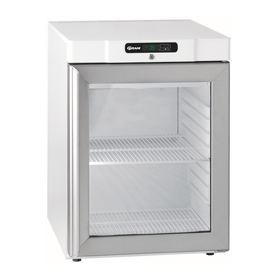
General description Condenser Main supply inlet Display Name plate Door Air intake Air distribution plate Shelves for storag Re-evapor t on tray Refrigerant / GWP value... -
Page 12: Electrical Connection
Electrical Connection Read the text below thoroughly before electrical connection. Connect the power cord found at the back of the cabinet to main supply inlet (see fig.6). The product is intended for connection to alternating current. The connection voltage (V) and frequency (Hz) are shown on the name plate in the cabinet (see Fig.6). -
Page 13: Starting Up
Starting up Display Connect the cabinet to main power To turn on the cabinet, push for 2 seconds The display shows the actual cabinet temperature, and indicates that power is connected. The cabinet is turned off likewise, by pushing for 2 seconds Control lights The following control lights are located at the display. - Page 14 Temperature alarm The controller is equipped with a temperature alarm, which constantly monitors the cabinet temperature. The lamp lights, if an alarm has occurred. The following alarms can be displayed. low temperature alarm high temperature alarm open door alarm Displaying alarm values: Push the button, and keep pushed for 1 second.
- Page 15 Push again, and the display flashes “- - - -” for 4 seconds. The alarms are now deleted, the LED is turned off, and the controller returns to temperature display. Error codes: If error Pr1 is displayed, it means that the temperature sensor is defect. Request service assistance.
- Page 16 It is recommended to clean the tray and water trap when necessary - at least once a year. Remember to disconnect the cabinet before cleaning. Be careful not to damage the re-evaporation pipe during cleaning.
-
Page 19: How To Replace Evaporator Fan Motor
How to replace Evaporator Fan Motor 1. Switch off the main switch and remove plug from socket 2. Unscrew the dew collector 3 screws as shown in fig 6. 3. Dew collector rested on inner box liner slot as shown in fig 7, remove it 4. -
Page 20: How To Replace Foil Heater
How to replace Foil Heater 1. Switch off the main switch and remove plug from socket. 2. Unscrew the dew collector 3 screws as shown in fig 6. 3. Dew collector rested on inner box liner slot as shown in fig 7, remove it. 4. -
Page 21: How To Replace Drip Tray
How to replace Drip Tray 1. Switch off the main switch and remove plug from socket. 2. Remove tray by pulling outside as shown in figure 10 3. Be careful not to damage the re-evaporation pipe during remove tray. 4. Replace new drip tray. Fig. -
Page 22: Reversing The Door
Reversing the door (Applicable to K and F models) The door can be changed from right hand hinged to left hand hinged, or vice versa. 1. Switch off the power at the mains socket. 2. Dismantle the four screws that hold the control panel (table top assembly) at front and back, pull the panel a little forward, and then tilt it upwards. - Page 23 Reversing the glass door (Applicable to KG and FG models) The door can be changed from right hand hinged to left hand hinged, or vice versa. 1. Switch off the power at the mains socket 2. Dismantle the four screws that hold the control panel (table top assembly) at front and back, pull the panel a little forward, and then tilt it upwards.
- Page 24 Fig. 13...
-
Page 25: How To Replace Condenser Coil
How to replace Condenser Coil 1. Switch off the power at the mains socket. 2. Remove screws of condenser coil as shown in figure 12 3. Remove brazing joint as shown in figure 14 4. Remove condenser and replace new condenser and refax vice versa. Brazing Joint Fig. -
Page 26: How To Replace Evaporator Coil
How to replace Evaporator Coil 1. Switch off the power at the mains socket. 2. Remove the dew collector as shown in figure 6 3. To remove evaporator, condenser has to be removed first and suction tubbing should be made straight, 4. -
Page 27: How To Replace Controller Board
How to replace Controller Board 1. Remove 2 screws of top cover as shown in figure 20 2. Open the panel as shown in figure 21. 3. Remove all connector from LAE controller as shown in Fig 22 4. Replace new LAE controller and refit the panel vice versa. Note: - There is no need to set program. -
Page 28: How To Replace Defrost Heater
How to replace Defrost Heater 1. Unscrew dew collector screw as shown in figure 23. 2. Remove defrost heater clip (7 Nos.) as shown in figure 24. 3. Remove wire connector (White). 4. Remove heater and replace new heater. 5. Reconnect wire connector and clips and refit the dew collector vice versa. Fig. -
Page 29: Controller Connections
Controller Connections Red Connector For Evaporator Fan Port Dark Red Connector Natural (White) Connector Fig 25 For Compressor Port For Power Port (Labelled “C”) (Labelled “P”) Blue Connector For Door Switch Port Sensor Probe Without Tape Identification For Room/Application Sensor Sensor Probe With Sticker For Defrost/Evaporator Sensor... -
Page 30: Evaporator Sensor Location
Evaporator Sensor Location The evaporator sensor is positioned as indicated by arrow in the below figure. Sensor Location Sticker Evaporator Sonsor Fig 27... -
Page 31: Air Duct Removal
Air Duct Removal 1. Switch off the power at the mains socket. 2. Remove the shelves. 3. Remove air duct by pressing the air duct mountings. Press on this surface to remove the air duct Press on this surface to remove the air duct Fig. -
Page 32: Electric Wiring Diagram
Wiring Diagram K220-K420... - Page 33 Wiring Diagram F220-F420...
- Page 34 Wiring Diagram KG220-KG420...
- Page 35 Wiring Diagram FG220-FG420...
-
Page 36: Piping Diagram
Piping Diagram...
Need help?
Do you have a question about the K220 and is the answer not in the manual?
Questions and answers