
Related Manuals for Hoshizaki HOSHIZAKI AMERICA 73183


Summary of Contents for Hoshizaki HOSHIZAKI AMERICA 73183
- Page 1 Hoshizaki America, Inc. “A Superior Degree of Reliability” www.hoshizaki.com Commercial Series Refrigerated Kitchen Equipment Models Reach-In B-Series SERVICE MANUAL Number: 73183 Issued: 3-23-2011 Revised: 10-4-2011...
- Page 2 Should the reader have any questions or concerns which have not been satisfactorily addressed, please call, send an e-mail message, or write to the Hoshizaki Technical Support Department for assistance. Phone: 1-800-233-1940; (770) 487-2331 Fax: 1-800-843-1056;...
-
Page 3: Table Of Contents
A. Refrigeration Circuit ... 21 B. Wiring Diagrams ... 22 IV. Service Diagnosis ... 29 A. Diagnostic Procedure ... 29 1. Refrigerator ... 30 2. Freezer ... 32 B. Control Module Check ... 35 C. Thermistor Check ... 36 D. Diagnostic Chart ... 37... - Page 4 V. Replacement of Components ... 39 A. Service for Refrigerant Lines ... 39 1. Refrigerant Recovery ... 39 2. Brazing ... 40 3. Evacuation and Recharge ... 40 B. Important Notes for Component Replacement ... 42 C. Door Reversal ... 42 VI.
-
Page 5: Important Safety Information
Important Safety Information Throughout this manual, notices appear to bring your attention to situations which could result in death, serious injury, or damage to the appliance or damage to property. WARNING Indicates a hazardous situation which could result in death or serious injury. - Page 6 • 208-230VAC: This appliance is equipped with a NEMA L14-20 four-prong locking, grounding plug to reduce the risk of potential shock hazards. It must be plugged into a properly grounded, independent 4-prong wall outlet. If the outlet is a 3-prong outlet or a 4-prong non-locking outlet, it is your personal responsibility to have a qualified electrician replace it with a properly grounded, independent 4-prong locking wall outlet.
-
Page 7: Specifications
I. Specifications A. Electrical and Refrigerant Data Model CR1B-FG/FS/HS CF1B-FS/HS CR2B-FG/FS/HS CF2B-FS/HS CR3B-FS/HS CF3B-FS/HS 208-230/115/60/1 See the nameplate for electrical and refrigerant data. The nameplate is located inside the cabinet. We reserve the right to make changes in specifications and design without prior notice. B. -
Page 8: Dimensions
2. Dimensions Exterior Exterior Model Width (W) Height (H) One Section 698.5 (27.5) Two Section 1397 (55) 1920.5 (75.61) Three Section 2108.2 (83) Door Door Opening Opening Height Model Width (DW) (DH) One Section 579 (22.8) Two Section 593.7 (23.37) 593.7 Three Section (23.37) -
Page 9: General Information
II. General Information A. Construction 1. One Section Compressor Control Box Control Module Power Cord Float Switch for Condensate Condensate Pump Pump Display Module Light Switch Reservoir (glass door Cover models only) Reservoir Thermostatic Expansion Valve Power Switch Condenser Fan Motor Condenser Light Door Switch... -
Page 10: Two Section
2. Two Section Compressor Control Box Control Module Float Switch Reservoir Cover Condensate Reservoir Pump Power Cord Display Module Light Switch (glass door models only) Door Switch Thermostatic Expansion Valve Condenser Fan Motor Condenser Power Switch Door Lock • Evaporator •... -
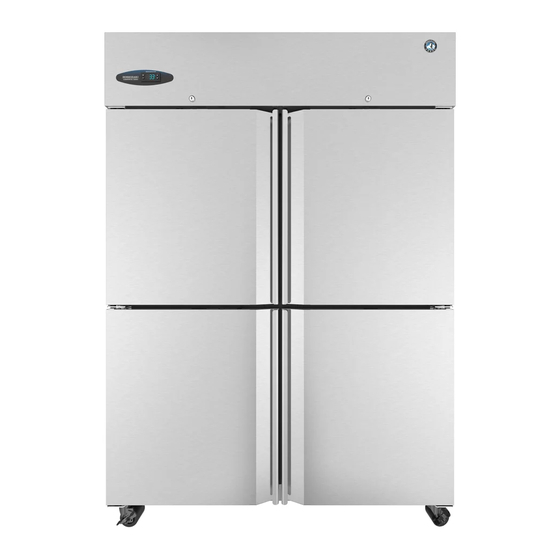
Page 11: Three Section
3. Three Section Thermostatic Expansion Valve Condenser Fan Motor Control Box Reservoir Cover Compressor Float Switch Control Module Reservoir Condensate Pump Power Cord CR3B-FS/HS Display Module Power Cord CF3B-FS/HS Receptacle Box Top Receptacles Have Power Lower Receptacles Do Not Condensate Pump Condenser Power Cords... -
Page 12: Sequence Of Operation
To silence the alarm, press and release the upper button. Alarm automatically resets when temperature drops to an acceptable range. a) Refrigerator 1. Startup/Cool Down EvapFM and MH energize. There is a slight delay before cabinet temperature appears on DM and Comp and ConFM energize. -
Page 13: B) Freezer
b) Freezer 1. Startup/Cool Down MH and PH energize. There is a slight delay before cabinet temperature appears on DM and Comp, ConFM, and EvapFM energize. 2. Cool Down Achieved CM monitors cooling of the cabinet via CTh. CTh cools to 3 EvapFM, MH, and PH continue. -
Page 14: Sequence Flow Charts
2. Sequence Flow Charts a) Refrigerator... -
Page 15: B) Freezer
b) Freezer... -
Page 16: Display Module
C. Display Module When the power switch is moved to the "ON" position there is a slight delay, then the current cabinet temperature is displayed. From the display module, the cabinet setpoint and temperature display scale can be changed. For further details, see "II.C.2. Controls and Adjustments."... -
Page 17: Controls And Adjustments
±3°F (±1.7°C) of the temperature setpoint. For example, for a refrigerator temperature setpoint of 36°F (2°C), the compressor comes on at 39°F (3.7°C), and the compressor goes off at 33°F (0.3°C). -
Page 18: Control Module
• The control module is fragile, handle very carefully. • Do not change wiring and connections. Never misconnect terminals. • Do not short out power supply to test for voltage. 1. Control Module Layout Refrigerator Control Module To Display Module Display Cable Defrost Thermistor... -
Page 19: Alarm Safeties
Low-Voltage Alarm (96VAC High-Temperature Alarm Note: When power is turned on, a high-temperature alarm can occur. Refrigerator: Cabinet temperature has exceeded the setpoint temperature by 10°F (5.6°C) for more than 2 hours. Freezer: Cabinet temperature has exceeded the setpoint temperature by 27°F (15°C) for more than 2 hours. -
Page 20: Compressor Protector, Short Cycle Protection, And High-Pressure Switch
Note: Time may vary with compressor protector or high-pressure switch activation. 3. High-Pressure Switch If pressure on the high-side of the appliance exceeds Hoshizaki specifications, the high-pressure switch activates and interrupts the compressor circuit, de-energizing the compressor until the pressure returns to an acceptable level. -
Page 21: Technical Data
III. Technical Data A. Refrigeration Circuit High-Pressure Switch Thermostatic Expansion Valve Defrost Heater and Defrost Thermostat (freezer only) Condenser Condenser Fan Drier Condensate Pan Low-Side Compressor Access Valve Evaporator Fans (2 or 3 depending on model) Condensate Pump Float Switch High-Side Access Valve Condensate Pump... -
Page 22: Wiring Diagrams
B. Wiring Diagrams 1. CR1B-FG * High-Pressure Switch Cut-out 270±10 PSIG Cut-in 190±20 PSIG... - Page 23 2. CR1B-FS/HS, CR3B-FS/HS * High-Pressure Switch Cut-out 270±10 PSIG Cut-in 190±20 PSIG...
- Page 24 3. CR2B-FG * High-Pressure Switch Cut-out 270±10 PSIG Cut-in 190±20 PSIG...
- Page 25 4. CR2B-FS/HS, CR3B-FS/HS * High-Pressure Switch Cut-out 270±10 PSIG Cut-in 190±20 PSIG...
- Page 26 5. CF1B-FS/HS, CF3B-FS/HS ** Defrost Thermostat * High-Pressure Switch Cut-out Cut-out 490±10 PSIG Cut-in Cut-in 370±20 PSIG A-5 (G) and later ° ° ° ° F±5 F (49 C±3 ° ° ° ° F±5 F (21 C±3...
- Page 27 6. CF2B-FS/HS, CF3B-FS/HS ** Defrost Thermostat * High-Pressure Switch Cut-out Cut-out 490±10 PSIG Cut-in Cut-in 370±20 PSIG A-5 (G) and later ° ° ° ° F±5 F (49 C±3 ° ° ° ° F±5 F (21 C±3...
- Page 28 7. CR3B-FS/HS Receptacle Box Connection Note: Only the top receptacles have power. 8. CF3B-FS/HS Receptacle Box Connection Note: Only the top receptacles have power.
-
Page 29: Service Diagnosis
5) Move the power switch to the "ON" position. 6) Confirm proper supply voltage (115VAC) to the power switch. On 3-section appliances, also confirm proper supply voltage to the receptacle box (115VAC for refrigerator/208-230VAC for freezer). Continue to "IV.A.1. Refrigerator" or "IV.A.2. Freezer." WARNING IMPORTANT... -
Page 30: Refrigerator
1. Refrigerator 7) Startup/Cool Down–EvapFM and MH energize. There is a slight delay, then Comp and ConFM energize and cabinet temperature turns on. a) Startup Diagnosis: Check that EvapFM energizes. If not, confirm that the door(s) are closed and DS contacts are closed. Check EvapFM blades for binding. Next, check for 115VAC at DSR terminals 7 and 8. - Page 31 8) Cool Down Achieved–CTh cools to 3°F (1.7°C) below setpoint. EvapFM and MH continue. Comp and ConFM de-energize. Diagnosis: If Comp and ConFM do not de- energize, confirm CTh status. See "IV.C. Thermistor Check." If CTh ohm reading is in range and Comp and ConFM do not de-energize, replace CM.
-
Page 32: Freezer
2. Freezer 7) Startup/Cool Down–MH and PH energize. There is a slight delay, then Comp, ConFM, and EvapFM energize and cabinet temperature appears on DM. Once DTh reaches 32°F (0°C), 4-hour Comp cumulative run timer starts. a) Startup Diagnosis: Check that EvapFM energize. If not, confirm that the door(s) are closed and DS contacts are closed. - Page 33 • The appliance should be a minimum of 4" (11 cm) from side walls. • A minimum of 10" (25 cm) overhead clearance should be provided for proper ventilation. 8) Cool Down Achieved–CTh cools to 3°F (1.7°C) below setpoint. EvapFM, MH, and PH continue.
- Page 34 3-minute Comp delay timer terminates: Have Comp and ConFM energized after DH is de-energized for 3 minutes? If not, check for 115VAC between CM C1 and CM N5. If 115VAC is not present, replace CM. If 115VAC is present between CM C1 and CM N5, check for 115VAC on CR coil (terminals 5 and 6).
-
Page 35: Control Module Check
N5. If "dEF" is displayed and 115VAC is not present, replace CM. 10) Check that the components restart after defrost termination. Refrigerator: Comp and ConFM energize as soon as the DTh termination temperature is satisfied. See "Defrost Termination" under "IV.A.1.9) Defrost" and "IV.C. Thermistor Check."... -
Page 36: Thermistor Check
In the event the cabinet thermistor reading is out of range (E1 alarm), the compressor operates on a fixed time basis of 5-minutes on and 5-minutes off. In the event the refrigerator defrost thermistor reading is out of range (E2 alarm), defrost initiation occurs every 4-hours of cumulative compressor run time and terminates on 20-minute minimum defrost timer. -
Page 37: Diagnostic Chart
D. Diagnostic Chart Before consulting the diagnostic charts, check the following: • Check the setpoint. For factory default settings, see "II.C.2.a) Default Settings." • Make sure the doors are not left open or opened too often and that they are sealing properly. - Page 38 Appliance Not Cooling - Possible Cause 11. Compressor Protector 12. Compressor 13. Condenser 14. Evaporator See "2. Evaporator is Frozen Up." 15. Refrigerant/Refrigerant Lines 2. Evaporator is Frozen Up Evaporator is Frozen Up - Possible Cause 1. Evaporator 2. Evaporator Fan 3.
-
Page 39: Replacement Of Components
V. Replacement of Components • This appliance should be diagnosed and repaired only by qualified service personnel to reduce the risk of death, electric shock, serious injury, or fire. • Move the power switch to the "OFF" position, then unplug the appliance from the electrical outlet before servicing. -
Page 40: Brazing
2. Brazing • R-134a and R-404A themselves are not flammable at atmospheric pressure and temperatures up to 176°F (80°C). • R-134a and R-404A themselves are not explosive or poisonous. However, when exposed to high temperatures (open flames), R-134a and R-404A can be decomposed to form hydrofluoric acid and carbonyl fluoride both of which are hazardous. - Page 41 5) Disconnect the gauge manifold hose from the vacuum pump and attach it to a refrigerant service cylinder. Remember to loosen the connection and purge the air from the hose. See the nameplate for the required refrigerant charge. Hoshizaki recommends only virgin refrigerant or reclaimed refrigerant which meets ARI Standard 700 (latest edition) be used.
-
Page 42: Important Notes For Component Replacement
To change the door swing, an HS kit from your local Hoshizaki distributor is required. See the table below. NOTICE! Improper installation of the HS kit may result in the doors not closing completely and/or the gaskets not sealing correctly. -
Page 43: Maintenance
• Before cleaning the appliance, move all foods into another clean refrigerator or freezer. • Do not splash water directly onto the appliance. This might cause short circuit, electric shock, corrosion, or failure. -
Page 44: Maintenance
"OFF" position before plugging in or unplugging the appliance to reduce the risk of electric shock. 1) Before shutting down the appliance, move the stored food into another refrigerator or freezer. 2) Reach over the front panel and move the power switch to the "OFF" position. The appliance will shut down. -
Page 45: Disposal
VII. Disposal When preparing the appliance for disposal, remove the door to reduce the risk of children getting trapped. Leave the shelves in place so that children may not easily climb inside. This appliance contains refrigerant and must be disposed of in accordance with applicable national, state, and local codes and regulations.
Need help?
Do you have a question about the HOSHIZAKI AMERICA 73183 and is the answer not in the manual?
Questions and answers