
Related Manuals for Fresenius Medical Care Agilia VP MC


Summary of Contents for Fresenius Medical Care Agilia VP MC
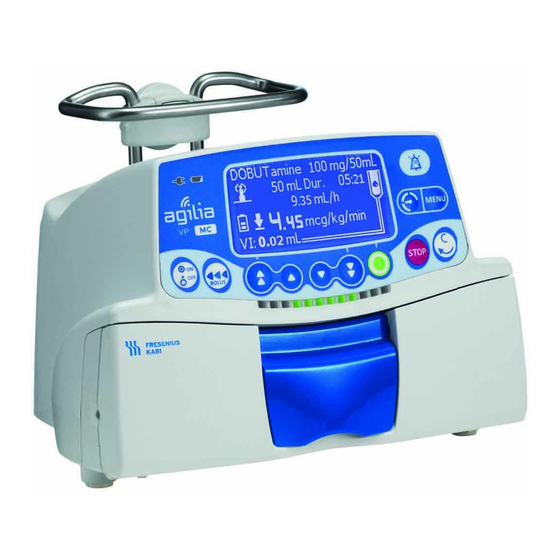
- Page 1 Agilia VP MC Agilia VP MC WiFi Volumetric Infusion Pumps Applicable to software version 2.2 Instructions For Use For Use in Healthcare Facilities and Homecare Environments...
-
Page 2: Symbol Descriptions
Symbol Descriptions Warning Name and address of the (Refer to the Instructions for Use) manufacturer / Date of manufacture Name and address of the Refer to the Instructions for Use manufacturing facility Protection against electric shock: Product reference / part number class II Non-ionizing electromagnetic Product serial number... -
Page 3: Table Of Contents
Table of Contents INTRODUCTION ....................9 COPE ..................9 NTENDED ..............9 RINCIPLES OF PERATION ............10 NTENDED RODUCTS TO BE NFUSED ..................11 NTENDED SERS ................11 NTENDED ATIENTS ................12 ONTRAINDICATIONS ................12 NVIRONMENT ........13 PECIFICITIES FOR OMECARE NVIRONMENTS AGILIA CONNECT INFUSION SYSTEM DESCRIPTION ..................16 RONT ) ........16 OTTOM EVICE... - Page 4 INSTALLATION ..............27 YPES OF NSTALLATIONS ............28 SING THE OTATING LAMP ) ..............29 TTACHING THE PUMP 5.3.1 Attaching to a Pole ................29 5.3.2 Attaching to a Rail ................30 5.3.3 Using on a Flat Table ................. 30 5.3.4 Attaching Two Pumps Together ............31 GETTING STARTED ..................32 LOWCHART...
- Page 5 7.10.1 Volume / Time / Rate (V/T/R) ............. 62 7.10.2 Volume / Rate (V/R) ................62 7.10.3 Volume / Time (V/T) ................62 7.10.4 Time / Rate (T/R)................62 7.10.5 Simple Rate (only with Drop Sensor) ..........63 7.10.6 Ramp-up / Ramp-down ..............63 7.10.7 Sequential Infusion................
- Page 6 8.24 ................98 IBRARY NFORMATION 8.25 .................99 LINICAL NFORMATION 8.26 ...................100 OPTIONS ..................101 OMMANDS ...............101 PTION ESCRIPTIONS .................102 ETTINGS 10 DATA COMMUNICATION 10.1 ..................103 VERVIEW 10.2 ...........103 OMMUNICATION VIA GILIA ABLES 10.3 ..............104 OMMUNICATION VIA 10.4 ................104 PLOAD 11 USER TEST 12 ALARMS AND SAFETY FEATURES 12.1 ..................106...
- Page 7 15.2 ..................124 15.3 (VTBI) ............125 OLUME NFUSED 15.4 (DTBI) .............125 NFUSED 15.5 ..................125 NFUSION 15.6 ................126 ONCENTRATION 15.7 ..................126 ATIENT 15.8 ...................126 ETECTION 15.9 ..............127 RESSURE ANAGEMENT 15.10 A ..................128 CCURACY 15.11 C ................130 ALCULATION ULES 15.12 U ............131 NITS AND ONVERSION ULES 16 CLEANING AND DISINFECTING...
- Page 8 20 TROUBLESHOOTING 21 RECYCLING 22 WARRANTY 22.1 ............151 ENERAL ARRANTY ONDITIONS 22.2 ................151 IMITED ARRANTY 22.3 ........151 ARRANTY ONDITIONS FOR CCESSORIES 23 GUIDANCE AND MANUFACTURER'S DECLARATION ON EMC 23.1 ..........152 LECTROMAGNETIC OMPATIBILITY 23.2 (ESD) ............152 LECTROSTATIC ISCHARGE 23.3 .153 LECTROMAGNETIC OMPATIBILITY AND NTERFERENCE UIDANCE...
-
Page 9: Introduction
Agilia VP MC can be used standalone or mounted on the Link Agilia rack. Agilia VP MC can be used for intermittent or continuous infusions. Agilia VP MC is intended for use on only one patient at a time. It can be reused indefinitely on multiple patients throughout its lifetime. -
Page 10: Intended Products To Be Infused
When using Agilia VP MC to infuse critical medications in healthcare facilities, ensure that adequate monitoring is provided, and that backup pumps and administration sets are available for immediate use. Only use Agilia VP MC for the infusion of fluids that are intended for infusion pumps. Administration Routes The system allows infusion via the following access routes: ... -
Page 11: Intended Users
It is recommended that users attend a refresher training session of about 20 minutes every year. For training, contact your Fresenius Kabi sales representative. Intended Patients Agilia VP MC is intended to be used according to healthcare facilities protocols on patients with the following characteristics: Patient Characteristics Male... -
Page 12: Contraindications
While the pump is infusing a patient, do not connect a computer installed with Agilia Partner software to perform technical operations. Use Environment Agilia VP MC is intended for use in the following environments: Healthcare facilities, under the supervision of trained healthcare personnel. -
Page 13: Specificities For Homecare Environments
Specificities for Homecare Environments Warning: Product version Only pumps with software version 2.2 or above can be used in homecare environments. In early versions, all homecare functionalities are unavailable. If your software version is not compatible with homecare environments, contact your Fresenius Kabi representative. Environment Considerations ... -
Page 14: Agilia Connect Infusion System
Agilia Connect Infusion System Agilia Range Description Volumetric Infusion Pump Pumps designed to deliver the contents of parenteral Agilia VP range infusion container (bag or bottle) through a line connected to a patient. Syringe Infusion Pump Agilia SP range Pumps designed to deliver the contents of a syringe through a line connected to a patient. - Page 15 Agilia Range Description Administration Sets Disposables Volumat Lines Administration sets can be in contact with the patient (applied part). Information For a list of compatible accessories, disposables and software, and for ordering information, refer to the System Components booklet.
-
Page 16: Description
Description Front View Figure 3.1: Front View Legend Handle Door Lever Pump Door Bottom View (Device Identification Label) For more information on device identification label symbols, see Symbol Descriptions, page 2. -
Page 17: Back View
Back View Figure 3.2: Back View Legend Release Button Power Cord Inlet Drop Sensor Connection Socket Infrared Cell Rotating Pole Clamp Attachment Lock Knob RS232 Communication Port Symbol Location Description Warning See section 18, page 110. Near Power Cord Inlet Warning See section 10, page 103. -
Page 18: Keypad
Keypad 3.4.1 Keypad Description Figure 3.3: Keypad Legend Screen Decrement 3 7 10 Battery Charge Status Indicator Fast Decrement 3 11 Power Supply Indicator Confirm Value / Move to Next Field 3 12 Wi-Fi Symbol Stop 3 13 On / Off Cancel Value / Move Back to Previous 3 14 Field... -
Page 19: Selection Keys
3.4.2 Keypad Details 3.4.2.1 Selection Keys Description Arrow Keys Keys for selecting volume, time, flow rate and other values. Fast Access to Maximum Value or Top of a List Fast Access to Minimum Value or Bottom of a List Note: ... -
Page 20: Display And Symbols
Display and Symbols 3.5.1 Infusion Status Symbol Description Infusion in Progress (All Profiles) This symbol shows a drop falling into the drip chamber. The drop appears in the drip chamber when an infusion is in progress. Infusion in Progress (Drop sensor connected) Infusion in Progress (Custom Profiles) This symbol is displayed when the pump is infusing a drug customized with Agilia Vigilant Drug’Lib software. -
Page 21: Navigation Buttons
3.5.3 Navigation Buttons Symbol Description start Start Confirm enter Access Function New ? Access Function and Clear Settings exit Exit Function Change Selection prog Program Function Select / Unselect See More Information Zoom in / Zoom out Move the Event Marker to the Left / Right 3.5.4 Alarms and Safety Features Symbol... -
Page 22: Data Communication
Symbol Description Data Set Loaded A new data set has been loaded to the pump. Packaging The Agilia VP MC packaging contains the following: 1 Agilia VP MC pump 1 Instructions for Use manual (this document + System Components booklet) ... -
Page 23: Fundamentals
Fundamentals Profiles A profile defines the device configuration and drug library used for a group of patients in a given health care environment. By default, factory settings include only 1 profile (Basic Profile). Custom profiles can be created and loaded to the pump with Agilia Vigilant Drug’Lib software. -
Page 24: Drug Libraries
Depending on the way it is pre-configured with Agilia Vigilant Drug’Lib software, a custom profile may or may not include all of the functionalities described in this IFU. Information We recommend using a custom profile when infusing critical drugs. ... -
Page 25: Drug X (Ml/H)
4.4.2 Drug X (mL/h) Drug X (mL/h) is an open entry that can be selected if the intended drug is not found in the drug library. It has the following characteristics: Fewer limits than the other drugs in the library. ... -
Page 26: Data Set
Data Set A data set is a combination of custom profiles (up to a maximum of 19) that can be uploaded to Agilia pumps with Agilia Vigilant Drug’Lib software. Device Device Device Device Device Configuration Configuration Configuration Configuration Configuration (factory) Drug Library Drug List Drug Library... -
Page 27: Installation
Installation Types of Installations A pump can be installed on any of the following: Location Comments See section 5.3.1, page 29. On a Pole Pole specifications: Diameter: from 15 to 40 mm See section 5.3.2, page 30. Rail specifications: On a Rail ... -
Page 28: Using The Rotating Pole Clamp
Location Comments Refer to the Agilia Holder Ambulance accompanying documents. In an Agilia Holder Ambulance Do not use accessories that appear to be damaged. For more information on accessories, refer to their respective accompanying documents. Warning The pump must be used in a horizontal and stable position to function properly. -
Page 29: Attaching The Pump(S)
5.2.2.1 Folding the Clamp Down (outward) You can fold the clamp down as follows: 1. Push the release button. 2. Fold the clamp outward. 5.2.2.2 Folding the Clamp Up (inward toward the pump) You can fold the clamp up as follows: 1. -
Page 30: Attaching To A Rail
5.3.2 Attaching to a Rail Only single pumps can be attached to a bed rail or gurney rail. 1. Rotate the pole clamp to the vertical position: see section 5.2.2.3, page 29. 2. Unscrew the clamp, attach to the rail, and screw the clamp until pump is fully secured to the rail. -
Page 31: Attaching Two Pumps Together
5.3.4 Attaching Two Pumps Together You can attach two pumps together either for transport, or before fixing them to a pole. 1. Fold both pumps’ pole clamps up: see section 5.2.2.2, page 29. 2. Slide the slot on the bottom of the upper pump onto the handle of the lower pump. -
Page 32: Getting Started
Getting Started Flowchart Once the pump is installed at the bedside, you must follow the steps below in order to install an administration set and power on the pump. Preparing the administration set and the fluid container Section 13.1, page 116. Priming the administration set Section 13.2, page 117. -
Page 33: Using The Pump For The First Time
Using the Pump for the First Time 1. Make sure the pump is correctly installed at the bedside. See section 5, page 27. 2. Plug the pump into the AC power supply. See section 17.1, page 137. 3. Before starting the pump for the first time, you must charge the battery for approximately 6 hours. -
Page 34: Reminder Message
Screen After Powering on Description The pump is operating on battery. The symbol shows three different charge levels: < 30 % battery charge 30 % - 70 % battery charge > 70 % battery charge No administration set is installed on the pump. ... -
Page 35: Installing The Administration Set In The Pump
Screen After Powering on Description Data Set information (optional) Installing the Administration Set in the Pump Warning Do not open the roller clamp until the OCS test has successfully completed. During all manipulations of the pump with administration set (administration set installation, door opening, administration set removal), close the roller clamp and make sure the line is closed. -
Page 36: Connecting A Drop Sensor
Connecting a Drop Sensor Using a drop sensor is recommended if the actual volume of the fluid container is not known accurately. The pump automatically detects the presence of a drop sensor. The presence of the drop sensor can be set as mandatory in the pump options. -
Page 37: Pump Height
Information When a drop sensor is detected on a pump, the following happens Simple Rate infusion mode is available and recommended, Programmable infusion ranges are different. Warning For transport during infusion, the pump with a drop sensor connected on it must be installed on a rolling stand. -
Page 38: Operation
Operation Flowchart Selecting a Profile Section 7.2, page 39. Custom Profile Custom Profile Basic Profile (with a Drug List) (with a Drug Library) Section 4.1.1, page 23. Section 4.1.2, page 23. Section 4.1.2, page 23. Selecting the Selecting the Infusion Rate Infusion Rate Section 7.3, page 40. -
Page 39: Selecting A Profile
Selecting a Profile You can only select a profile if more than one profile is loaded in the pump. 1. Press to power on the pump. 2. Press the arrow keys to select a profile that corresponds to the target group of patients. (lighthouse) symbol refers to custom profiles that contain drug libraries and have been configured with Agilia Vigilant Drug’Lib software. -
Page 40: Selecting The Infusion Rate (Flow Rate Or Dose)
Selecting the Infusion Rate (Flow rate or Dose) The programming mode step allows you to select the infusion rate. This step occurs just after selecting Basic Profile, or a custom profile with a drug list. Note: The infusion rates for each drug of a drug library are pre-defined with Agilia Vigilant Drug’Lib software. -
Page 41: Selecting A Drug
Selecting a Drug Note: The drug selection step is not applicable with Basic Profile. Drugs are sorted alphabetically by the first letter of their names: A C J L S U D ... -
Page 42: Programming An Infusion By Flow Rate
7.5.1 Programming an Infusion by Flow Rate 1. Press the arrow keys to program the Volume to be Infused (VTBI) and press OK. (Press to select the VTBI from pre-defined values: 0.1 mL, 10 mL, 20 mL, 50 mL, 100 mL, 250 mL, 500 mL, etc.) Information ... -
Page 43: Programming An Infusion By Dose
7.5.2 Programming an Infusion by Dose 7.5.2.1 Selecting the Drug Concentration Profile Drug Concentration Selection Procedure Basic Profile A- Basic Profile and Custom Profile (with a Drug List), page 43. Custom Profile (with a drug list) Custom Profile B- Custom Profiles, page 43. (with a drug library) A- Basic Profile and Custom Profile (with a Drug List) 1. -
Page 44: Select
Authorized Concentration Range Authorized Finite Concentrations Legend Unauthorized Range Hard Limits Authorized Range Default Value Finite Values Selecting the Drug Concentration Range Finite values 1. Press the arrow keys to select the concentration. 2. Press OK to confirm. 7.5.2.2 Selecting the Patient’s Characteristics Note: This step is only applicable with custom profiles that contain a drug library. - Page 45 7.5.2.3 Selecting the Infusion Unit Note: This step is only applicable with Basic Profile and custom profiles that contain a drug list. The infusion units for each drug of a drug library are pre-defined with Agilia Vigilant Drug’Lib software. 1. Press the arrow keys to select the infusion unit. 2.
-
Page 46: Select
3. Press the arrow keys to program the dose, and press OK. 4. Press OK to confirm the infusion settings, or C to cancel. 7.5.2.5 Programming a Loading Dose Note: This feature can be activated or deactivated in Agilia Vigilant Drug’Lib software (custom profiles). Information The loading dose is only available with the first start of an infusion. -
Page 47: Program
Programming a Loading Dose 1. Press the arrow keys to enter a value for the dose, and press OK to confirm. 2. Press the arrow keys to program the loading dose duration (__ h __ min __), and press OK to confirm each time segment. The VTBI and the flow rate are automatically calculated based on dose and duration settings. -
Page 48: Programming Beyond Soft Limits
7.5.3 Programming Beyond Soft Limits Note: This step is only available with custom profiles that contain a drug library. You can override soft limits, and adjust flow rate and dose within the authorized ranges. You cannot override a hard limit. Legend Unauthorized Range Hard Limits... -
Page 49: Starting An Infusion
Flow rate Dose During infusion, the upper or lower soft limit message will alternate with the drug name and concentration at the top of the screen. Starting an Infusion Flow rate Dose 1. Check the administration set integrity. 2. Check that no air remains in the administration set. 3. -
Page 50: Monitoring An Infusion
Monitoring an Infusion 7.7.1 Monitoring an Infusion when Programmed by Flow Rate Legend Custom Profile Sign When infusing a drug selected from the Agilia Vigilant Drug’Lib software library, this lighthouse sign is displayed on the screen continuously. VI (Volume Infused). Will increase during the infusion. - Page 51 7.7.2 Monitoring an Infusion when Programmed by Dose Legend Custom Profile Sign When infusing a drug selected from the Agilia Vigilant Drug’Lib software library, this lighthouse sign is displayed on the screen continuously. VI (Volume Infused). Will increase during the infusion. To clear VI, see section 8.7, page 81. Dose To change the dose during an infusion, see section 7.8.2, page 52.
-
Page 52: Functions During Infusion
Functions During Infusion 7.8.1 Stop Flow rate Dose To stop the infusion, press After 2 minutes, an alarm is generated as a reminder that the infusion is stopped. To restart the infusion, first confirm or modify the programming settings, then start the infusion. See section 7.5, page 41. 7.8.2 Rate Titration You can adjust the infusion rate (flow rate or dose) during the infusion. - Page 53 Information You can only add a secondary infusion when the primary infusion is programmed by flow rate. The secondary infusion drug must be programmed by flow rate. You can configure the end of secondary infusion settings in the pump options.
- Page 54 7.8.3.2 Accessing Secondary Infusion 1. Open the Primary / Secondary menu: Press Press the arrow keys to select 2. Press enter. 3. Press OK to confirm access to the secondary infusion. 7.8.3.3 Programming Secondary Infusion 1. Select a secondary drug (only when using a custom profile) and press OK.
- Page 55 4. Press the arrow keys to program the secondary flow rate and press OK. 5. Press OK to proceed. Information The current volume infused displayed becomes the secondary volume infused while infusing the secondary. Pri VI indicates the total primary volume infused since it was last cleared.
-
Page 56: Manual Return
7.8.3.5 End of Secondary Infusion Information The near end of infusion alert is not activated in secondary infusion. Manual Return to Primary Infusion 1. Press to silence the alarm. 2. Answer the question Continue sec ? Press Yes to program another secondary infusion. ... -
Page 57: Automatic Return
Automatic Return to Primary Infusion At the end of secondary infusion, a short beep is emitted. An alert message is displayed (optional). 1. Ensure that the primary line is open. 2. Press to acknowledge the message. The infusion automatically returns to the programmed primary infusion. -
Page 58: Administering A Bolus
7.8.4 Administering a Bolus A bolus is an extra dose that a pump can deliver during an infusion. There are two ways to deliver a bolus dose during an infusion: Direct bolus Programmed bolus Direct Bolus Programmed Bolus Access Key Occlusion Pressure Level Set to its maximum value: 750 mmHg / 100 kPa / 14.5 PSI... - Page 59 3. To administer a direct bolus, press and hold 4. Monitor the volume infused on the main display until the desired bolus is reached. 5. To stop the bolus, release the key. The infusion resumes its previous rate after the bolus is delivered. 7.8.4.2 Programmed Bolus Note: This feature can be activated or deactivated in Agilia Vigilant Drug’Lib software (custom profiles) or in the pump options...
-
Page 60: Completing An Infusion
The infusion resumes its previous rate after the bolus is delivered. Press exit or to exit the bolus function and save the programmed bolus settings. If you press again, this screen appears immediately and displays the settings of the last bolus. Interrupting a Programmed Bolus 1. -
Page 61: End Of Infusion
Silencing Near End of Infusion Alert Flow rate Dose 1. Press to silence the alarm. The infusion will continue until the VTBI reaches zero. 7.9.2 End of Infusion When the VTBI reaches zero, the infusion is complete. The following happens: ... -
Page 62: Powering Off
7.9.3 Powering off You can power off the pump as follows: 1. Press to stop the infusion. 2. Close the roller clamp. 3. Press and hold until the pump powers off. 7.10 Infusion Modes You can program an infusion with the different infusion modes available, depending on the pump configuration, and on the selected drug. -
Page 63: Simple Rate (Only With Drop Sensor)
7.10.5 Simple Rate (only with Drop Sensor) When a Drop Sensor is connected to the pump, Simple Rate infusion mode is available. 1. Press the arrow keys to select the flow rate. 2. Press OK. When no more drops are detected, the infusion is stopped and an alarm is generated. - Page 64 7. Press the arrow keys to program the ramp-down duration (__ h __), and press OK. 8. Press the arrow keys to program the plateau flow rate, and press OK. 9. Press OK to confirm, or C to cancel the settings. 10.Press start to start the infusion.
-
Page 65: 7.10.7 Sequential Infusion
2. If ramp-down is selected, check the ramp-down values and press OK. 7.10.7 Sequential Infusion You can program up to 20 infusion sequences with the sequential infusion mode, each with their own VTBI and flow rate. You can also program the following sequences: ... - Page 66 Sequence Programming Press the arrow keys to program the VTBI, and press OK. The infusion duration is automatically calculated. Press the arrow keys to program the flow rate, and press OK. VTBI The infusion duration is automatically readjusted. ...
-
Page 67: 7.10.8 Drops/Min
7.10.8 Drops/min You can program an infusion with the drops/min infusion mode as follows: 1. Select the drops/min infusion mode, see section 8.14, page 88. 2. Press OK to confirm the new infusion mode. 3. Press OK to confirm the drug. 4. -
Page 68: Other Functions
7.11 Other Functions 7.11.1 Priming the Administration Set Note: This feature can be activated or deactivated in Agilia Vigilant Drug’Lib software (custom profiles) or in the pump options (Basic profile). 1. Press to power on the pump. 2. Press 3. Make sure the administration set is not connected to the patient, as indicated on screen. -
Page 69: 7.11.2 Advancing An Air Bubble
7.11.2 Advancing an Air Bubble Note: This feature can be activated or deactivated in Agilia Vigilant Drug’Lib software (custom profiles) or in the pump options (Basic profile). When an air bubble is detected by the air detector (behind the pump door), an alarm is triggered. -
Page 70: 7.11.3 Auto-Restart
7.11.3 Auto-restart Auto-restart is an optional feature that alters the pump’s response when a downstream occlusion is detected. When this feature is activated, and when a downstream occlusion is detected, the following occurs: An alert is generated to inform the user that the pressure limit is reached. -
Page 71: 7.11.4 Pre-Programming The Pump
7.11.4 Pre-programming the Pump You can program the pump before installing the administration set. 1. Press to power on the pump. is displayed on top of the pump screen. Install set !!! 2. Make sure the pump door is closed. The prog symbol is displayed. -
Page 72: Menus
Menus Overview 8.1.1 Commands Operation Access menu or exit menu Select Confirm (corresponds to enter on the screen) Select / Deselect 8.1.2 Menu Description Stop Menu Symbol Infusion Associated Procedure Required Profile Displaying active profile information, page 74. ... - Page 73 Stop Menu Symbol Infusion Associated Procedure Required Ramp-up / Ramp-down Modifying a ramp-up /ramp-down infusion, page 89. Sequential Modifying a sequential infusion, page 89. Alarm volume Adjusting the alarm volume, page 90. Call-back Activating / Deactivating the call-back alert, page 91. ...
-
Page 74: Profile
Profile Symbol Procedure Displaying active profile information You can display the active profile name as follows: 1. Press 2. Press the arrow keys to select 3. Press enter. The active profile information is displayed. -
Page 75: Pressure
Pressure Symbol Procedure Modifying the pressure limit The pump pressure limit is pre-defined in the pump options in one of the following modes: 3 levels (low , medium , high The pressure limit is adjustable according to 3 pre-set values. ... - Page 76 3. Press the arrow keys to increase or decrease the pressure limit. 4. Press OK to validate. 5. Press to enable or disable the Auto-restart function (optional). 6. Press OK to confirm. 7. Press to enable or disable the DPS function (optional). 8.
-
Page 77: Volume T O B E Infused (Vtbi)
Volume To Be Infused (VTBI) Symbol VTBI Procedure Changing VTBI You can change the VTBI as follows: 1. Press VTBI 2. Press the arrow keys to select The active VTBI is displayed. 3. Press enter. 4. Press the arrow keys to modify the VTBI. 5. -
Page 78: Keypad Lock Status
Keypad Lock Status Symbol Procedure Locking / Unlocking the keypad You can use this feature to avoid inadvertent key presses. Note: The following features can be activated or deactivated in the pump options: Automatic lock: The keypad will lock automatically at infusion start, or after a time-out. - Page 79 Unlocking the Keypad You can unlock the keypad as follows: 1. Press 2. Press the arrow keys to select 3. Press enter. Unlock code enabled Unlock code disabled 4. Unlock the keypad as follows: If a code is required, press the keys to enter the unlock code. The keypad is unlocked.
-
Page 80: Battery Life
Battery Life Symbol Procedure Viewing the battery life You can view the battery life as follows: 1. Press 2. Press the arrow keys to select The time remaining under current flow rate conditions is displayed. The bar graph shows a visual representation of battery life. The symbol displayed shows the following: ... -
Page 81: Volume Infused / Dose Infused
Volume Infused / Dose Infused Symbol Procedure Viewing and clearing the volume or dose infused Flow rate Dose You can view and clear the volume or dose infused as follows: 1. Press 2. Press the arrow keys to select The total volume, or total dose, infused includes primary and secondary infusions, loading doses and boluses. -
Page 82: Pause
Pause Symbol Procedure Programming a pause You can program a pause as follows: 1. Press to stop the infusion. 2. Press 3. Press the arrow keys to select 4. Press enter. 5. Press the arrow keys to program the pause duration in hours and minutes, and press OK. -
Page 83: Drug
Drug Symbol Procedure Changing the drug selection You can change the drug selection as follows: 1. Press to stop the infusion. 2. Press 3. Press the arrow keys to select 4. Press enter. 5. Press OK to confirm. 6. Press the arrow keys to select the new drug. 7. -
Page 84: Patient
8.10 Patient Symbol Procedure Changing a patient’s weight or body surface area Information If the selected dose rate unit is weight-based (kg), the screen displays the patient’s weight. If the selected dose rate unit is body surface area-based (m²), the screen displays the patient’s body surface area. -
Page 85: Day/Night Mode
8.11 Day/Night Mode Symbol Procedure Switching between day mode and night mode This function switches between day mode and night mode The default night mode settings are as follows: The key-press beep is silenced. Infusion indicators and screen brightness are dimmed. Depending on your pump configuration, the switch between day and night mode may be managed either through this menu (manual mode), or according to pre-defined settings (auto mode). - Page 86 Switching from Night Mode to Day Mode You can switch to day mode as follows: 1. Press 2. Press the arrow keys to select 3. Press enter. 4. Press to activate day mode. The screen displays 5. Press OK to confirm.
-
Page 87: Primary / Secondary
8.12 Primary / Secondary Symbol Procedure Programming a secondary infusion To program a secondary infusion, see section 7.8.3, page 52. 8.13 Programmed Bolus Symbol Procedure Programming a bolus To program a bolus, see section 7.8.4.2, page 59. -
Page 88: Flow Rate (Ml/H) / Dose
8.14 Flow Rate (mL/h) / Dose mL/h Symbols Dose Procedure Changing the infusion mode Flow rate Dose You can change the infusion mode as follows: 1. Press mL/h Dose 2. Press the arrow keys to select 3. Press enter. The available infusion modes are displayed. Flow rate Dose 4. -
Page 89: Ramp-Up / Ramp-Down
8.15 Ramp-up / Ramp-down Symbol Procedure Modifying a ramp-up /ramp-down infusion Ramp-up/ramp-down infusion mode must be selected, see Section 8.14, Prerequisite page 88. To program an infusion in the ramp-up /ramp-down infusion mode, see section 7.10.6, page 63. 8.16 Sequential Infusion Symbol Procedure Modifying a sequential infusion... -
Page 90: Alarm Volume
8.17 Alarm Volume Symbol Procedure Adjusting the alarm volume You can adjust the alarm volume as follows: 1. Press 2. Press the arrow keys to select 3. Press enter. 4. Press the arrow keys to select the alarm volume. The pump emits an alarm at the selected volume level. 5. -
Page 91: Call-Back Alert
8.18 Call-back Alert Symbol Procedure Activating / Deactivating the call-back alert The call-back alert notifies the user when the set time interval has elapsed. Activating the Call-back Alert You can activate the call-back alert as follows: 1. Press 2. Press the arrow keys to select 3. - Page 92 Deactivating the Call-back Alert You can deactivate the call-back alert as follows: 1. Press 2. Press the arrow keys to select 3. Press enter. 4. To deactivate the programmed call-back alert, press the down arrow keys to set the duration period to "Off". 5.
-
Page 93: View Flow Rate History
8.19 View Flow Rate History Symbol Procedure Viewing flow rate history This function allows the user to check the current infusion’s history information in order to verify the dose administered. You can view flow rate history as follows: 1. Press 2. -
Page 94: View Pressure History
8.20 View Pressure History Symbol Procedure Viewing pressure history This function allows the user to check the current infusion’s history information in order to verify changes in pressure. You can view pressure history as follows: 1. Press 2. Press the arrow keys to select 3. -
Page 95: View Event Log
8.21 View Event Log Symbol Procedure Viewing the event log The event log displays details of the last events that occurred on the pump. Events are stored in the log even after the pump is powered off and on again. The log can store up to 1500 events. Older events are overwritten. -
Page 96: Date / Time
8.22 Date / Time Symbol Procedure Setting up the date and time You can set the date and time as follows: 1. Press 2. Press the arrow keys to select 3. Press enter. 4. Press the arrow keys to set the following: ... -
Page 97: Maintenance
8.23 Maintenance Symbol Procedure Displaying maintenance information You can display maintenance information as follows: 1. Press 2. Press the arrow keys to select 3. Press enter. 4. Press the arrow keys to scroll through the maintenance information. The following information is displayed: ... - Page 98 8.24 Library Information Symbol Procedure Displaying drug library information You can display drug library information as follows: 1. Press 2. Press the arrow keys to select The number of drugs contained in the drug library is displayed. 3. Press enter. All the drugs contained in the drug library are displayed.
- Page 99 8.25 Clinical Information Symbol Procedure Viewing remaining time before clinical information display If configured for the selected drug with Agilia Vigilant Drug’Lib, a protocol message will be displayed on the pump screen after a pre- defined period of time. You can view the remaining time before clinical information display as follows: 1.
- Page 100 8.26 Data Set Symbol Procedure Displaying active data set information You can display active data set information as follows: 1. Press 2. Press the arrow keys to select 3. Press enter. The active data set information is displayed.
-
Page 101: Description
Options Commands Operation Options access Option selection Confirm (corresponds to enter on the screen) Select / Deselect Selected current values are stored when the device is powered off after programming. To return to the normal menus, power off then power on again. Option Descriptions Four different option groups are available on the pump. -
Page 102: Unlock Code
Pump Settings The following options have different functions that you can select or deselect to customize your Agilia VP MC. Default Function Choice Pump Setting Selection assistance: display or hide selection [User 1]: assistance banner at the bottom of the screen... - Page 103 Data Communication 10.1 Overview Cable Communication Wi-Fi Communication Connection of 1 pump to a PC for the following Communication between a hospital information purposes: system server and a number of identified pumps Data set upload (via Agilia Vigilant Drug’Lib for the following purposes: ...
- Page 104 10.3 Communication via Wi-Fi The Wi-Fi option allows the pump to connect to a hospital information system without cables. To know if your pump is equipped with a Wi-Fi module, check for the presence of the Wi-Fi logo on the pump’s keypad. See section 3.4.1, page 18.
- Page 105 User Test The following protocol provides the user with a quick integrity check guide to ensure that the pump system is functional. Perform this user test before each use of the pump. 1. Check the external appearance of the pump for the absence of cracks or other visible damage.
- Page 106 Alarms and Safety Features 12.1 Introduction Agilia VP MC has a continuous monitoring system that begins when the pump is started. When an alarm is triggered, a message is displayed on the pump screen. We recommend that the user stand in front of the pump to read the message before acknowledgment.
- Page 107 12.3 General Remarks Alarms are not configurable. When two alarms occur at the same time, the higher priority alarm is displayed. When two alarms with the same priority level are triggered at the same time, the pump software assigns them a priority. ...
- Page 108 Stops Message Priority Problem / Resolution Infusion? The administration set is incorrectly positioned in front of the air sensor. Check the administration set installation in Set / air High (!!!) front of the air sensor and close the door. installation !!! Note: the key silences the alarm for 2...
- Page 109 12.4.3 Infusion Alarms Stops Message Priority Problem / Resolution Infusion? The VTBI is completed. Press to select new infusion settings High (!!!) End of infusion !!! (if required). Note: the key acknowledges the alarm. The secondary infusion is completed (only with manual return to primary).
- Page 110 Stops Message Priority Problem / Resolution Infusion? End of infusion - with KVO End of infusion ! The VTBI is completed and the KVO is activated according to its configuration in Agilia Vigilant Drug’Lib software or in the pump options. Low (!) Stop for new ...
- Page 111 Stops Message Priority Problem / Resolution Infusion? A downstream occlusion has been detected by the device. Check the line. Wait during pressure If the occlusion is released before the end High (!!!) measurement of temporization, the infusion will restart checking !!! automatically.
- Page 112 Stops Message Priority Problem / Resolution Infusion? Low battery. Connect the pump to a power supply. Medium (!!) Battery pre alarm !! Note: the key silences the alarm for 2 minutes. If the pump is not used during an extended Low (!) period, connect to a power supply and wait until the battery is charged.
- Page 113 12.4.8 Drop sensor Stops Message Priority Problem / Resolution Infusion? This message displays only if the drop sensor is mandatory. At start-up, the drop sensor is not connected to the pump. Connect drop High (!!!) sensor !!! Connect the drop sensor to the pump and the drip chamber.
- Page 114 Stops Message Priority Problem / Resolution Infusion? At start-up or when the infusion is stopped, a free flow is detected by the drop sensor. Close roller clamp. Uncontrolled Check the drop sensor and the High (!!!) flow !!! administration set installation.
- Page 115 Warning If the alarms persist when the pump is powered on again, do not use the device on a patient, and contact qualified biomedical engineering staff in your healthcare facility or your Fresenius Kabi sales representative. 12.5 Audio Only Information Signals Stops Type Comment...
- Page 116 Volumat Lines 13.1 Preparing the Administration Set and the Fluid Container Agilia Volumat Lines are supplied sterile and are indicated for single use. 1. Prepare the fluid container according to your healthcare facility’s protocol. 2. Select a Volumat Line. 3. Check the container, the line and access device integrity.
- Page 117 Precautions for the use of administration sets Use administration sets which have the smallest internal volume or “deadspace” to minimize residual volumes when administering medications or fluids at low infusion rates (e.g., less than 5mL per hour, and especially flow rates less than 0.5 mL per hour). This reduces the amount of time it takes for fluid to reach the patient, maintains delivery accuracy, and reduces occlusion detection times.
- Page 118 13.2.1 With a Bag The following diagram shows how to prime the administration set with a bag: 1. Remove the cap from the spike and insert the spike into the bag. 2. After hanging the bag, close the roller clamp. 3.
- Page 119 13.3 Other Uses of Administration Sets 13.3.1 Access Ports The administration set may be equipped with access ports, that can be used to connect a gravity line, a secondary line, or administer a manual bolus (needle-free port). Legend Upstream port (before the pump) Downstream port (after the pump)
- Page 120 13.3.2 Use of Administration Sets for Gravity Infusion 13.3.2.1 Gravity Infusion (without pump) In order to use the administration set to infuse the contents of the fluid container via gravity, without the pump, release the SafeClip as follows: 1. Close the roller clamp. 2.
- Page 121 Information Fresenius Kabi recommends the use of a back check valve or positive pressure infusion devices when an infusion on the pump is connected to a gravity line. This will prevent the back-up of IV fluid or medication into the gravity line. ...
-
Page 122: Storage
Device Storage 14.1 Precautions for Storage Handle the device with care during storage. Store the device in a cool, dry place. The storage area must be clean and organized. Clean and disinfect the device prior to storage. Warning If the device is not used for an extended period (longer than 2 months), it is recommended that the battery be removed from the device and put... - Page 123 14.4 Using the Device After Storage The device can be used immediately after storage without any cooling or warm up period. If the battery has been removed for long-term storage, contact your biomedical department in order to reinstall the battery prior to use. We recommend charging the battery for at least 6 hours.
-
Page 124: Flow Rate
Specifications Information The range of settings and default values described in this section correspond to the factory configuration. Range of settings and default values may be adjusted in the pump options (Basic Profile) or in Agilia Vigilant Drug’Lib software (custom profiles). Increment rules may be modified by Agilia Vigilant Drug’Lib software (custom profiles). -
Page 125: Volume To Be Infused (Vtbi)
15.3 Volume To Be Infused (VTBI) Default Minimum Format Range of Settings Value Increment (0.1 99.9) VTBI (Primary) 9999 (100 9999) (0.1 99.9) VTBI (Secondary) 9999* (100 9999) Direct Bolus (0.1 99.9) Programmed Bolus 1000 ... -
Page 126: Concentration
Default Minimum Format Range of Settings Value Increment Ramp (Total __ h __ 00h01 48h00** 12h00 00h01 Duration) Ramp (Ramp-up / __ h __ 00h00 06h00 00h01 00h01 Ramp-down) * If the calculated infusion time exceeds this value, ↑ 168h00 will be displayed on the pump. ** If the calculated infusion time exceeds this value, ↑... -
Page 127: Pressure Management
15.9 Pressure Management Information You can change the Basic Profile’s infusion pressure settings in the pump options. See section 9, page 101. You can pre-configure custom profiles’ infusion pressure settings with Agilia Vigilant Drug’Lib software. Setting Description Setting Format Default Value Mode Infusion pressure mode. -
Page 128: Accuracy
15.10 Accuracy Warning Accuracy (flow rate, time, volume infused, pressure) can be influenced by administration set model, administration set configuration, fluid viscosity, and fluid temperature. Note: All tests below are in accordance with the IEC 60601-2-24 standard and ANSI/AAMI ID26. 15.10.1Flow Rate Accuracy Accuracy Cumulative Flow Rate... - Page 129 15.10.4Volume Accuracy Accuracy < 10 mL: ± 0.5 mL Direct Bolus* > 10 mL: ± 5 % < 8 mL: ± 0.4 mL Programmed Bolus* > 8 mL: ± 5 % Limit to Detect Upstream ≤ 1.0 mL Occlusion* Bolus Volume at Occlusion Release Bolus Volume at Occlusion Rate 50 mmHg...
-
Page 130: Calculation Rules
15.11 Calculation Rules Infusion Stopped During Infusion Modify V, T is calculated according to T = V/R Modify R, Modify T, T is calculated according to T = V/R R is calculated according to R = V/T Modify V, ... -
Page 131: Units And Conversion Rules
15.12 Units and Conversion Rules 15.12.1Concentration Units Units Suffix nanog, microg, mg, g mmol Concentration mUnit, Unit /mL, /--mL Units cal, kcal 15.12.2Dose Units Units nanog/h, nanog/kg/min, nanog/kg/h microg/min, microg/h, microg/kg/min, microg/kg/h mg/min, mg/h, mg/24h, mg/kg/min, mg/kg/h, mg/kg/24h, mg/m²/h, mg/m²/24h g/h, g/kg/min, g/kg/h, g/kg/24h Dose Units mmol/h, mmol/kg/h, mmol/kg/24h... - Page 132 15.12.3Conversion Rules 1 micro unit = 1000 nano unit 1 m unit = 1000 micro unit 1 k unit = 1000 unit 1 unit/h = 24 unit/24 h 1 unit/min = 60 unit/h Conversion of a dose unit/kg/h (dose) × kg (weight) mL/h = including the unit/kg into unit/mL (concentration)
-
Page 133: Cleaning And Disinfecting
Cleaning and Disinfecting To avoid the risks of infection and microbial transmission, make sure to adequately clean and disinfect the equipment. Warning The disinfecting procedure must be done immediately after cleaning. Disinfecting the pump without prior cleaning is not effective. ... -
Page 134: Recommended And Prohibited Agents
16.2 Recommended and Prohibited Agents We recommend the following cleaning and disinfecting agents: 16.2.1 Recommended Agents Recommended Agent Didecyldimethylammonium chloride Cleaning (example: Wip’Anios Excel by Anios) Didecyldimethylammonium chloride Disinfecting (example: Wip’Anios Excel by Anios) 16.2.2 Prohibited Agents The following cleaning and disinfecting agents are prohibited: ... - Page 135 16.3.1 Cleaning Instructions Prerequisites The pump is powered off. The power cord and all other cables are unplugged. The air is at room temperature (20 to 25 °C). The operator is wearing suitable protective equipment. Protocol 1.
- Page 136 16.3.2 Disinfecting Instructions Prerequisites The cleaning protocol has been performed. The pump is powered off. The power cord and all other cables are unplugged. The air is at room temperature (20 to 25 °C). The operator is wearing suitable protective equipment. Protocol 1.
-
Page 137: Power Management
Power Management 17.1 AC Power Supply Precautions Check that the AC power supply voltage corresponds to the value indicated on the label on the bottom of the device. Do not exceed the permitted voltage. The power outlet must remain accessible at all times to allow emergency power supply disconnection. -
Page 138: Battery Operating Mode
Information Do not replace with a battery other than the one provided by Fresenius Kabi. Do not use the pump without the battery connected. Do not disconnect the battery when the device is operating on AC or battery power. -
Page 139: Technical Characteristics
Technical Characteristics 18.1 Power Supply It is mandatory to use an Agilia power cord compliant with the IEC 60227 standard. The power cord conductor must have a cross section of at least 0.75 mm 100 V - 240 V ~ / 50 / 60 Hz with functional Power supply earth AC Power... -
Page 140: Communication Port
18.4 Communication Port The connector located at the back of the device allows data communication with a PC. Serial Cable TTL output Power Input 10 V / 15 W to power supply the product Power Output 5 VDC / 150 mA to power Agilia USB cable 18.5 Infrared Communication The pump is equipped with an infrared cell located at the back of the... -
Page 141: Compliance
18.7.2 Alarms Sound Levels Sound Level (dBA) Alarm Priority High-priority Medium-priority Low-priority 18.8 Compliance Compliant with the following Index of protection against ElectroMedical standards: IP22 ingress of water or particulate Equipment Safety IEC 60601-1 matter IEC 60601-1-8 Compliant with the following Protection against leakage (ElectroMagnetic standard:... -
Page 142: Trumpet And Start-Up Curves
18.10 Trumpet and Start-up Curves The trumpet curve shows the variation of the mean flow rate accuracy over specific observation periods. The variations are presented only as maximum and minimum deviations from the overall mean flow within the observation window. Trumpet curves are presented below for a number of representative flow rates. - Page 143 18.10.1Flow Rate: 1 mL/h Legend Instantaneous flow rate Set flow rate Sampling time: 10 s Time (minutes) Figure 18.1: Start-up and instantaneous flow rate (1 mL/h over first 2 hours on 96 hours) Legend Measured variance from flow rate Error 25,1 Flow rate 12,9...
- Page 144 18.10.2Flow Rate: 25 mL/h Legend Instantaneous flow rate Set flow rate Sampling time: 10 s Time (minutes) Figure 18.4: Start-up and instantaneous flow rate (25 mL/h over first 2 hours on 96 hours) Legend Measured variance from flow rate Error Flow rate Sampling time: 10 s -2,5...
-
Page 145: Wi-Fi
Wi-Fi 19.1 General Information The Agilia Connect Infusion System includes an IEEE 802.11 radio- frequency transmitter incorporated in the Agilia Wi-Fi pumps. It operates using the following standards and frequencies: IEEE 802.11a: 5 GHz Frequency Band IEEE 802.11b: 2.4 GHz Frequency Band ... -
Page 146: Specifications
19.2 Specifications 19.2.1 Technical Specifications Description Technology IEEE 802.11 a/b/g/n 2.400 2.500 GHz (2.4 GHz is ISM band) Frequency Band 4.900 5.850 GHz (High Band) OFDM with BPSK, QPSK, 16-QAM, and 64-QAM 802.11b with CCK and Modulation DSSS Wireless Security... - Page 147 19.2.3 Protocols and Standards This wireless functionality references and uses the following protocols and standards: IEEE 802.11a/b/g/n standard WPA/WPA2-Entreprise, WPA/WPA2-PSK (Wi-Fi protected access) is a long-term security solution for wireless networks. For more information, refer to the IEEE 802.11. ...
- Page 148 Troubleshooting Issue Recommended Actions The pump is unstable when mounted. Check that the rotating pole clamp is fastened. The pump is damaged, or you notice Remove the power cord. something abnormal (unusual noise, Contact your biomedical department or your abnormal heat or smoke).
- Page 149 Issue Recommended Actions Connect the pump to the AC power supply. Then, wait few minutes without touching the keypad until the message At start-up, the pump displays: disappears and the pump starts as usual. "Software is upgrading...". Contact your biomedical department, or your Fresenius Kabi sales representative.
-
Page 150: Recycling
Recycling Before disposal, remove the battery from the device. Batteries and devices with this label must not be disposed of with the general waste. They must be collected separately and disposed of according to local regulations. Information For more information on waste processing regulations, contact your Fresenius Kabi sales representative or the local distributor. - Page 151 Warranty 22.1 General Warranty Conditions Fresenius Kabi guarantees that this product is free from defects in material and workmanship during the period defined by the accepted sales conditions, except for the batteries and the accessories. 22.2 Limited Warranty To benefit from the materials and workmanship guarantee from our Fresenius Kabi sales representative or authorized agent, make sure to observe the following conditions: ...
- Page 152 Guidance and Manufacturer's Declaration on 23.1 Electromagnetic Compatibility Warning The Agilia pump and its accessories are intended to be used in the electromagnetic environments specified below. The customer or the user of the Agilia pump should ensure that it is used in such environments.
- Page 153 The following environmental conditions related to electrostatic sensitive components (ESD standards) must be observed: Floors coated with wood, tiles or concrete Relative humidity of at least 30% If it is not possible to guarantee this environment, the following additional precautions must be taken: ...
- Page 154 Warning Use of the Agilia pump adjacent to or stacked with other equipment should be avoided because it could result in improper operation. If such use is necessary, this equipment and the other equipment should be observed to verify that they are operating normally. ...
- Page 155 23.4 EMC and essential performances In the case of electromagnetic disturbances, if the essential performance, Section 15.1, page 124, is lost or degraded, the consequences for the patient are as follows: overdose, underdose, delay of therapy, air embolism, trauma, exsanguination. 23.4.1 Table 1 - Guidance and Manufacturer's Declaration - Electromagnetic Emissions...
- Page 156 IEC 60601-1-2 - - - - - - - - - - - - - - Compliance Level Electromagnetic Environment - IEC 60601-2-24 Immunity Test Obtained by Guidance and ANSI/AAMI the Device ID26 Test Level Electrostatic ± 6 kV contact ±...
- Page 157 23.4.3 Table 4 - Guidance and Manufacturer's Declaration - Electromagnetic Immunity Warning The Agilia pump and its accessories are intended to be used in the electromagnetic environments specified below. The customer or the user of the Agilia pump should ensure that it is used in such environments.
- Page 158 23.4.4 Table 6 - Recommended Separation Distances Between Portable and Mobile RF Communication Equipment and the Agilia Pump Information The Agilia pump and its accessories are intended for use in electromagnetic environments in which radiated RF disturbances are controlled. ...
- Page 159 EMC test deviations and suplementary tests 23.4.5 To ensure compatibility with the new EMC standard IEC / EN 60601-1-2 Ed4 and special environments, specific, additional or deviating tests are listed below with respect to the basic tests, in accordance to manufacturer risk analysis. IEC 60601-1-2 Compliance level Electromagnetic...
- Page 160 IEC 60601-1-2 Compliance level Electromagnetic Immunity test IEC 60601-2-24 obtained environment – guidance Test level by the device Electrical Fast ± 2 kV for power ± 2 kV for power Electricity power quality should be that transient / Burst supply lines supply lines of a typical domestic, commercial or IEC 61000-4-4...
-
Page 161: Maintenance
Servicing 24.1 Information on Device Servicing If the device must be sent for servicing, proceed as follows: 1. Contact Fresenius Kabi to have packaging shipped to your facility. 2. Clean and disinfect the device. 3. Pack the device in the provided packaging. 4. - Page 162 24.3 Quality Control Upon request by the healthcare facility, a quality control check can be performed on the device every 12 months. A regular quality control check (not included in the guarantee) consists of various inspection operations listed in the technical manual. Information ...
- Page 163 Glossary of Terms Term Description Amperes Alternating Current Ampere-hours AIDC Automatic Identification and Data Capture Amplitude Modulation Amperes per meter BPSK Binary Phase Shift Keying Body Surface Area Calorie Complementary Code Keying Centers for Disease Control CISPR Special International Committee on Radio Interference CT Scan Computed Tomography Decibels...
- Page 164 Term Description Electrocardiogram ECMO ExtraCorporeal Membrane Oxygenation Electroencephalogram Electromagnetic compatibility ErXX Error message Electrostatic Discharge Federal Communications Commission Frequency Modulation Feet General Public License GTIN Global Trade Item Number H/W/D Height / Width / Depth High Frequency Hectopascals HTTP HyperText Transfer Protocol Hertz Industry Canada International Electrotechnical Commission...
- Page 165 Term Description Milliamperes Milliequivalents mL/h Milliliters per hour mmHg Millimeters of Mercury mmol Millimole Metal Oxyde Semiconductor Magnetic Resonance Imaging mW/sr Milliwatts per steradian Not Applicable Nuclear Magnetic Resonance Occlusivity Check System OFDM Orthogonal Frequency Division Multiplexing Operating Room Personal Computer Pounds per Square Inch Phase Shift Keying Quadrature Amplitude Modulation...
- Page 166 Term Description Universal Serial Bus Test specification level Volts Volt-Amperes Volts Direct Current Volume Infused Vrms Root Mean Square Voltage VTBI Volume to Be Infused Volts per meter Watts Wi-Fi Protected Access...
- Page 167 Appendix: Factory Configuration Feature Availability Feature Availability Profile V/T/R Pressure management Volume to be infused Keypad lock Infusion status Modes Ramp-up / Battery life Ramp-down Volume Infused Sequential / Dose infused Pause ...
- Page 168 Index Drop Sensor 36, 63 Drops/min 25, 67 Administration Set Drug 24 Change 121 Change 83 Install 35 Concentration Selection 43 Other Uses 119 Select 41 Prepare 116 Drug Library 24 Prime 68, 117 Display Information 98 Remove 121 Drug X (mL/h) 25 Replacement Interval 121 Agilia Connect Infusion System 14 Agilia USB Cable 104...
- Page 169 Pressure DPS 76 Keypad Management 127 Description 18 Modify Limit 75 Lock / Unlock 78 Operating Range 12 Unlock Code 102 Priming KVO 61, 65 Manual Prime 117 Prime With Pump 68 Profile 23 Language Selection 102 Basic Profile 23 Loading Dose Custom Profile 23 Pause 47...
- Page 170 Training 11 Troubleshooting 148 Trumpet Curves 142 Units 131 User Test 105 Users 11 V/R 25, 62 V/T 25, 62 V/T/R 25, 41, 62 Volume Infused 81 VTBI 77, 125 Warranty 151 Wi-Fi 20, 102, 104 Communication 145 Specifications 146...
- Page 171 Made in France Revision date: March 2020 Fresenius Kabi AG Fresenius Vial S.A.S 61346 Bad Homburg Le Grand Chemin Germany 38590 Brézins France www.fresenius-kabi.com 0 1 2 3 First CE Mark: Agilia VP MC WiFi: December 2015 Agilia VP MC: November 2016...
-
Page 172: Software Version
Local Contacts for Servicing Fresenius Kabi AG Fresenius Vial S.A.S 61346 Bad Homburg Le Grand Chemin Germany 38590 Brézins - France...
Need help?
Do you have a question about the Agilia VP MC and is the answer not in the manual?
Questions and answers