
Related Manuals for Fresenius Medical Care 2008k2


Summary of Contents for Fresenius Medical Care 2008k2
- Page 1 2008K HEMODIALYSIS SYSTEM PREVENTIVE MAINTENANCE PROCEDURES Part Number 508138 Rev. J...
- Page 2 FRESENIUS MEDICAL CARE NORTH AMERICA 800-227-2572 Fresenius Medical Care North America 920 Winter St. Waltham, MA 02451 Manufactured by: Fresenius USA, Inc. 4040 Nelson Avenue Concord, CA 94520 Page ii 2008K Preventive Maintenance Procedures P/N 508138 Rev. J...
- Page 3 PREVENTIVE MAINTENANCE PROCEDURES Part Number 508138 Rev. J INCLUDING PREVENTIVE MAINTENANCE CHECKLISTS SIX (6) MONTH AND ANNUAL/4000 HOUR http://www.fmcna.com Copyright 2008 - 2017 Fresenius Medical Care, All Rights Reserved Page iii 2008K Preventive Maintenance Procedures P/N 508138 Rev. J...
- Page 4 This document contains proprietary information of Fresenius USA, Inc. d/b/a Fresenius Medical Care North America and its affiliates (“Fresenius Medical Care”). The contents of this document may not be disclosed to third parties, copied, or duplicated in any form, in whole or in part, without the prior written permission of Fresenius Medical Care.
-
Page 5: Table Of Contents
PREVENTIVE MAINTENANCE PROCEDURES TABLE OF CONTENTS 1.0 INTRODUCTION ..........................1 TEST EQUIPMENT AND SUPPLIES NEEDED ................1 OPERATING MODES ........................ 3 FRONT PANEL CONTROLS ...................... 4 MEASURING FLUID VOLUMES ....................7 2.0 SIX (6) MONTH PREVENTIVE MAINTENANCE ................8 FILTERS ........................... 10 PRE-UF PUMP FILTER ...................... - Page 6 Failure to do so may result in electrical shock to the operator or patient Warning! Only Original Equipment Manufacturer (OEM) Fresenius Medical Care parts should be used in the repair or upgrade of the Fresenius Medical Care 2008K Hemodialysis System.
-
Page 7: Introduction
INTRODUCTION Preventive Maintenance for the 2008K Hemodialysis System is simple and straightforward. Maintenance is performed in only two intervals: six (6) months, and annually or after 4000 hours of operation. The maintenance procedures have been devised to require a minimum of time while ensuring that the machine is maintained in optimum operating condition. - Page 8 • 2008K Calibrations Procedures (part number 508137). • Test Kit (part number 150034), which contains two pressure gauges with fittings and hoses for measuring loading pressure and deaeration pressure. • Dialysate meter to measure dialysate pressure, temperature and conductivity at the ends of the dialysate lines.
-
Page 9: Operating Modes
OPERATING MODES The following preventive maintenance procedures contain instructions to place the 2008K into Dialysis Mode and Service Mode. To place the machine in Service Mode, turn the machine power On and wait for the message, Press CONFIRM for Service Mode to appear. Once it appears, press the [CONFIRM] key and the message will change to Machine in Service Mode. -
Page 10: Front Panel Controls
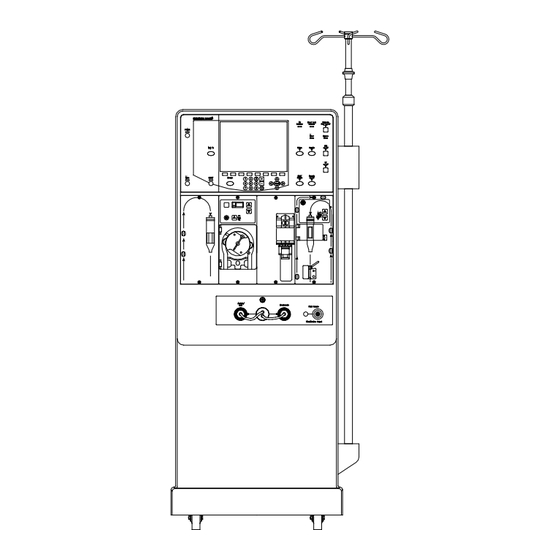
FRONT PANEL CONTROLS The front panel consists of many areas. The following illustrates these areas: LCD Screen Control Panel Screen Keys Data Entry Keys Navigation Keys Control Panel Figure 1 - 2008K Front Panel Control Panel Operation Throughout the preventive maintenance procedures, whenever a control panel key is to be pressed, the appropriate key name is surrounded by square brackets as in the following example: Press the [CONFIRM] key and the screen will change. - Page 11 Screen Operation The screen is designed to display information and is used to enter data. The following describes the type of buttons and data boxes that will be encountered during the calibration process. Data Button A yellow data button is used during calibration to enter a measured volume or value.
- Page 12 Screen Button (menu selection) Some screen buttons will display a menu of choices. To display the menu, use the ▲ ▼ ◄ ► navigation keys ([ and [ ]) to highlight the screen button and press the [CONFIRM] key. The menu will be displayed with the current selection highlighted. ▬...
-
Page 13: Measuring Fluid Volumes
MEASURING FLUID VOLUMES Several of the following procedures require measuring fluid volumes using graduated cylinders and laboratory burets. When making these measurements do the following: • Make certain the container is clean and dry before collecting the fluid to be measured. -
Page 14: Six (6) Month Preventive Maintenance
SIX (6) MONTH PREVENTIVE MAINTENANCE Perform the following Preventive Maintenance procedures every six (6) months of machine operation. Make copies of the Six (6) Month Preventive Maintenance Checklist provided in the back of this manual and use them to record the maintenance done. Note: When performing an Annual Preventive Maintenance do not perform the six (6) month procedures below first. - Page 15 9-VOLT BATTERY BLOOD PRESSURE MODULE DIALYSATE LINE CONN. O-RINGS P/N 579097 STRAIN RELIEF DIALYSATE INLINE FILTER HEATER P/N 650113 CONNECTIONS INLET WATER FILTER P/N 330636 REDUNDANT GROUND UF PUMP DRAIN PORT ADJUSTMENT BICARBONATE PUMP HEATER ELEMENT INLET PRESSURE P/N 250169 REGULATOR ACID PUMP BEHIND INLET PRESSURE...
-
Page 16: Filters
FILTERS Clean filters as follows. Replace any filters that appear damaged or corroded. 1. Inlet Water Filter in the inlet connector of the water supply (See Figure 3, pg. 9). Warning! After cleaning or replacing the inlet filter screen, disinfect the water inlet line as described in the Operator’s manual and in accordance with your Unit Policy. -
Page 17: Uf Pump Check Valves
UF PUMP CHECK VALVES Caution: If a check valve is replaced, ensure it is oriented correctly to allow fluid flow in the proper direction. Inspect the UF pump Output check valves (one at the UF pump output and the other downstream at the UF Sample Port). -
Page 18: Uf Pump
Shock Hazard: Do not operate the machine if the resistance is greater than 0.2 ohm. A shock hazard to operators and patients could exist. 7. With a digital multimeter, measure the resistance between the round (ground) pin on the power plug and the redundant ground terminal on the machine (See Figure 3, pg. -
Page 19: Temperature
TEMPERATURE Verify that the actual dialysate temperature measured by an external temperature meter agrees with the display screen within 0.3°C at 37°C and 39°C as follows: 1. Connect the dialysate lines to an external temperature meter. 2. Place the machine in Dialysis Mode with concentrate in the system. Clear any alarms. -
Page 20: Alarm Operation And Pressure Holding Tests
ALARM OPERATION AND PRESSURE HOLDING TESTS Verify the automatic alarms produce the responses shown in Table 1 and the machine passes the automatic pressure holding test as follows: 1. Place the dialysate lines in the shunt and close the door. Warning! The use of a “test drip chamber”... - Page 21 Table 1. Alarm Tests. ALARM TEST RESPONSE Red visual alarm Air Detector Venous clamp closes Blood pump stops Red visual alarm Blood Leak Venous clamp closes Blood pump stops Red visual alarm Arterial Pressure Venous clamp closes Blood pump stops Red visual alarm Venous Pressure Venous clamp closes...
-
Page 22: Verify Ph
6. When the tests shown in Table 1 are complete, the machine conducts a pressure holding test. When the test ends verify that the display screen reports TEST COMPLETE, indicating that all the tests were passed successfully. Press the [RESET] key. 7. -
Page 23: Final Checks
2.11 FINAL CHECKS Before returning the machine to clinical use after successful completion of all of the Preventive Maintenance procedures listed above, complete the following: • Verify that the machine label with serial number is in place, usually on the back of the cabinet near the Monitor Control Unit or above the quick connectors of the open shunt door assembly. -
Page 24: Annual (4000 Hour) Preventive Maintenance
ANNUAL (4000 HOUR) PREVENTIVE MAINTENANCE Perform the following Preventive Maintenance procedures every 12 months or 4000 hours of machine operation, whichever comes first. Perform the procedures in the order given below to complete the Annual Preventive Maintenance. Make copies of the Annual Preventive Maintenance Checklist provided at the back of this manual and use them to record the maintenance done. -
Page 25: Pre-Uf Pump Filter
PRE-UF PUMP FILTER Replace the Pre-UF Pump Filter (part number 672574). Caution: Do not attempt to disassemble the Pre-UF Pump Filter. If not properly reassembled, the Pre-UF Pump filter may leak. A leak in the hydraulic system at this location may affect the operation of the machine or cause fluid loss from the patient. -
Page 26: Heater Element
HEATER ELEMENT Shock Hazard: Dangerous high voltage is present at these connections when the machine is operating. Ensure the machine is disconnected from the wall outlet. Caution: The heater element is hot enough to inflict serious injury if it is touched while power is applied or shortly after power is removed. -
Page 27: Deaeration Motor Brushes
DEAERATION MOTOR BRUSHES Replace the deaeration motor brushes every 8000 hours using the following steps: 1. Remove the complete deaeration motor/pump assembly from the machine. 2. Using a marker, make marks on the motor housing and motor cap as illustrated below. These marks will ensure the correct alignment when reassembling the motor case. -
Page 28: Inlet Water Pressure Regulator
INLET WATER PRESSURE REGULATOR Verify that the regulator provides the proper water pressure as follows: 1. Shut off the water supply to the machine. 2. Install a pressure gauge with a T-fitting to monitor the pressure at the outlet side of the Inlet Pressure Regulator (See Figure 3, pg. 9). Caution: Use tie wraps or tubing clamps to secure the connections. -
Page 29: Online Clearance Test (If Applicable)
ONLINE CLEARANCE TEST (IF APPLICABLE) If the machine is equipped with Online Clearance (OLC), conduct the following test: OLC Self-Test With stable temperature and conductivity, start an OLC Self-Test by selecting the OLC Self-Test screen button on the Kt/V screen. ▬... - Page 30 ▬ 4. Switch to the debug screens by pressing and holding the [ ] and [ ] data entry keys at the same time for approximately 1 sec. The main display will change indicating that the machine is in debug mode. ▬...
- Page 31 15. On debug screen #5, locate TPOS and observe its value for 1 minute. During this time record the highest and lowest values observed in the table below. Highest Value Lowest Value Difference TPOS 16. Calculate the difference between the highest and lowest TPOS value and record it in the table above.
-
Page 32: Deaeration And Loading Pressure
3.10 DEAERATION AND LOADING PRESSURE Verify that the deaeration pressure is between –24 and -25 inHg and the loading pressure is between 18 and 20psi (between 23 and 25psi if a DIASAFE Plus filter system is installed) as follows: 1. -
Page 33: Flow Relief Pressure
3.11 FLOW RELIEF PRESSURE Verify that the flow relief pressure is between 29 and 30psi (between 35 and 36psi if a DIASAFE Plus filter system is installed) as follows: 1. Turn the machine on in Service mode. From the Calibrate Hydraulics the Flow Pressure screen button. -
Page 34: Concentrate And Bicarb Pumps
3.12 CONCENTRATE AND BICARB PUMPS Test the Concentrate and Bicarbonate diaphragm pumps as described in Section 4.3. 3.13 UF PUMP Calibrate the UF Pump Volume (Refer to the 2008K Calibration Procedures – part number 508137.). Record the measured value on the Annual/4000 Hour Preventive Maintenance Checklist. -
Page 35: Blood Leak And Dimness
3.17 BLOOD LEAK AND DIMNESS Verify that the blood leak level is between 4.5 and 5.2 volts and the blood dimness level is within 5.0 ±1.0 volts as follows: ▬ 1. Switch to the debug screens by pressing and holding the [ ] and [ ] data ... -
Page 36: Arterial, Venous And Transmembrane Pressure
3.18 ARTERIAL, VENOUS AND TRANSMEMBRANE PRESSURE ARTERIAL PRESSURE 1. Inspect the internal pressure transducer protector for contamination. If contamination is found, replace the pressure transducer protector (part number M30971) and remove and disinfect the pressure port with 1:100 bleach for a minimum of 15 minutes. 2. - Page 37 VENOUS PRESSURE 1. Inspect the internal pressure transducer protector for contamination. If contamination is found, replace the pressure transducer protector (part number 650158) and remove and disinfect the pressure port with 1:100 bleach for a minimum of 15 minutes. 2. Open the venous transducer port P On the level detector module to air (atmospheric pressure).
- Page 38 TRANSMEMBRANE PRESSURE With dialysate flow ON, ensure the dialysate lines are full of fluid and no air is visible passing through the flow indicator. Hang a four-way connector to the I.V. pole at normal dialyzer height. Set dialysate flow to 500ml/min, then press the [CONFIRM] key. Open the arterial (P ) and venous (P ) transducer ports to air...
-
Page 39: Dialysate Flow
3.19 DIALYSATE FLOW Verify the dialysate flow is within ±3% of the stated rate at 500ml/min as follows: Note: All flow rates are controlled by the software. Testing the rate at 500ml/min verifies the accuracy of all rates. 1. In Dialysis Mode, turn the dialysate flow ON at 500ml/min. Verify that the UF pump is OFF and the machine is out of bypass. - Page 40 7. Extend the syringe plunger past the 10ml mark. Install the syringe into the pump and latch the plunger handle into the carriage. If needed, squeeze the carriage/plunger release lever to slide the carriage up to meet the plunger handle. The syringe plunger should be at a position greater than 10ml. SYRINGE BODY HOLDER CARRIAGE BAR PLUNGER HOLDER...
- Page 41 12. When the pump stops, use the table below to verify the time to run a 5ml Bolus is correct for the selected syringe type. Type Syringe Size 5ml Bolus Time B-D Black 10ml 29.4 – 30.4 seconds Terumo 10ml (12ml) 24.5 –...
-
Page 42: Blood Pump
3.21 BLOOD PUMP Clean and test the arterial blood pump module as follows: 1. Remove the blood pump rotor by opening the door, pulling out the handle and turning the rotor 90 degrees 2. Clean the rollers with a cloth dampened only with water. 3. - Page 43 12. Close the blood pump door and press the [RESET] key to clear the alarm. 13. Test the pump as follows: • Set the Tubing Size to 8mm. • Insert a bloodline in the pump. Do not change the setting of the tubing size selector, even if you are not using 8mm tubing.
-
Page 44: Level Detector
3.22 LEVEL DETECTOR Caution: In the following steps, the level detector must be removed from the machine cabinet. Before returning it to the cabinet, wipe the lower edge of the module and the level detector cabinet opening to remove any residual disinfecting agent. - Page 45 3. Connect a syringe and a pressure gauge to the venous line above the occlusion clamp. 4. With the syringe, apply a pressure of at least 30psi (1550mmHg) to the venous line while watching the end of the venous line in the water. 5.
-
Page 46: Alarm Operation And Pressure Holding Tests
RELAY CONTACT TEST A relay prevents the level up and level down membrane keys on the face of the level detector to function if they are pressed at the same time. These relay contacts can be checked using the following steps: 1 With the machine in Dialysis Mode and the blood pump turned ON. -
Page 47: Rinse Checks
3.25 RINSE CHECKS Perform the Rinse Checks as follows: 1. Place the machine in rinse mode, then turn the water supply off. Verify that the display screen shows NO WATER. 2. Turn water supply on. 3. Start rinse mode, and watch the flow from the drain line. The water from the drain line will stop at one point for 15 seconds. -
Page 48: Battery And Power Failure Alarm
Warning! Scalding hot water is passing through the dialysate lines and the external meter manifold. Allow the dialysate lines and the external temperature meter manifold to cool before disconnecting the lines. 10. The heat disinfect timer will not be operating. It is not needed. Monitor the external temperature meter and verify that the temperature rises to between 80°C and 90°C. -
Page 49: Blood Pressure Module
3.27 BLOOD PRESSURE MODULE Note: There are seven types of blood pressure modules that can be connected to the 2008K . Since each module type has different test criteria and the 2008K is unable to detect which module is connected, disregard the displayed Pass/Fail results if present and use the appropriate table to determine pass or fail. - Page 50 DEFLATION SPEED TEST Note: The deflation speed test is not applicable to the SunTech module. From the Test BP Module screen, select the Deflation Speed button. 1. Connect the 10 foot blood pressure tubing from the module to the 220cc port on the Dummy Cuff.
- Page 51 4. At the end of the Air Leakage test, the pressure is automatically released, the screen will change and the Leak Rate in mmHg is displayed. 5. Use the table below to verify that the Leak Rate value is within range dependent upon the module type installed.
-
Page 52: Final Checks
For the M2000, M2600, M3600 & SunTech 1. From the Test BP Module screen, select the Air Leakage button. 2. Disconnect the 10 foot blood pressure tubing from the blood pressure module. 3. Using a T-fitting, connect the blood pressure module, calibrated pressure meter accurate to within ±1mmHg and to the appropriate module specific port on the Dummy Cuff. -
Page 53: Rebuilding The Diaphragm Pumps
REBUILDING THE DIAPHRAGM PUMPS The machine contains two types of diaphragm pumps. The ultrafiltration (UF) pump is a solenoid coil type. The concentrate and bicarbonate pumps are stepper motor types. REBUILDING THE ULTRAFILTRATION PUMP Figure 10 shows an exploded view of the ultrafiltration pump. When working on the pump, be especially careful to do the following: •... - Page 54 OUTLET SPRING WEAR BUTTON P/N 563025 P/N 565219 (STRONGER) SHIM SEALS O-RINGS WASHERS P/N 565279 P/N F40007099 or 579058 P/N 562343 SPACER, P/N 566149 SPRING RETAINING CLIP INLET SPRING (ON SOME PUMPS THE SPACER IS POSITIONED FOR P/N 565278 MAY BE MOULDED INTO THE MAXIMUM COMPRESSION (WEAKER) OUTLET NOZZLE.)
- Page 55 Note: Before reassembling the UF pump, verify nothing has fallen into the solenoid opening. 7. Reassemble the pump as follows: • The outlet seal goes toward the pump membrane. • The inlet seal faces away from the pump membrane. • Reinstall the spacer in the outlet nozzle if one was removed from the pump.
-
Page 56: Rebuilding The Concentrate And Bicarbonate Pumps
REBUILDING THE CONCENTRATE AND BICARBONATE PUMPS Figure 11 is an exploded view of the concentrate and bicarbonate pumps. OUTLET SPRING IF THE PUMP CONTAINS A PLASTIC SPACER IN THE OUTLET PORT, BE SURE TO REPLACE SEE BELOW * SEALS IT WHEN REASSEMLING THE PUMP. NEWER P/N 565279 PUMPS HAVE THIS SPACER BUILT INTO THE PORT OUTLET... - Page 57 3. Carefully remove the end plate to reveal the input and output nozzles, springs, seals and O-rings. 4. Replace the inlet and outlet springs. Caution: Be certain the correct springs are used on concentrate pumps. See Figure 11 on previous page. 5.
-
Page 58: Testing Concentrate And Bicarbonate Pumps
TESTING CONCENTRATE AND BICARBONATE PUMPS The concentrate (acid) and bicarbonate pumps are tested by measuring the volume of water they pump and comparing that measurement with the expected value determined by the machine. The measured pump volume must be within 2% of the expected value. - Page 59 6. With the machine in Dialysis Mode, press the [Dialysate Flow on/off] key to start the flow. Observe that liquid is drawn from the buret in discrete steps. Allow the machine to run and pump fluid from the buret for about 20 strokes, to prime the pump.
- Page 60 NOTES: ___________________________________________________________________________________ ___________________________________________________________________________________ ___________________________________________________________________________________ ___________________________________________________________________________________ ___________________________________________________________________________________ ___________________________________________________________________________________ ___________________________________________________________________________________ ___________________________________________________________________________________ ___________________________________________________________________________________ ___________________________________________________________________________________ ___________________________________________________________________________________ ___________________________________________________________________________________ ___________________________________________________________________________________ ___________________________________________________________________________________ ___________________________________________________________________________________ ___________________________________________________________________________________ ___________________________________________________________________________________ ___________________________________________________________________________________ ___________________________________________________________________________________ ___________________________________________________________________________________ ___________________________________________________________________________________ ___________________________________________________________________________________ ___________________________________________________________________________________ ___________________________________________________________________________________ ___________________________________________________________________________________ Page 54 2008K Preventive Maintenance Procedures P/N 508138 Rev. J...
-
Page 61: Preventive Maintenance Checklist Six (6) Month
PREVENTIVE MAINTENANCE CHECKLIST SIX (6) MONTH SERIAL NO. _________________________________________________DATE __________________________ MACHINE I.D. NO. ___________________________________________MACHINE HOURS ______________ TECHNICIAN(S) _____________________________________________LABOR HOURS _________________ See the Referenced Section of the 2008K Preventive Maintenance Procedures (part number 508138 Rev. J) for detailed instructions to perform the following: Reference Section Procedure Value... - Page 62 NOTES: ___________________________________________________________________________________ ___________________________________________________________________________________ ___________________________________________________________________________________ ___________________________________________________________________________________ ___________________________________________________________________________________ ___________________________________________________________________________________ ___________________________________________________________________________________ ___________________________________________________________________________________ ___________________________________________________________________________________ ___________________________________________________________________________________ ___________________________________________________________________________________ ___________________________________________________________________________________ ___________________________________________________________________________________ ___________________________________________________________________________________ ___________________________________________________________________________________ ___________________________________________________________________________________ ___________________________________________________________________________________ ___________________________________________________________________________________ ___________________________________________________________________________________ ___________________________________________________________________________________ ___________________________________________________________________________________ ___________________________________________________________________________________ ___________________________________________________________________________________ ___________________________________________________________________________________ ___________________________________________________________________________________ Page 56 2008K Preventive Maintenance Procedures P/N 508138 Rev. J...
-
Page 63: Preventive Maintenance Checklist Annual/4000 Hour
PREVENTIVE MAINTENANCE CHECKLIST ANNUAL/4000 HOUR SERIAL NO. _________________________________________________DATE __________________________ MACHINE I.D. NO. ___________________________________________MACHINE HOURS ______________ TECHNICIAN(S) _____________________________________________LABOR HOURS _________________ See the Referenced Section of the 2008K Preventive Maintenance Procedures (part number 508138 Rev. J) for detailed instructions to perform the following: Reference Section Procedure Value... - Page 64 NOTES: ___________________________________________________________________________________ ___________________________________________________________________________________ ___________________________________________________________________________________ ___________________________________________________________________________________ ___________________________________________________________________________________ ___________________________________________________________________________________ ___________________________________________________________________________________ ___________________________________________________________________________________ ___________________________________________________________________________________ ___________________________________________________________________________________ ___________________________________________________________________________________ ___________________________________________________________________________________ ___________________________________________________________________________________ ___________________________________________________________________________________ ___________________________________________________________________________________ ___________________________________________________________________________________ ___________________________________________________________________________________ ___________________________________________________________________________________ ___________________________________________________________________________________ ___________________________________________________________________________________ ___________________________________________________________________________________ ___________________________________________________________________________________ ___________________________________________________________________________________ ___________________________________________________________________________________ Page 58 2008K Preventive Maintenance Procedures P/N 508138 Rev. J...
- Page 65 COMMON CONVERSIONS PRESSURE 1 Bar 29.53 inHg 1 inHg 25.4 mmHg 1 Psi 51.72 mmHg VOLUME 1 FLUID OUNCE 29.6 MILLILITERS 1 U.S QUART 0.946 LITERS 1 U.S. GALLON 3.8 LITERS 0.034 FLUID OUNCES 1 MILLILITER 1.057 QUARTS 1 LITER 0.26 U.S.
- Page 66 Fresenius Medical Care North America Manufactured by: Fresenius USA, Inc. 4040 Nelson Avenue Concord, CA 94520 http://www.fmcna.com 800 227-2572...
Need help?
Do you have a question about the 2008k2 and is the answer not in the manual?
Questions and answers