
Related Manuals for OptoTest OP831


Summary of Contents for OptoTest OP831
- Page 1 OP831 Bidirectional Insertion Loss Instruction Manual www.optotest.com 1.805.987.1700...
- Page 2 The design concepts and engineering details embodied in this manual, which are the property of OptoTest Corporation, are to be maintained in strict confidence. No element or detail of this manual is to be spuriously used or disclosed without the express written permission of OptoTest Corporation.
-
Page 3: Table Of Contents
Table of Contents Overview Principle of Operation Initial Preparation Definition of Specifications Front Panel Operation OP831 Display Operation OP831 Measurements Instructions Insertion Loss Measurement in A-B Direction and B-A direction USB Control of the OP831 Warranty Information 2 of 15... -
Page 4: Overview
The OP831 offers an economical approach for bidirectional insertion loss measurements for either singlemode cables or multimode cables. For the multimode testing the OP831 is equipped with a 850nm LED, a 1300nm LED or a switched 850nm/1300nm dual LED source. -
Page 5: Initial Preparation
Note: Be aware that accessories such as detector adapters, remote head detectors, and high performance reference cables will be located inside a small box labeled “Accessories Inside”. If this box is not included with the original shipment, contact OptoTest of their nearest distributor. -
Page 6: Definition Of Specifications
OP831 Definition of Specifications Dynamic Range The dynamic range, or measurement range, of the optical power meter spans from the maximal power level the instrument can measure, without major saturation to the detector, to the minimal power level where the thermal noise of the detector becomes greater than the current produced by the incident light. - Page 7 The absolute accuracy specification includes the total measurement uncertainties involved in the calibration process including the transfer of the absolute power standard from N.I.S.T. Contact OptoTest for the detailed chain of uncertainties. Optical Power Meter, Channel Performance For multichannel instruments, the power meter circuit converts and digitizes the optical power level with the given sampling interval.
- Page 8 OP831 Definition of Specifications Recommended Recalibration Period This is the recommended time period for re-calibration in order to maintain accuracy specifications. The recommendation is made based upon statistics on detector aging; however it is up to the metrology policies and procedures within each company to define the calibration cycles on optical power meters.
-
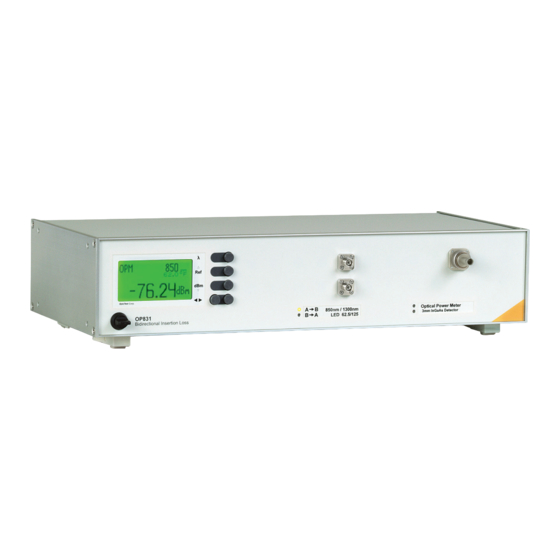
Page 9: Front Panel Operation Op831
A-B, B-A Mode: In bidirectional measurement mode the wavelength button toggles the source wavelength concurrently with the power meter calibration wavelength. For OP831 with a single wavelength source there is no wavelength to be selected, for dual wavelength implementations the wavelength selection is 850nm & 1300nm for multimode, and 1310nm &... - Page 10 The mode selection switches between the following modes: Optical Power Meter The OP831 operates as a standard optical power meter measuring absolute or relative power. In this mode the dBm button switches the instrument into absolute mode. The Ref button switches the instrument to relative mode (also dB mode on other instruments).
-
Page 11: Display Operation Op831
OP831 Display Operation – OP831 Depending on the selected mode the display shows different measurement parameters and results. OPM Mode – Power Meter Mode Wavelength Mode Indicator Indicator Absolute Reference Power Power Reading Inser tion Loss Reading Internal (ambient) Temperature... - Page 12 OP831 Display Operation – OP831 Bidirectional Insertion Loss Reference Source Indicator Wavelength Absolute Power in A-B direction Mode Indicator, Bidirectional Indicator, Reference Indicator Shows the current selected mode: OPM, A-B, B-A, Ref Wavelength Displays the currently selected calibration wavelength of the source wavelength used to measure in bidirectional mode.
-
Page 13: Measurements Instructions
Connect two reference cables as shown, please note that the use of quality reference cables is essential, a high loss from the reference connection will grossly dilute the measurement result of the actual cable. OP831 Bidirectional Insertion Loss 2x2 switch Laser... -
Page 14: Insertion Loss Measurement In A-B Direction And B-A Direction
OP831 Insertion Loss Measurement in A-B Direction and B-A direction Connect the cable to be tested as shown: OP831 Bidirectional Insertion Loss 2x2 switch Laser cable reference under cables test The display of the A-B measurement will show the insertion loss of the connected cable. -
Page 15: Usb Control Of The Op831
OP831 USB Control of the OP831 The OP831 can be controlled via the USB bus. Upon request, OptoTest can supply the appropriate DLLs along with sample programs to facilitate the software creation process. For these DLLs please contact sales@optotest.com. 14 of 15... -
Page 16: Warranty Information
OP831 Warranty Information OptoTest Corp. warrants this product to be free from defects in material and workmanship for a period of two years from date of shipment. During the warranty period we will, at our option, either repair or replace any product that proves to be defective. To exercise this warranty contact OptoTest Corp. - Page 17 1.805.987.1700...
Need help?
Do you have a question about the OP831 and is the answer not in the manual?
Questions and answers