Table of Contents
Advertisement
Quick Links
- 1 Model Description
- 2 Preventive Maintenance & Specifications
- 3 Basic Winch Operation and Trouble Shooting
- 4 Winch Removal and Installation
- 5 Wire Rope Installation & Welding Procedure
- 6 Bevel Pinion & Hydraulic Pump Service
- 7 Cable Drum Group
- 8 Control Valve Service (Current Production)
- Download this manual
Advertisement
Table of Contents

Related Manuals for Paccar PA55


Summary of Contents for Paccar PA55
- Page 1 SENR5358-04 SERVICE MANUAL WINCH MODELS PA55 & PA56 PACR WINCH DIVISION P.O. BOX 547 BROKEN ARROW, OK U.S.A. 74013 PC-210 R4 PHONE (918) 251-8511 FAX (918) 259-1575 5/2010 www.paccarwinch.com Printed in U.S.A.
-
Page 3: Table Of Contents
PACCAR winch or this publication, please contact your nearest Caterpillar dealer or the PACCAR Winch Service Department at 1-918-251-8511, Monday - Friday, 0800 hrs - 1630 hrs CST, or by fax at 1-918-259-1575, or by e-mail at winch.service@paccar.com. Provide the complete winch MODEL NUMBER and SER- IAL NUMBER when making inquiries. -
Page 4: General Safety Recommendations
8. Use only GENUINE PACCAR parts. Do not use parts from other winch manufacturers on your PACCAR 9. Do not operate the winch under loads that exceed the winch. -
Page 5: Model Description
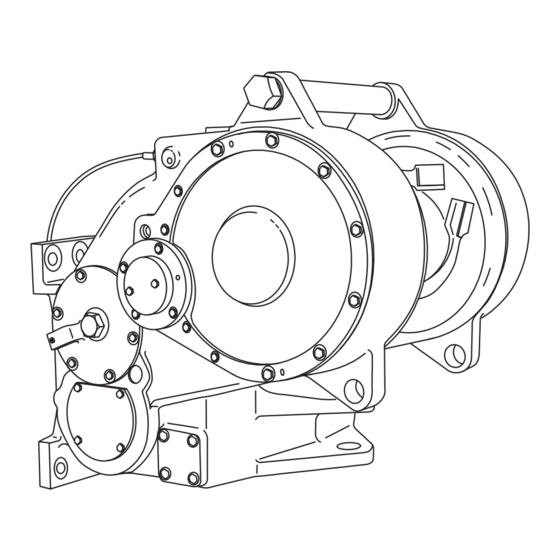
MODEL DESCRIPTION The PACCAR Power Shift Winch is a single drum unit The Model PA55 may have either a 3-shaft or 4-shaft which mounts on the rear of a crawler tractor. It is driven gear train configuration depending upon the tractor... -
Page 6: Preventive Maintenance & Specifications
Important: Always refer to the serial number and model number when requesting information or service parts. PREVENTIVE MAINTENANCE & SPECIFICATIONS A regular program of preventive maintenance for your PACCAR winch will minimize the need for emergency Vent servicing and promote long product life and trouble-free Filter Plug service. - Page 7 tractor and winch in level position. Oil must be visible in the upper half of the sight gauge. If an oil level plug is used in place of the sight gauge, the oil level should be at the bottom of the level plug hole. Add oil as required Shield 118-6283 Shield 29020 through the fill plug at top of winch case.
- Page 8 warms up. If the light stays on, this indicates a restricted With controls in Brake-On (neutral) remove gauge from filter element, sending unit stuck in the bypass position or “B” port and securely install plug into brake housing. accidentally grounded sending unit wire. Install access cover plate and tighten eight ½...
- Page 9 Your lubricant supplier should assure you his product meets this specification. If there is any doubt as to the suitabil- ity of a lubricant, contact the Paccar Winch Service Department, providing a detailed copy of the product specifications. Cold start-up in this ambient temperature range requires extended equipment warm-up to prevent erratic clutch and brake operation which may result in property damage, injury or death.
- Page 10 SPECIFICATIONS Unit weight (without oil, cable or specific tractor adapters) ....Approximately 1,960 lbs (885 kg) Gear Ratio Available Bevel Gear Ratio 1.00:1 1.27:1 1.64:1 2.11:1...
-
Page 11: Basic Winch Operation And Trouble Shooting
Reel-in (forward) or hydraulically released multiple-disc oil brake. Reel-out (reverse) clutches and release the spring A PA55 standard PTO winch may be either 3-shaft or 4- applied multi-disc oil brake. shaft gear train configuration depending upon the tractor... - Page 12 TROUBLE-SHOOTING most hydraulic system tests. The test port requires an SAE-4 JIC hose adapter. If the winch does not operate correctly, perform a visual inspection of obvious faults, such as leaking oil, loose, damaged, or broken parts. If cause of trouble is not read- ily apparent, check operation of winch in each function to Discharge accumulator oil supply before removing any help determine the trouble.
- Page 13 TROUBLE PROBABLE CAUSE CORRECTIVE ACTION 1a. See corrective action for D. 1. Brake not releasing as clutch is Tractor engine or torque converter applied due to low hydraulic pres- stalls when attempting to Reel-in or sure. Reel-out. 1b. Shuttle valves in control valve 190-235 psi (1310-1620 kPa) is worn or sticking allowing excessive required to release brake.
- Page 14 TROUBLE PROBABLE CAUSE CORRECTIVE ACTION 1. Friction discs worn and steel 1. Replace disc and plates. Adjust Clutch damaged or defective. discs warped. system relief pressure to 390-410 psi (2689-2827 kPa). Instruct operator not to “feather” clutch under load. 2. Clutch piston return springs weak 2.
- Page 15 TROUBLE PROBABLE CAUSE CORRECTIVE ACTION Winch gear train bearing and/or gear 1. Defective bearings and/or gear. 1. Replace components. Operate winch within limits, using multi-part failure. line and sheave blocks on excessive line-pull requirements. 2. Gear train overloaded or shock 2.
- Page 16 TROUBLE PROBABLE CAUSE CORRECTIVE ACTION 2. System pressure will intermittently 2a.See corrective action for K1a. rise above adjusted relief pressure 2b.Differential unloading pilot car- and fail to recycle below cut-in pres- tridge piston is sticking in bore caus- sure. ing system (accumulator circuit) pressure to rise too high before off- seating check-ball, then holding check-ball offseated too long before...
-
Page 17: Winch Removal And Installation
WINCH REMOVAL AND INSTALLATION Before starting any repair procedures, be sure to thor- Carefully remove the hitch pins and clevis pins which con- oughly clean the parts to be removed and adjacent areas nect the control cables to the control valve spools. on the tractor to avoid entry of dirt into the winch. - Page 18 Carefully install winch on tractor while guiding winch PTO Move the lever slightly to expose the wrench flats on the pilot into tractor and rotating bevel gears to align PTO plunger. shaft splines. CAUTION Install winch top access cover plate. Fill winch to proper level with recommended oil.
-
Page 19: Wire Rope Installation & Welding Procedure
PA56 = 1 in. (25 mm) INSTALLATION OF SPIRAL FERRULES Re-usable, field-installed spiral ferrules are not supplied with all Paccar winches. These ferrules are for use with stan- dard six-strand, IWRC (Independent Wire Rope Core) type wire rope. Refer to ferrule selection chart in the “Specifications”... -
Page 20: Bevel Pinion & Hydraulic Pump Service
BEVEL PINION AND HYDRAULIC PUMP SERVICE The bevel pinion, bevel gears and hydraulic pump are turning whenever the tractor PTO shaft is turning. The bevel pinion transmits torque from the PTO shaft to the bevel gears, clutch shaft and winch gear train. Proper adjustment of bevel pinion/bevel gear back-lash and tooth contact pattern is essential for quiet operation and long component life. - Page 21 BEVEL PINION ASSEMBLY Lubricate and install O-Ring (5) onto the bevel pinion against the bearing cone. Install seal spacer (9) over the Lubricate and install o-ring (18) into the groove in the bevel pinion with internal tapered edge toward the bear- bore of the bevel pinion (16).
- Page 22 2. Remove access cover on right hand side of winch and locate pump port on control valve labeled “P”. Remove –8JIC pump line from the tee in the pump port of the Preferred control valve. Contact Pattern 3. Attach pump line to the gauge side of the gate valve or flow meter.
- Page 23 PUMP INSTALLATION Lubricate entire pump assembly with recommended oil. Coat the capscrew threads with Loc-tite 242 or equivalent and evenly tighten to 100-110 lb•in by 25•lb in (11.3-12.4 N•m by 2.8 N•m) increments in a cross pattern. When properly installed, there will be a slight gap, .005- .040 in.
-
Page 24: Clutch Shaft Service
CLUTCH SHAFT SERVICE DESCRIPTION The clutch shaft assembly contains or supports the two bevel gears, the Reel-in and Reel-out clutches, the brake hub and the first reduction pinion gear. OPERATION The bevel gears are continuously driven by the bevel pin- ion and, when no clutches are applied, spin freely on nee- dle roller bearings. - Page 25 you both move the clutch shaft assembly out through the brake opening. Move the clutch shaft assembly out of the winch case far enough to place a lifting sling between the bevel gears. Using a wood block, bump the end of the clutch shaft at the left hand side of the winch to unseat the brake assem- bly.
- Page 26 ITEM DESCRIPTION QTY. O-Ring (part of item 14) Bearing Cup Ball Bearing - STD PTO Bearing Cup Bearing Cone Needle Bearing - Inner Race Thrust Bearing Needle Bearing - Inner Race ITEM DESCRIPTION QTY. Bearing Cone Thrust Bearing, Shoulder Spacer Capscrew, Hex Head Back-up Washer Capscrew, Hex Head...
- Page 27 ASSEMBLY Thoroughly clean and carefully inspect all components prior to assembly. If a component’s condition is question- able – replace it! Due to machining tolerances, installation of any new com- ponents listed below will alter the original shim pack used between the bevel gears to establish the required back- lash between the bevel gears and bevel pinion.
- Page 28 Bevel Gear Clutch Assembly Assembly Bearing Cone Brake Spacer Bearing Race Rotary Measure and record dimension R1, R2, R3 and R4 bevel Seal gear bearing inner race (6) thickness. Shaft Needle Back-up Bearing Ring Retainer O-Ring The shim pack thickness, Z, to use in re-assembly of the clutch shaft is the total mounting distance of the bevel gears M1 and M2 plus the total thickness of the thrust bearing assemblies B1 and B2 less the total thickness of...
- Page 29 (31) are supported by the winch case. the remaining components on the gear side of the shaft. The PA55 and PA56 winches are fitted with a rollpin (38) Lubricate and install two inner bearing races (6) onto the driven into outside surface of the bevel gear bearing car- shaft.
- Page 30 Lubricate and install o-ring (16) into groove of winch case oil port and into groove of bearing carrier (35). With correct bevel gear tooth contact pattern established, Use the original shim set or a new shim set of the same move clutch shaft assembly to the right (brake side).
-
Page 31: Clutch Assembly Service
CLUTCH ASSEMBLY SERVICE Two identical clutch assemblies are mounted on the The bevel pinion carrier and pump assembly is removed clutch shaft: One is used to Reel-in, the other for Reel- from the front of the winch and, after removal of the brake out. - Page 32 ITEM DESCRIPTION QTY. PLUG (-4 ORB) Slotted STEEL CHECK BALL Clutch SPRING Assembly O-RING O-RING RETAINING RING RETAINING RING SPRING RETAINER CHECK VALVE SEAT PRESSURE PLATE CLUTCH HOUSING ITEM DESCRIPTION QTY. DISC - FRICTION DISC - STEEL CLUTCH PISTON O-RING BACKUP RING BACKUP RING WAVE SPRING...
- Page 33 ASSEMBLY Thoroughly clean and inspect all components prior to assembly. Install the steel check-ball (2) into the back side of clutch housing (11). Lightly coat threads of check valve seat (9) with Loc-tite 242 and install flush with the surface of the clutch housing.
- Page 34 Remove the screwdrivers and push the pressure CAUTION plate down against the disc. Again, measure from the top of the pressure plate to the top of the disc. After installation of the clutch, be sure to remove the Call this dimension “B”. two 3/8 in.
-
Page 35: Brake Assembly Service
BRAKE ASSEMBLY SERVICE NOTE: In June of 2001 Paccar began using a new slotted housing brake assembly in winches (Serial Whenever the operator applies a clutch or shifts to Number 0100878 and higher). Basic service “Brake-Off”, hydraulic pressure is directed to the brake... - Page 36 Install the bearing carrier (18) onto the brake housing ing ring (8). while aligning the oil ports between the two housings. Install the two 3/8 in. capscrews (2) and tighten to 31 lb•ft The PA55 and PA56 brake pack requires no adjustment. (42 N•m) torque.
- Page 37 BRAKE ASSEMBLY TEST PROCEDURE INSTALLATION The following test procedure may be used to check the Refer to “Clutch Shaft Service” for additional information. condition of the brake piston seals and the actual pres- Install three o-rings in the grooves on the brake housing sure required to fully release the brake.
-
Page 38: Idler Shaft Group
IDLER SHAFT GROUP IDLER SHAFT GROUP WITH FREESPOOL SHOWN ITEM DESCRIPTION QTY. Bearing Assembly - Inner Bearing Assembly - Outer O-Ring Lock Plate Capscrew, Hex Head Capscrew, Hex Head Capscrew, Hex Head ITEM DESCRIPTION QTY. Plug Shift Rail Thrust Washer Yoke Adjuster Jam Nut... - Page 39 REMOVAL With a lifting fixture or suitable sling, remove the second reduction drum drive gear and shaft assembly from the winch case. Gear and shaft assembly weight is approxi- Drain oil from winch as described in the “Preventive mately 125 lb (56 kg). Maintenance”...
- Page 40 Carefully move the gear and pinion assembly into the ASSEMBLY drum drive gear opening and remove from winch case. FREESPOOL LINKAGE INSTALLATION If the freespool shift linkage was removed from the winch case, install the linkage as follows: Install jam nuts (18) on rod ends (19) until nuts bottom on the threads by the rod eye.
- Page 41 ASSEMBLY FREESPOOL UNITS ONLY ALL UNITS Bearing Cone First Reduction Thrust Washer Gear Clutch Collar Floating Bushing Second Reduction Pinion Install the shift yoke and collar assembly in the winch case, placing the shift yoke in the groove of the freespool Place the second reduction pinion (12) on a flat surface clutch collar (29) and shift collar shoulder screw in the slot with the stepped end facing up.
-
Page 42: Fourth Shaft Group
bearing carrier cover and install it into the winch case. adjuster can no longer be tightened. Back the adjuster Apply thread sealant to the capscrews and install them out no more than 1/16 turn maximum and secure with finger tight. DO NOT tighten capscrews at this time. lock plate and capscrews. - Page 43 DISASSEMBLY thrust washer contact areas should be free from any sur- face irregularities that may cause abrasions or friction. Drain oil from winch as described in the “Preventive The gears and shaft should be inspected for abnormal Maintenance” section of this manual. wear or pitting.
-
Page 44: Cable Drum Group
CABLE DRUM GROUP ITEM DESCRIPTION QTY. Ball Bearing Bearing Cup Bearing Cone Capscrew, Hex Head DISASSEMBLY Capscrew, Hex Head O-Ring Retaining Ring Retaining Ring Oil Seal Discharge accumulator oil supply before removing any Capscrew, Socket Head Cable Drum hydraulic lines or servicing winch. Personal injury may Gear, Second Reduction result from sudden release of oil pressure. - Page 45 CAUTION Hot oil may cause injury. Make certain the oil has Use a pry bar between the bearing carrier cover and the cooled to a safe temperature (less than 110°F- 43°C) second reduction drum drive gear to unseat the ball before servicing the winch.
- Page 46 remove the drum bearing carrier. 75 lb•ft (102 N•m) torque. Remove capscrews (4) from the left hand drum bearing Attach a dial indicator to the left hand bearing carrier and carrier (15) and lube tube clamps. Using jackscrews, position the indicator stem against the retaining ring (8) in remove the drum bearing carrier.
-
Page 47: Control Valve Service (Current Production)
CONTROL VALVE SERVICE (Current Production) The control valve performs two essential duties: 1. Maintains a relatively constant pressure oil supply for reliable operation of the brake and clutches. 2. Converts the operator’s mechanical signals, from con- trol levers and cables, into hydraulic force to apply the directional clutches and release the spring applied brake. - Page 48 Pressure Maintenance System UNLOADING The pressure maintenance system operates continuous- ly to keep the directional control system supplied with oil at 320-400 PSI (2210-2760 kPa) for reliable brake release and clutch application. The pressure mainte- nance system consists of the following components: CV –...
- Page 49 The pressure maintenance system will cycle between “Charging” and “Unloading” every 30 seconds to more than ten minutes depending on PTO speed (pump flow) Discharge accumulator oil supply before removing any and control functions selected. hydraulic lines or servicing winch. Personal injury may result from sudden release of oil pressure.
- Page 50 BRAKE ON REEL - IN REEL - OUT CLUTCH CLUTCH The operator’s control lever is in the centered, brake-on, of the valve through port T will pass through the brake “neutral” position. Supply oil from the pump, flows through assembly port F to cool and lubricate the brake discs. The the filter and enters the valve at port P.
- Page 51 The act of releasing the brake consumed some of the When the operator returns the control lever to the brake- control oil stored in the accumulator and caused a on position, the brake control valve spool will spring cen- momentary drop in pressure. This pressure drop signaled ter and exhaust the brake release oil pressure from the the differential pressure unloading valve (PU) to close brake circuit.
- Page 52 REEL-OUT REEL - OUT REEL - IN CLUTCH CLUTCH When the control lever is pushed away from the operator stored supply in the accumulator will signal the pressure into the reel-out position, the spool of the CLV is pulled maintenance system to refill the accumulator and the outward to direct control oil pressure from the center control oil pressure to 320 - 400 PSI (2210 –...
- Page 53 Cartridge seal kits are available from PACCAR Service Clutch Control Valve (CLV) and Brake Control Valve Parts. If there is any evidence of contamination damage (BRV) Cartridges to the cartridges, they must be replaced.
- Page 54 During normal operation, the control pressure will decay Adjust the control cable to achieve the highest pressure, approximately 15-20% from the peak pressure then approximately the same as the main system pressure, charge back up to 390 – 410 PSI when the valve cycles. when the control lever is latched in the brake-off position.
-
Page 55: Control Valve Service (Early Production)
CONTROL VALVE SERVICE (Early Production) The control valve performs two essential duties: 1. Maintains a relatively constant pressure oil supply for the directional controls. 2. Converts the operator’s mechanical signals, from control cables, into hydraulic force to apply the direc- tional clutches and release the spring applied brake. - Page 56 PRESSURE MAINTENANCE SYSTEM UNLOADING The pressure maintenance system operates continuously to keep the directional control system supplied with oil at To Control 340-400 psi (2344-2758 kPa) for reliable brake release Cartridges and clutch application. The pressure maintenance system consists of the following sub-assemblies: Item 4 check valve cartridge Item 5 differential unloading pilot valve cartridge Item 6 differential unloading pilot valve adjusting screw...
- Page 57 DIRECTIONAL CONTROL SYSTEM CAUTION WARNING The direction control system consists of the following sub- Discharge accumulator oil supply before removing any assemblies: hydraulic lines or servicing winch. Personal injury may Item 1 - directional control cartridge result from sudden release of oil pressure. To dis- charge the accumulator, stop engine, slowly cycle Item 2 –...
- Page 58 BRAKE ON To Control Cartridges Directional Control Cartridge Brake Control Cartridge To Brake Shuttle Valves Not used in later Orifice valves for 50B/70A Flush to reservoir From Pump through brake cavity Reel-In Reel-Out Clutch Clutch Supply oil from the pump enters the control valve through being used by the clutches or brake.
- Page 59 Reel-In Spool Travel 7/16 in. To Control Cartridges Directional Control Cartridge Brake Control Cartridge To Brake Shuttle Valves Not used in later Orifice valves for 50B/70A Flush to reservoir From Pump through brake cavity Reel-In Reel-Out Clutch Clutch Pulling the power shift control handle toward the operator shuttle valve check balls must seal tightly to prevent a has pushed the directional control spool inward.
- Page 60 The shuttle valves will function in the same manner as The pressure maintenance system will recharge the con- described earlier. trol circuit as required to maintain the pressure between 340 and 400 psi (2344 and 2758 kPa). The excess oil When the control handle is released, the directional con- flow, not required by the control circuit, is directed through trol spool will return to “Brake-on”, release the Reel-Out...
-
Page 61: Accumulator Service
Differential unloading pilot valve cartridge seal kits are Install the oil lines to the bottom of the valve. available. Install the control cables to the valve spools and verify Unloading poppet assembly (7): proper adjustment as described in the “Winch Removal and Installation”... - Page 62 The spring-type accumulator DOES NOT require any periodic recharging or servicing. Rod extension at no pres- VENT HOLE sure is 0.06 in. (1.5 mm). Rod extension at 400 psi (2760 kPa) is approximately 1.57 in. (40 mm) -8 O-Ring Boss Port (3/4-16) ITEM DESCRIPTION...
Need help?
Do you have a question about the PA55 and is the answer not in the manual?
Questions and answers