Table of Contents
Advertisement
Quick Links
SERVICE MANUAL
Visit our Web site at www.paccarwinch.com for the most comprehensive collection of winch, hoist, and drive
information on the Internet. Most publications and specification sheets are available for downloading.
LIT2753
October 2018
Printe d in USA
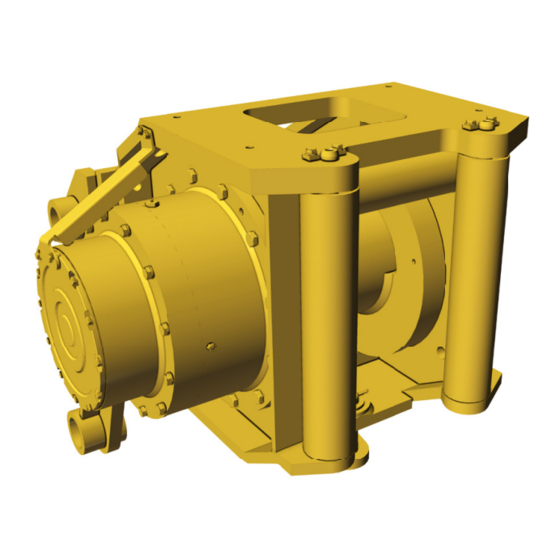
H200 Tail Winch
WRITE WINCH SERIAL NUMBER BELOW
First 2 numbers indicate
year manufactured
For serial number location see page 3
1
H200
©2018 PACCAR Inc.
All rights reserved
Advertisement
Table of Contents

Related Manuals for Paccar Carco H200


Summary of Contents for Paccar Carco H200
- Page 1 Visit our Web site at www.paccarwinch.com for the most comprehensive collection of winch, hoist, and drive information on the Internet. Most publications and specification sheets are available for downloading. LIT2753 October 2018 ©2018 PACCAR Inc. Printe d in USA All rights reserved...
-
Page 2: Table Of Contents
Brake Cylinder Lifting Fixture ..................47 FOREWORD Managing Waste PACCAR Winch believes in a life-cycle approach to our products. We encourage best practices regarding “Going Green” — making environmentally responsible decisions to “reduce, reuse, and recycle.” • At the end of the winch’s useful life, it is highly recommended to drain and recycle any oil remaining in the equipment. -
Page 3: Model Identification
NOTE: The hydraulic motors and selected gear ratios on CARCO H200 winches are specifically configured for use on the intended tractor. The winch may not be suitable or advisable for use on anything other than the intended tractor. -
Page 4: Explanation Of Model Number
EXPLANATION OF MODEL NUMBER – – 500V GEAR MAXIMUM MOTOR RATIO RATING Hydraulic motor, two-speed 200,000-lb. first-layer line pull 500V 500:1 gear ratio TO ORDER: 1. List model and serial numbers of the winch. 2. Refer to cross-section drawing (exploded view), select the component(s) needed, and note item number. 3. - Page 5 GENERAL SAFETY RECOMMENDATIONS 3. Assure that personnel responsible for hand signals 14. The winches described in this manual are neither are clearly visible and that the signals are thoroughly designed nor intended for use with or application to understood by everyone. equipment used in the lifting or moving of persons.
-
Page 6: Theory Of Operation
DESCRIPTION OF WINCH BASIC WINCH OPERATION The winch assembly consists of six basic component The CARCO H200 winch contains a hydraulic motor and groups: gear ratio specifically selected to match the winch to the hydraulic power of the tractor. This allows the winch to 1. - Page 7 THEORY OF OPERATION control valve is moved into the reel-out position, the spool in the brake valve remains closed until sufficient pilot pres- sure is applied to the end of the spool to shift it against the spring pressure and open a passage. After the spool valve cracks open, the pilot pressure becomes flow dependent and modulates the spool valve opening which controls the reel-out speed.
- Page 8 THEORY OF OPERATION The hydraulic cylinder, when pressurized, will release the REEL-IN spring pressure on the brake discs, allowing the brake Moving the control lever in the direction of tractor forward discs to turn freely. movement provides a signal to direct the oil to the winch motor to pull the cable and load in to the winch.
- Page 9 THEORY OF OPERATION on the work ports (A and B) increases due to the load ap- CAUTION plied to the winch gear train. When there is little or no load on the winch, the motor rotating group will remain at the preset minimum displacement.
-
Page 10: Preventive Maintenance
PREVENTIVE MAINTENANCE A regular program of preventive maintenance for your GEAR CASE OIL CHANGE CARCO winch will minimize the need for emergency ser- vicing and promote long product life and trouble-free ser- WARNING vice. The service intervals suggested in this manual will opti- Hot oil may cause injury. -
Page 11: Specifications
If there is any doubt of the suit- Bare drum rated line pull*: 200,000 lbs. (90,718 kg) ability of a lubricant, contact the PACCAR Winch Service Bare drum rated line speed: 37.1 ft./min. (11.3 meters Department, providing a copy of the product specifications. -
Page 12: Recommended Planetary Gear Oil
RECOMMENDED PLANETARY GEAR OIL Field experience, supported by engineering endurance tests, indicates that the use of the proper gear oil and a program of regular preventive maintenance will help provide extended gear-train life and reliable winch-brake perfor- mance. For this reason, CARCO has published the following specifications to assist in determining which lubricant is best suited to your application. -
Page 13: Wire Rope Installation
WARNING Failure to use the proper type and viscosity of planetary gear oil may contribute to intermittent brake clutch slippage, which could result in property damage, severe personal injury, or death. Some gear lubricants contain large amounts of extreme-pressure (EP) and antifriction additives, which may contribute to brake clutch slippage or damage to brake friction discs or seals. -
Page 14: Troubleshooting
TROUBLESHOOTING After troubleshooting the winch and its hydraulic system as covered in the Troubleshooting section of this manual, and the problem is determined to be in the winch, disassemble the winch according to the Winch Disassembly section of this manual. TROUBLE PROBABLE CAUSE REMEDY... - Page 15 TROUBLESHOOTING TROUBLE PROBABLE CAUSE REMEDY TROUBLE “B” CONTINUED 3. The drum clutch piston seals may A. Disconnect the drum clutch release FROM PREVIOUS PAGE be leaking. hose from the drum clutch housing. Connect a hand pump with an accu- rate gauge and shut-off valve to the –6 adapter.
- Page 16 TROUBLESHOOTING TROUBLE PROBABLE CAUSE REMEDY Winch will not pull the rated load. 1. The hydraulic system relief valve A. Check system relief pressure as fol- may be set too low. The relief lows: valve may need repair or replace- ment. Install an accurate gauge into the trac- tor pump pressure port per the tractor manual.
- Page 17 TROUBLESHOOTING TROUBLE PROBABLE CAUSE REMEDY Winch runs hot. 1. Be certain the hydraulic system Same as D1A. temperature is not more than 200ºF (93ºC). Excessive hydraulic oil temperatures may be caused A. Plugged heat exchanger (where A. Thoroughly clean exterior and flush used).
- Page 18 TROUBLESHOOTING TROUBLE PROBABLE CAUSE REMEDY Winch chatters while pulling rated 1. Same as D1. A. Same as D1A. load. 2. Hydraulic oil flow to motor may be A. Same as E1B, C, D; operate engine at too low. full throttle. 3.
-
Page 19: H200 Major Parts Groups Cross-Section
H200 MAJOR PARTS GROUPS CROSS-SECTION Part number 88141... -
Page 20: H200 Major Parts Groups Components
H200 MAJOR PARTS GROUPS COMPONENTS Part number 88141 ITEM DESCRIPTION PART NO. QTY. Ratio group, H200-500 63418 Miscellaneous parts group H200 63420 Fairlead group 65297 Brake assembly, V 83107 Overrunning clutch assembly, V 83109 Hydraulic motor group H200A 63940 ADDITIONAL REFERENCE PUBLICATION cross-section diagrams... -
Page 21: Winch Removal And Installation
WINCH INSTALLATION WINCH REMOVAL For first-time installation, contact PACCAR Winch Engi- neering for your specific tractor. A detailed scope of work WARNING is put forth in this document and describes all tractor modi- fications and adaptation. -
Page 22: Winch Disassembly
WINCH DISASSEMBLY 1. Remove the wire rope from the cable drum BEFORE disconnecting the hydraulic lines from the winch motor. 2. Drain the gear case oil as described in the Preventive Maintenance section of this manual. Oil fill and vent Oil level Oil drain 3. - Page 23 WINCH DISASSEMBLY Drum clutch hose 168,169 159,160,161 171,172 8. Remove the secondary sun gear (Item 44) and inspect snap ring (143). 9. Remove the secondary carrier assembly (700). Remove thrust bearing set (2x 164 thrust race, 165 needle roller bearing). Refer to the Secondary Carrier Assembly Service section for service procedures. 10.
- Page 24 WINCH DISASSEMBLY 164,165 113,116 12. Remove the third sun gear (46) and the third carrier assembly (800). Use caution because the third carrier assembly weighs approximately 136 lbs. (62 kg). Refer to the Third Carrier Assembly Service section for service procedures. 13.
- Page 25 WINCH DISASSEMBLY 15. Remove thrust washer (Item 145) and wear plate (146), then inspect for wear or damage. 16. Support the drum in the winch housing by using wooden blocks or other suitable means. Once either the support adapter (147) or the brake (300) has been removed, the drum will no longer be supported in the frame. Make sure the drum is supported by means so that it remains stable in the housing during disassembly.
- Page 26 WINCH DISASSEMBLY 21. Remove the overrunning clutch (Item 400) from inside the brake assembly (300). Refer to the Overrunning Clutch Service section of this manual for service procedures. 22. Make sure the drum is well supported in the winch housing before removal of the brake assembly. 23.
- Page 27 WINCH DISASSEMBLY 26. Support the horizontal fairlead roller assembly (Item 201) with a wide-band sling or other positive-retention method. Remove the cap screws (207) and clip (205) that secure the roller assembly to the winch housing. Carefully remove the roller shaft (202) from the housing. Remove the roller assembly (201) and spacer washers (206) from each end of the roller assembly.
-
Page 28: Primary Planet Carrier Service
PRIMARY PLANET CARRIER SERVICE DISASSEMBLY ASSEMBLY 1. Apply light pressure to the thrust ring (Item 10) and re- 1. Install the bearing (57) into a planet gear (54). Place a move the retaining ring (11). Then remove thrust ring, thrust washer (56) on each side of the gear and insert brake plates, friction discs, and wave springs (7,8,9) the gear assembly into an opening in the carrier (53). -
Page 29: Secondary Planet Carrier Service
SECONDARY PLANET CARRIER SERVICE DISASSEMBLY ASSEMBLY 1. The preferred method of removing the planet gear pin 1. Liberally coat the bore of a planet gear (21) with a (Item 22) is to first remove the roll pin (26). This can good grade of oil soluble grease. -
Page 30: Third Planet Carrier Service
THIRD PLANET CARRIER SERVICE DISASSEMBLY ASSEMBLY 1. Replace final sun gear (95) by first inserting snap ring CAUTION (42). 2. For each gear, replace two sets of bearing cups (21), The third planet carrier assembly weighs approxi- bearing cones (70), and bearing spacer (19). Replace- mately 137 lbs. -
Page 31: Output Planet Carrier Service
OUTPUT PLANET CARRIER SERVICE DISASSEMBLY ASSEMBLY 1. Support the planet gear (15) on one of the thrust CAUTION washers (54) and install 21 rollers (53) at one end of the bore. Applying a light coating of grease on the bore and on the rollers aids in retention during assembly. -
Page 32: Drum Clutch Assembly Service
DRUM CLUTCH ASSEMBLY SERVICE DISASSEMBLY ASSEMBLY 1. Place the ring gear housing (28) on a clean work sur- CAUTION face with the large end facing down. 2. Install new quad rings (34,35) into the clutch piston The drum clutch assembly weighs approximately 620 (29) grooves. - Page 33 DRUM CLUTCH ASSEMBLY SERVICE DRUM CLUTCH ASSEMBLY PART NUMBER 83137 ITEM DESCRIPTION PART QTY. Clutch housing 111362 Clutch piston 29309 50461 Brake plate 72180 50497 Divider plate 72204 Pressure plate 29292 Retaining ring 29303 Quad-ring 106885 Quad-ring 106886 Clutch hub 29246 16574-0012 Sight gauge 70193...
-
Page 34: Brake Assembly Service
BRAKE ASSEMBLY SERVICE DISASSEMBLY 8. Check the cable drum bearing and seal surfaces on the outside of the brake housing for excessive wear or damage. CAUTION 9. Place each friction disc on a clean, flat surface and check for any distortion using a straightedge. The fric- The brake assembly weighs approximately 140 lbs. -
Page 35: Brake Assembly Pressure Test
BRAKE ASSEMBLY SERVICE ASSEMBLY 6. Lubricate the O-rings and backup rings (309, 310, 311, 312) with light grease or petroleum jelly. Install O-rings and backup rings into the piston grooves. Be sure to CAUTION install the backup rings to the outside of the O-rings toward the ends of the piston. -
Page 36: Brake Valve Service
BRAKE VALVE SERVICE The brake valve is a reliable hydraulic valve with internal DISASSEMBLY components manufactured to close tolerances. Due to the close tolerances and mating of components, the valve 1. Remove the pilot orifice (Item 9) from the brake re- housing, spool, piston and check poppet are not available lease (BR) port using a 5/32-inch Allen wrench. - Page 37 BRAKE VALVE SERVICE 4. Remove spool plug (Item 4) and carefully remove ASSEMBLY spool (5). 1. Install new O-rings on the plug and spring retainers. 2. Install new O-rings and backup rings on the spool. It is important that the backup ring is on the correct side of its O-ring.
-
Page 38: Overrunning Clutch Service
OVERRUNNING CLUTCH SERVICE ITEM DESCRIPTION Inner race Outer race Overrunning clutch Ball bearing Retaining ring 16314-137 Retaining ring NOTE: Outer race, inner race, and overrunning clutch WARNING are NOT SOLD individually as replacement parts. If any of these parts require replacement, the entire overrunning clutch assembly must be replaced. -
Page 39: Cable Drum Service
CABLE DRUM SERVICE DISASSEMBLY ASSEMBLY 1. Chill the inner bearing cup in dry ice to shrink the di- CAUTION ameter to aid installation. Install the bearing cup into the cable drum bearing bore. Use a .002 inch (.05 mm) feeler gauge to make certain the cup is fully seated Cable drum weighs approximately 1,000 lbs. - Page 40 CABLE DRUM SERVICE ITEM DESCRIPTION QTY. Cable drum Bearing, tapered roller set Spacer ring Oil seal Bearing, spherical Oil seal...
-
Page 41: Winch Assembly
WINCH ASSEMBLY CAUTION CAUTION The cable drum is supported in the winch housing The support adapter (147) weighs approximately by bearings on the output ring gear and the brake 600 lbs. (272 kg.) The output ring gear (14) weighs housing. If either of these components is removed, approximately 320 lbs. - Page 42 WINCH ASSEMBLY 3. Install the brake assembly into the bore on the right of the housing using the cap screws and washers (Items 149, 150). Apply a light coating of multipurpose grease to the seal and on the brake housing pilot. Be careful not to dam- age the oil seal in the cable drum during installation.
- Page 43 WINCH ASSEMBLY 11. Install the third planet carrier assembly (800). The third planet carrier assembly weighs approximately 136 lbs. (62 kg). 164,165 113,116 12. Install the intermediate shaft (62) through the cable drum and into the brake clutch. Make certain the shaft is fully inserted into the brake clutch inner race.
- Page 44 WINCH ASSEMBLY 17. Install the thrust bearing set (2x 168 thrust washers, 169 thrust bearing). Install the first of two retaining rings (Item 166) onto the intermediate shaft. Use a light coat of multipurpose grease on the thrust bearing set. 18.
- Page 45 WINCH ASSEMBLY 24. Install the horizontal fairlead shaft and roller assembly into the winch housing. Insert the shaft in to the housing from the left, or gear side. Make certain spacer washers are installed at both ends of the fairlead roller. Install the clip, cap screws, and washers.
- Page 46 WINCH ASSEMBLY WARNING Incorrect fastener tightening, both under and over tightening, can result in failure of the winch mounting fastener(s), loss of winch, loss of load, other property damage, and/or personal injury or loss of life. 28. Fill the winch to the proper level with the recommended oil as specified in the Preventive Maintenance section. Oil fill and vent Oil level...
-
Page 47: Brake Cylinder Lifting Fixture
BRAKE CYLINDER LIFTING FIXTURE LIFTING FIXTURE 0.8125 Diameter All dimensions in inches 12.0 Diameter 12.0 9.843 This piece can be a solid bar or piece of heavy This piece can be a solid bar or piece wall pipe or tubing. of heavy wall pipe or tubing. - Page 48 LIT2753 ©2018 PACCAR Inc. October 2018 All rights reserved Printe d in USA...
Need help?
Do you have a question about the Carco H200 and is the answer not in the manual?
Questions and answers