Table of Contents
Advertisement
Quick Links
INSTALLATION AND SERVICE MANUAL
Visit our Website at www.paccarwinch.com for the most comprehensive collection of winch, hoist, and drive
information on the Internet. Most publications and specification sheets are available for downloading.
LIT2736
February 2019
Printed in USA
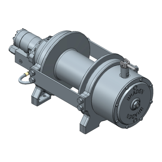
TR20A
Recovery Winch
WRITE WINCH SERIAL NUMBER BELOW
First 2 numbers indicate
year manufactured
For serial number location see page 3
TR20A
©2019 PACCAR Inc.
All rights reserved
Advertisement
Table of Contents

Related Manuals for Paccar Braden TR20A


Summary of Contents for Paccar Braden TR20A
- Page 1 Visit our Website at www.paccarwinch.com for the most comprehensive collection of winch, hoist, and drive information on the Internet. Most publications and specification sheets are available for downloading. LIT2736 ©2019 PACCAR Inc. February 2019 All rights reserved Printed in USA...
-
Page 2: Table Of Contents
Read this entire publication and retain it for future reference. For inquiries regarding your BRADEN TR20A recovery winch or this publication, please contact PACCAR Winch Techni- cal Support at 918-251-8511, Monday through Friday, 8:00 a.m. to 4:30 p.m. (CST). -
Page 3: Model Identification
MODEL IDENTIFICATION Model numbers and serial numbers are stamped on a nameplate located to the left of the hydraulic motor. Always refer to the model number and serial number when requesting information or service parts. EXPLANATION OF MODEL NUMBER - 080 - 01T - LA - LM MOTOR APPLI- GEAR... -
Page 4: Glossary
GLOSSARY Brake Valve — A hydraulic counterbalance valve should be connected to the reel-in port of the hydraulic motor. It allows oil to flow freely through the motor in the winching direction. When oil pressure tries to rotate the motor in the reel-out direction, the brake valve blocks the flow of oil out of the motor until the internal static brake is released. -
Page 5: General Safety Recommendations
13. Do not weld on any part of the winch without approval etc.) is either lowered to the ground or blocked securely from PACCAR Winch Engineering. before servicing, adjusting, or repairing winch. 14. Use recommended hydraulic oil and gear lubricant. - Page 6 GENERAL SAFETY RECOMMENDATIONS 25. Deadman controls, which automatically shut off power 29. All winch controls shall be located within easy reach of to the winch whenever the operator leaves his station the operator. The controls shall be installed in such a or releases the winch control lever, should be installed location that the operator is removed from the electrical whenever practical.
-
Page 7: Theory Of Operation
THEORY OF OPERATION DESCRIPTION OF WINCH DESCRIPTION OF DUAL BRAKE SYSTEM The winch consists of three basic assemblies: Dynamic Brake 1. Hydraulic motor, brake valve block and counter- balance cartridges The dynamic brake system consists of two basic compo- 2. Static brake assembly nents: 3. - Page 8 THEORY OF OPERATION OPERATION OF DUAL BRAKE SYSTEM to open the counterbalance cartridge. The extent to which the cartridge opens will determine the amount of oil that can flow through it and the speed at which the cable drum will Because the static brake on this winch is effective both di- turn.
-
Page 9: Free-Spool Clutch Instructions
FREE-SPOOL CLUTCH INSTRUCTIONS WARNING Visually check that clutch and clutch handle are fully engaged, before operating the winch drum under load. Do not attempt to move the clutch shift handle with a load on the cable. Do not use “cheaters” to extend the shift handle length or other means to apply undue force on the shift handle. A partially engaged drum clutch may jump out of engagement causing a sudden loss of load control which may result in property damage, severe personal injury, or death. -
Page 10: Winch Installation
90°F (–12°C and 32°C), use SAE 10W; for applica- formance and long hydraulic system component life. tions colder than 10°F (–12°C), contact PACCAR Winch Technical Support. The use of multiviscosity oils is gener- Oil having 150 to 330 SUS viscosity at 100°F (38°C) and ally not recommended. -
Page 11: Wire Rope Installation
WIRE ROPE INSTALLATION A pass-through hole with two setscrews is used to secure WARNING the cable to the drum. The anchoring system is designed for 1/2-inch through 9/16-inch (12 mm through 14 mm) diameter cable. Rope anchors are NOT designed to hold rated loads. Winch loads applied directly to the cable anchor may CABLE WRAP DIRECTION cause the rope to pull free and result in the sudden... - Page 12 PREVENTIVE MAINTENANCE 2. Oil Change 4. Mounting Bolts The gear oil should be changed after the first 100 hours of Retorque winch mounting hardware after the first 100 hours operation, then every 1,000 operating hours or six months, of operation, then every 1,000 operating hours or six months, whichever occurs first.
- Page 13 Field experience, supported by engineering endurance tests, indicates that the use of the proper gear oil and a program of regular preventive maintenance will help provide extended gear-train life and reliable winch brake performance. For this reason, PACCAR Winch has published the following specifications to assist in determining which lubricant is best suited to your application.
-
Page 14: Troubleshooting
TROUBLESHOOTING The following troubleshooting section is provided as a general guide. You may also need to contact the original equipment manufacturer (OEM) for additional information. WARNING If a winch exhibits any sign of: • Erratic operation such as poor load control, load creep, or chatter •... - Page 15 PROBABLE CAUSE TROUBLE REMEDY 1. Same as A2. Same as A2. Oil leaks from vent plug. 2. Motor seal may be defective as a Case drain back pressure must not ex- result of high back pressure in the mo- ceed 100 PSI (6.9 bar) for gear motors tor case drain circuit or contaminated and 44 PSI (3 bar) for piston motors.
- Page 16 PROBABLE CAUSE TROUBLE REMEDY Trouble “D” Continued From B. Apply a stall pull load on the winch Previous Page while monitoring pressure. C. Compare gauge reading to winch specifications. Adjust relief valve as required. NOTE: If pressure does not increase in proportion to adjustment, relief valve may be contaminated or worn out.
- Page 17 PROBABLE CAUSE TROUBLE REMEDY 1. Same as D2. Same as remedies for Trouble D2. Winch chatters or surges while lifting rated load. 2. Hydraulic oil flow to motor may be Same as remedies for Trouble E2. too low. 3. Controls being operated too quickly. Conduct operator training as required.
-
Page 18: Tr20A Cross-Section
TR20A CROSS-SECTION Part number 09512... -
Page 19: Tr20A Components
TR20A COMPONENTS Part number 09512... -
Page 20: Winch Disassembly
WINCH DISASSEMBLY 1. Remove plug and drain oil. 4. Remove the free-spool clutch assembly. 2. Remove brake hose from brake valve and brake cylin- 5. Remove the gear housing cover by removing eight der housing. screws and eight washers. Remove O-ring. 3. - Page 21 WINCH DISASSEMBLY 9. Separate gear housing from drum support by removing 7. Remove tie plates by removing eight screws and eight eight screws and eight washers. washers. 10. Remove seal and bearing from each drum support. 8. Separate drum supports from drum.
-
Page 22: Brake Service
BRAKE SERVICE Disassembly Reassembly 1. Remove motor support by progressively loosening 1. Begin reassembly by placing the motor support face- eight capscrews, relieving the brake pack’s spring load. down on a workbench. Spring load will be relieved before capscrews disengage motor support. - Page 23 BRAKE SERVICE 7. Next, assemble the motor adapter to the end plate. To do this, lift the motor adapter up, then reach in through the motor adapter bore and hold the brake plates in position using your fingers. Flip the assembly over, and carefully install into the bore of the brake cylinder until the brake disc stack is flush against the spacer plate.
-
Page 24: Carrier Service
CARRIER SERVICE The primary and secondary carriers both use the same ser- Reassembly vice procedures described here. 1. Press new planet bushings into the gears, then apply oil Disassembly to the inside of the bushings. 1. Use a 3/16-inch drift to drive the roll pins into the center 2. -
Page 25: Recommended Fastener Torque
RECOMMENDED FASTENER TORQUE The general-purpose torque shown in the chart applies to SAE grade 5 and 8 bolts, studs, and standard steel full, thick, and high nuts. Higher or lower torques for special applications will be specified such as the use of spanner nuts, nuts on shaft ends, jam nuts, and where distortion of parts or gaskets is critical. - Page 26 THIS PAGE INTENTIONALLY LEFT BLANK...
-
Page 27: Metric Conversion Table
METRIC CONVERSION TABLE English to Metric Metric to English LINEAR inches (in.) X 25.4 = millimeters (mm) millimeters (mm) X 0.03937 = inches (in.) feet (ft.) X 0.3048 = meters (m) meters (m) X 3.281 = feet (ft.) miles (mi.) X 1.6093 = kilometers (km) kilometers (km) - Page 28 LIT2736 ©2019 PACCAR Inc. February 2019 All rights reserved Printed in USA...
Need help?
Do you have a question about the Braden TR20A and is the answer not in the manual?
Questions and answers