Table of Contents
Advertisement
Quick Links
Advertisement
Table of Contents

Related Manuals for Johnson Controls HMS1655


Summary of Contents for Johnson Controls HMS1655
- Page 1 HMS1655 Fume Hood Controller LIT-12013211 Installation Guide May 2024...
- Page 2 HMS1655 Controller settings HMS1655 Fume Hood Controller settings Fume hood name/number Unit Model Number and Serial Number (ESN) Sidewall sensor input Normal operating face velocity Occupied mode setpoint Unoccupied mode setpoint Decommissioned mode setpoint Face velocity deadband Analog output Operating mode (direct or PID)
- Page 3 HMS1655 Controller settings HMS1655 Fume Hood Controller settings PID constants Proportional constant (0.5% to 100.0 %) Integral constant (0.0% to 100.0 %) Derivative constant (0.0% to 100.0 %) Alarm limits Occupied mode high alarm setpoint Occupied mode high warning setpoint...
- Page 4 HMS1655 IMPORTANT: Failure to follow the wiring diagrams could result in damage to your equipment and could void your warranty. Under no circumstances should a single transformer be split between actuator and controller. Doing so will damage the actuator, the transformer, the controller, or all units.
-
Page 5: Table Of Contents
HMS1655 basic programming ..............................20 Introduction................................... 20 Setup Wizard ..................................20 Main display screen................................20 Re-configuring the HMS1655 Fume Hood Controller......................21 Calibrating face velocity sensor............................21 Configuring sash position sensor ............................21 Calibrating sash position sensor ............................21 Configuring sash settings ..............................22 Selecting sash control mode .............................. -
Page 6: Specifications
HMS1655 Specifications Figure 2: HMS1655 Fume Hood Controller Table 1: Electrical specifications Electrical Description 4 analog inputs 0mAdc to 20mAdc, 4mAdc to 20mAdc, 0Vc to 5Vc, 1Vdc to 5Vdc, 0Vdc to 10Vdc, or 2Vdc to 10Vdc 4 analog outputs 0mAdc to 20mAdc, 4mAdc to 20mAdc, 0Vc to 5Vc, 1Vdc to 5Vdc, 0Vdc to 10Vdc, or 2Vdc to 10Vdc 2 thermistor inputs NTC Type 2 or 3, 10kΩ... - Page 7 Table 4: Mechanical specifications Mechanical Description (H x W x D) HMS1655 display housing 5 in. x 3 in. x 1.13 in. (127 mm x 7.62 mm x 28.7 mm) HMS1655 controller housing 6.6 in. x 4.6 in. x 1.9 in. (167.64 mm x 116.84 mm x 48.26 mm)
-
Page 8: General
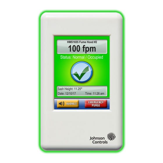
HMS1655’s Safety Halo ships from the factory with full brightness enabled, which you can dim or disable completely. The HMS1655 has a 3.2 in. diagonal full-color touchscreen display in portrait orientation (240 pixels x 320 pixels). The password- protected menu tree is very intuitive and simplifies the setup and configuration of the unit. The menus incorporate touch-based interfaces such as sliders, radio buttons, and dialog popups to facilitate the ease-of-use of the HMS1655. - Page 9 (NTC) Type 2 or Type 3 sensors. The HMS1655 provides three relay outputs. You can configure the outputs for either direct action or reverse action. You can also have a programmable delay associated to meet the specific needs of the required application.
-
Page 10: Installation
4. Use the two slots along the center line to mount the HMS1655 display backplate directly to a standard single-gang wall box. Use the backplate as a template to mark the mounting holes and the cable access hole at the center of the backplate. The preferred location is eye level, usually on one of the side bezel panels. -
Page 11: Mounting And Wiring
HMS1655 Mounting and wiring Figure 3: Display dimensions 1.13 in. 3 in. Left angle side view 5 in. Cable provided terminated at control unit Right side view Controller unit 5 in. 1.13 in. LIT-12013211... - Page 12 HMS1655 Figure 4: Display mounting hole pattern 3.04 in. ø 0.143 in. ø 0.750 in. 5.05 in. ø 0.143 in. LIT-12013211...
- Page 13 HMS1655 Figure 5: Controller mounting hole pattern (4 plcs) LIT-12013211...
- Page 14 HMS1655 Figure 6: Sensor mounting hole pattern and replacement in. DIA (typ 4 places) 3/8 in. DIA Figure 7: Sensor placement non by-pass type To ensure correct operation, reference the P1 Port to the laboratory air. Locate the sensor away from air turbulence, such as supply or exhaust diffusers.
- Page 15 HMS1655 Figure 8: Standard sidewall sensor (9-pin) preferred sensor mounting Exterior of fume hood Interior of fume hood Flexible tubing (3 ft. supplied) To ensure correct operation, reference the port to the +Vin laboratory air. Locate the sensor away from air turbulence, such as supply or exhaust diffusers.
- Page 16 HMS1655 Figure 10: Analog output to pneumatic actuator No connection to eld wiring Field wiring with space for number Internal wiring Screw wiring Controller configuration DIP switch settings Air ow to and from unit between the room and the corridor...
- Page 17 HMS1655 Figure 11: Analog output to electric actuator No connection to eld wiring Field wiring with space for number Internal wiring Screw wiring Air ow to and from unit between Controller configuration DIP switch settings the room and the corridor...
- Page 18 HMS1655 Figure 12: Analog input to single flow sensor 110VAC 24VAC No connection to eld wiring Field wiring with space for number Internal wiring Screw wiring Air ow to and from unit between Controller configuration DIP switch settings the room and the corridor...
- Page 19 HMS1655 Figure 13: Analog input sash position sensor Default input for sash sensor is AI-2. No connection to eld wiring Field wiring with space for number Internal wiring Screw wiring Controller configuration DIP switch settings Air ow to and from unit between...
- Page 20 HMS1655 Figure 14: Digital input occupancy sensor Default input for occupancy sensor is DI-3. You can also terminate at DI-2 or DI-4. No connection to eld wiring Field wiring with space for number Internal wiring Screw wiring Controller configuration slide switch settings...
- Page 21 HMS1655 Figure 15: Power input diagram No connection to eld wiring Field wiring with space for number Internal wiring Screw wiring Air ow to and from unit between the room and the corridor LIT-12013211...
- Page 22 BLACK Callout Description Red class 2 24 VAC/ 30 VA wiring connected to HMS1655 Fume Hood Controller Slow blow fuse White and black wiring connected to 120 VAC 50/60 Hz power supply White and blue wiring connected to 240 VAC 50/60 Hz power supply...
-
Page 23: Communications
HMS1655 Communications Figure 17: BACnet MS/TP wiring Note: For optimum network communications, connect the reference signal (REF) to the “BAS NETWK REF” terminals at the backplane No connection to eld wiring Field wiring with space for number Internal wiring Controller configuration DIP switch settings... - Page 24 HMS1655 Figure 18: Metasys N2 open wiring Note: For optimum network communications, connect the reference signal (REF) to the “BAS NETWK REF” terminals at the backplane. No connection to eld wiring Field wiring with space for number Internal wiring Controller configuration DIP switch settings...
-
Page 25: Hms1655 Basic Programming
Safety Halo cycles through the following colors: red, green, blue, yellow, magenta, cyan, and white. After the power up delay, the unit briefly displays a 5 second animation of the action icons, and then shows the HMS1655 Setup Wizard welcome screen. -
Page 26: Re-Configuring The Hms1655 Fume Hood Controller
Also integrated into the HMS1655 display are several hotspots that provide quick access to various settings. For more information on these hotspots as display settings shortcuts, see Cleaning the HMS1655 display. If you touch the screen anywhere other than one of the reserved hotspots the menu system appears, unless you enter one or more security passwords. -
Page 27: Configuring Sash Settings
The HMS1655 can monitor the sash height for alarm purposes if the unit has a sash position sensor. The sash high alarm height specifies the height at which the HMS1655 sounds an audible alarm if it is open in this position for too long. This is known as the sash high alarm delay setting. -
Page 28: Configuring Face Velocity Alarm Setpoints
Changing the network settings You can easily change network settings on the HMS1655. On the main menu, tap Unit Setup > Network Setup. The Network Setup menu presents the user with the available options, dependent upon the protocol selected. All HMS1655 units have a default protocol selection of BACnet, and therefore the Network Setup menu options pertain to this protocol. -
Page 29: Adding Password Security
A unique feature of the HMS1655 is the Real-Time View option. The user can see in real-time the actual inputs and outputs along with their voltage levels or states. A useful tool for fine-tuning the PID loop performance is the Analog I/O Pairs screen, which displays the analog input and its current setpoint along with the mapped analog output. -
Page 30: Module Settings
Protocol Select: See Table 11 for more information. Note: To configure HMS1655 for sidewall velocity sensor, set DIP switch positions 1 and 5 to OFF. To configure HMS1655 for sash position sensor at AI-2 (default), set dipswitch position 2 to OFF and DIP switch position 6 to ON. For other inputs, see Table 1. - Page 31 HMS1655 Table 10: Analog input configurations settings Mode S1 - 1 S1 - 2 S1 - 3 S1 - 4 S1 - 5 S1 - 6 S1 - 7 S1 - 8 AI-1 5 VDC AI-1 20 mA AI-1 10 VDC...
-
Page 32: Bacnet Objects
HMS1655 BACnet objects The following table itemizes the list of points available for integration in a building automation system (BAS). This table contains the objects for open BACnet integration. Table 14: BACnet objects configuration and settings Object Functional description Read... - Page 33 HMS1655 Table 15: BACnet objects configuration and settings (contd.) Object Functional description Read Object Functional description Read instance or write instance or write Analog values Analog values AI-1 High Alarm Setpoint. High Face Velocity Duct Air Flow based on AI-3 flow input...
-
Page 34: Metasys N2 Objects
HMS1655 Metasys N2 objects The following table itemizes the list of points available for integration in a building automation system (BAS). This table contains the objects for open N2 integration. Table 16: Metasys N2 objects configuration and settings Object Functional description... - Page 35 HMS1655 Table 17: Metasys N2 objects configuration and settings (contd.) Object Functional description Read Object Functional description Read instance or write instance or write Internal float values Internal float values ADF - 29 AI-3 Low Warning Setpoint Read/Write ADF - 55...
-
Page 36: Cleaning The Hms1655 Display
HMS1655 Cleaning the HMS1655 display Use the following guidelines to clean the HMS1655 display: • The cloth can be dry, or lightly damp with a mild cleaner or ethanol. • Ensure the cloth is lightly damp, not wet. Never apply cleaner directly to touch panel surface. If you spill cleaner onto the touchscreen, soak it up immediately with absorbent cloth. -
Page 37: Comprehensive Wiring Diagram
HMS1655 Comprehensive wiring diagrams Figure 21: Wiring diagram LIT-12013211... - Page 38 HMS1655 Figure 22: Wiring diagram with UVM connectivity LIT-12013211...
-
Page 39: Flow Tree Diagrams
HMS1655 Flow tree diagrams Unit setup Figure 23: Unit setup tree part 1 LIT-12013211... - Page 40 HMS1655 Figure 24: Unit setup tree part 2 LIT-12013211...
-
Page 41: System Setup
HMS1655 System setup Figure 25: System setup tree part 1 LIT-12013211... - Page 42 HMS1655 Figure 26: System setup tree part 2 LIT-12013211...
- Page 43 HMS1655 Figure 27: System setup tree part 3 LIT-12013211...
-
Page 44: Display Setup
HMS1655 Display setup Figure 28: Display setup tree LIT-12013211... -
Page 45: Diagnostics Setup
HMS1655 Diagnostics setup Figure 29: Diagnostics setup tree LIT-12013211... -
Page 46: North American Emissions Compliance
Cet appareil numérique de la Classe (A) respecte toutes les exigences du Règlement sur le matériel brouilleur du Canada. Repair information If the HMS1655 Fume Hood Controller fails to operate within its specifications, replace the unit. For a replacement HMS1655 Fume Hood Controller, contact the nearest Johnson Controls representative.
Need help?
Do you have a question about the HMS1655 and is the answer not in the manual?
Questions and answers