Table of Contents
Advertisement
Quick Links
575C--B Ultra Low NOx: Installation Instructions
575C--B Ultra Low NOx
Legacy™ 13.4 SEER2 Single-Packaged Air
Conditioner and Gas Furnace System with Puron
Advance™ (R-454B) Refrigerant
Single Phase 2-5 Nominal Tons (Sizes 24-60)
Three Phase 3-5 Nominal Tons (Sizes 36-60)
IMPORTANT: Effective January 1, 2015, all split system and packaged
air conditioners must be installed pursuant to applicable regional
efficiency standards issued by the Department of Energy.
NOTE:
Read the entire instruction manual before starting the
installation.
NOTE:
Installer: Make sure the Owner's Manual and Service
Instructions are left with the unit after installation.
Table of Contents
Safety Considerations . . . . . . . . . . . . . . . . . . . . . . . . . . . . . . . . . . . . . . . 1
Introduction. . . . . . . . . . . . . . . . . . . . . . . . . . . . . . . . . . . . . . . . . . . . . . . 2
Receiving and Installation . . . . . . . . . . . . . . . . . . . . . . . . . . . . . . . . . . . 2
Pre-start-up . . . . . . . . . . . . . . . . . . . . . . . . . . . . . . . . . . . . . . . . . . . . . . 15
Start-up . . . . . . . . . . . . . . . . . . . . . . . . . . . . . . . . . . . . . . . . . . . . . . . . . 15
Maintenance . . . . . . . . . . . . . . . . . . . . . . . . . . . . . . . . . . . . . . . . . . . . . 32
Troubleshooting . . . . . . . . . . . . . . . . . . . . . . . . . . . . . . . . . . . . . . . . . . 36
Start-up Checklist . . . . . . . . . . . . . . . . . . . . . . . . . . . . . . . . . . . . . . . . . 37
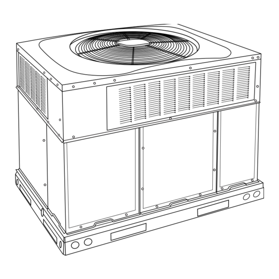
Fig. 1 - Unit 575C
Safety Considerations
This unit is equipped with electrically powered safety measures. For the
safety measures to be effective, the unit must be electrically powered at
all times after installation, other than when servicing.
Manufacturer reserves the right to change, at any time, specifications and designs without notice and without obligations.
Installation Instructions
Improper installation, adjustment, alteration, service maintenance, or use
can cause explosion, fire, electrical shock, or other conditions which
may cause death, personal injury, or property damage. Consult a
qualified installer, service agency, or your distributor or branch for
information or assistance. The qualified installer or agency must use
factory-authorized kits or accessories when modifying this product.
Auxiliary devices which may be a POTENTIAL IGNITION SOURCE
shall not be installed in the duct work. Examples of such POTENTIAL
IGNITION SOURCES are hot surfaces with a temperature exceeding
1292°F (700°C) and electric switching devices.
Electrostatic air purifiers installed in the ductwork are permitted, if the
purifier has an airflow sensor.
False ceilings or drop ceilings must not be used as a return air
A09033
duct/plenum.
Refer to the individual instructions packaged with the kits or accessories
when installing.
This self-contained unit is already charged with refrigerant for optimum
performance, and shouldn't require any adjustments. Should any
installation/service work on the A2L refrigerant system be needed,
non-sparking tools are required. If the refrigerant system is opened, a
refrigerant detector should be used to check for leaks. Open flames or
other ignition sources should not be present, except during brazing.
Brazing should only take place on refrigerant tubes that are open to the
atmosphere or have been properly evacuated.
Follow all safety codes. Wear safety glasses, protective clothing, and
work gloves. Have a fire extinguisher available. Read these instructions
1
WARNING
!
PERSONAL INJURY AND PROPERTY DAMAGE
HAZARD
Continuous fan mode required for proper functioning. Installation must
meet the Required Minimum Dissipation Airflow as outlined in the
Leak Dissipation System section. Follow instructions in the Continuous
Fan Speed Set-Up section to change speeds.
WARNING
!
PERSONAL INJURY AND PROPERTY DAMAGE
HAZARD
For continued performance, reliability, and safety, the only approved
accessories and replacement parts are those specified by the equipment
manufacturer. The use of non-manufacturer approved parts and
accessories could invalidate the equipment limited warranty and result
in fire risk, equipment malfunction, and failure. Please review
manufacturer's instructions and replacement part catalogs available
from your equipment supplier.
Advertisement
Table of Contents

Subscribe to Our Youtube Channel
Related Manuals for Bryant Legacy 575C B Series


Summary of Contents for Bryant Legacy 575C B Series
-
Page 1: Table Of Contents
575C--B Ultra Low NOx: Installation Instructions 575C--B Ultra Low NOx Legacy™ 13.4 SEER2 Single-Packaged Air Conditioner and Gas Furnace System with Puron Advance™ (R-454B) Refrigerant Single Phase 2-5 Nominal Tons (Sizes 24-60) Three Phase 3-5 Nominal Tons (Sizes 36-60) Installation Instructions IMPORTANT: Effective January 1, 2015, all split system and packaged WARNING air conditioners must be installed pursuant to applicable regional... -
Page 2: Introduction
575C--B Ultra Low NOx: Installation Instructions thoroughly and follow all warnings or cautions included in literature and WARNING attached to the unit. consult local building codes, the current editions of the National Fuel Gas Code (NFGC) NFPA 54/ANSI Z223.1, and the PERSONAL INJURY AND PROPERTY DAMAGE National Electrical Code (NEC) NFPA 70. - Page 3 575C--B Ultra Low NOx: Installation Instructions office if any item is missing. To prevent loss or damage, leave all parts in original packages until installation. If the unit is to be mounted on a curb in a downflow application, review OPTIONAL OPTIONAL Step 9...
- Page 4 575C--B Ultra Low NOx: Installation Instructions Step 5 – Rig and Place Unit WARNING WARNING UNIT FALLING HAZARD PERSONAL INJURY OR PROPERTY DAMAGE Failure to follow this warning could result in personal injury or death. HAZARD Never stand beneath rigged units or lift over people. Failure to follow this warning could result in personal injury, death or property damage.
- Page 5 575C--B Ultra Low NOx: Installation Instructions A230476 Fig. 3 – 24-30 Unit Dimensions Manufacturer reserves the right to change, at any time, specifications and designs without notice and without obligations.
- Page 6 575C--B Ultra Low NOx: Installation Instructions A230477 Fig. 4 – 36-60 Unit Dimensions Manufacturer reserves the right to change, at any time, specifications and designs without notice and without obligations.
- Page 7 575C--B Ultra Low NOx: Installation Instructions Dashed lines show cross support location for large basepan units. HVAC unit HVAC unit basepan base rails Sealing Gasket Roofcurb Anchor screw Wood nailer* Flashing field supplied Roofcurb* Insulation (field supplied) Roofing material field supplied Cant strip field supplied A09413...
- Page 8 575C--B Ultra Low NOx: Installation Instructions CAUTION - NOTICE TO RIGGERS PRUDENCE - AVIS AUX MANIPULATEUR ACCESS PANELS MUST BE IN PLACE WHEN RIGGING. PANNEAUX D'ACCES DOIT ÊTRE EN PLACE POUR MANIPULATION. Use top skid as spreader bar. / Utiliser la palette du haut comme barre de répartition DUCTS MINIMUM HEIGHT: 36"...
- Page 9 Table 1 – Physical Data UNIT SIZE 24040 24060 30040 30060 36060 42060 42090 48090 60090 NOMINAL CAPACITY (ton) 2-1/2 2-1/2 3-1/2 3-1/2 SHIPPING WEIGHT lb. SHIPPING WEIGHT (kg) COMPRESSOR / QUANTITY Scroll / 1 REFRIGERANT (R-454B Quantity lb. 5.75 6.25 6.75 8.25...
- Page 10 575C--B Ultra Low NOx: Installation Instructions Table 2 – Maximum Gas Flow Capacity † Length of Pipe ft (m) Nominal Internal Iron Pipe Diameter Size (in.) (in.) (12) (15) (18) (21) (24) (27) (30) (38) (46) (53) (61) .622 — —...
- Page 11 575C--B Ultra Low NOx: Installation Instructions 2. Protect all segments of piping system against physical and thermal WARNING damage. Support all piping with appropriate straps, hangers, etc. Use a minimum of one hanger every 6 ft (1.8 m). For pipe sizes FIRE OR EXPLOSION HAZARD larger than 1/2 in., follow recommendations of national codes.
- Page 12 575C--B Ultra Low NOx: Installation Instructions side tabs. These plastic knockouts are held in place with tabs use vapor barrier in accordance with latest issue of Sheet Metal and similar to an electrical knockout. Discard plastic knockout covers. Air Conditioning Contractors National Association (SMACNA) and Air Conditioning Contractors of America (ACCA) minimum 5.
- Page 13 575C--B Ultra Low NOx: Installation Instructions Standard Connection low-voltage entry points are used (See Fig. 3 Fig. 4 for acceptable location). Run the low-voltage leads from the thermostat, through the inlet hole, NOTE: Field supplied disconnect switch box should be positioned so and into unit low-voltage splice box.
- Page 14 575C--B Ultra Low NOx: Installation Instructions Test Button IMPORTANT: Press the Test Button for approximately ONE SECOND to enter Test Mode. Pressing the Test button for a longer period can possibly clear all fault code history (Table Table 3 – Dissipation Board Test Button Functions Hold Button Time (sec) Function Dissipation Mode for 60 sec...
-
Page 15: Pre-Start-Up
575C--B Ultra Low NOx: Installation Instructions Heat Anticipator Setting (Electro-Mechanical c. Ensure wires do not touch refrigerant tubing or sharp sheet metal edges. Thermostats only) d. Inspect coil fins. If damaged during shipping and handling, The room thermostat heat anticipator must be properly adjusted to carefully straighten fins with a fin comb. - Page 16 575C--B Ultra Low NOx: Installation Instructions 2. If any hot work is to be conducted on the refrigeration system or 16. Conduct follow-up leak test prior to leaving the job site. associated parts, a fire extinguisher shall be available on hand. A Step 2 –...
- Page 17 575C--B Ultra Low NOx: Installation Instructions 5. The evaporator fan will turn on 30 sec. after the flame has been established. The evaporator fan will turn off 90 sec. after the thermostat has been satisfied. Please note that the integrated gas unit controller (IGC) has the capability to automatically reduce the evaporator “ON”...
- Page 18 575C--B Ultra Low NOx: Installation Instructions 4. Turn off gas supply to unit. WARNING 5. Removing manometer from pressure tab. a. For standard gas valve, remove manometer hose and barbed FIRE AND UNIT DAMAGE HAZARD pressure tap. Replace pressure tap cover using an allen wrench. (See Fig.
- Page 19 575C--B Ultra Low NOx: Installation Instructions A240125 Fig. 18 – 208/230-1-60 Ultra Low NOx Connection Wiring Diagram Manufacturer reserves the right to change, at any time, specifications and designs without notice and without obligations.
- Page 20 575C--B Ultra Low NOx: Installation Instructions A240126 Fig. 19 – 208/230-1-60 Ultra Low NOx Ladder Wiring Diagram Manufacturer reserves the right to change, at any time, specifications and designs without notice and without obligations.
- Page 21 575C--B Ultra Low NOx: Installation Instructions A240127 Fig. 20 – 208/230-3-60 Ultra Low NOx Connection Wiring Diagram Manufacturer reserves the right to change, at any time, specifications and designs without notice and without obligations.
- Page 22 575C--B Ultra Low NOx: Installation Instructions A240128 Fig. 21 – 208/230-3-60 Ultra Low NOx Ladder Wiring Diagram Manufacturer reserves the right to change, at any time, specifications and designs without notice and without obligations.
- Page 23 575C--B Ultra Low NOx: Installation Instructions Normal Operation Table 8 – LED Indications An LED (light-emitting diode) indicator is provided on the integrated Status Code LED Indication gas unit controller (IGC) to monitor operation. The IGC is located by Normal Operation removing the control access panel (see Fig.
- Page 24 575C--B Ultra Low NOx: Installation Instructions charge, an R-454B leak detector must be actively monitoring during the 6. Compare actual liquid line temperature with desired liquid line process. temperature. Using a tolerance of ± 2°F (±1.1°C), add refrigerant if actual temperature is more than 2°F (1.1°C) higher than proper WARNING liquid line temperature, or remove refrigerant if actual temperature is more than 2°F (1.1°C) lower than required liquid line...
- Page 25 575C--B Ultra Low NOx: Installation Instructions will deliver the nominal cooling airflow listed in Table 1 for each stops. The unit is in a standby condition, waiting for the next call for size. cooling from the room thermostat. 2. Connect the desired speed tap wire on the “COOL” terminal on the 2-Pin Terminal IGC board.
- Page 26 575C--B Ultra Low NOx: Installation Instructions Table 10 – Cooling Charging Chart Superheat charging table is derived from optimum performance point. (95°F [35°C] outdoor ambient and (80°F [27°C] dry bulb; 67°F [19°C] wet bulb indoor condition.) Where a dash(--) appears do not attempt to check charge or charge unit under these conditions using the superheat method. (Weigh in method should be used.) A240114 A240115 Manufacturer reserves the right to change, at any time, specifications and designs without notice and without obligations.
- Page 27 Table 11 – Dry Coil Air Delivery* - Horizontal and Downflow Discharge Sizes 24-60 Heating ESP (in. W.C.) Unit Allowable Rise Motor Speed Size Functions 0.07 0.08 0.08 0.09 Low† Blue Alternate Heating Gas Heat Rise ( Gas Heat Rise ( 0.12 0.13 0.13...
- Page 28 Table 11 – Dry Coil Air Delivery* - Horizontal and Downflow Discharge Sizes 24-60 Heating ESP (in. W.C.) Unit Allowable Rise Motor Speed Size Functions 0.09 0.10 0.11 0.11 0.11 Low† Blue Alternate Heating Gas Heat Rise ( Gas Heat Rise ( 0.14 0.15 0.15...
- Page 29 Table 11 – Dry Coil Air Delivery* - Horizontal and Downflow Discharge Sizes 24-60 Heating ESP (in. W.C.) Unit Allowable Rise Motor Speed Size Functions 1096 1044 0.14 0.15 0.16 0.18 0.19 0.19 0.20 0.21 0.22 0.23 Alternate Cooling, Low† Blue Alternate Heating Gas Heat Rise (...
- Page 30 Table 11 – Dry Coil Air Delivery* - Horizontal and Downflow Discharge Sizes 24-60 Heating ESP (in. W.C.) Unit Allowable Rise Motor Speed Size Functions 0.13 0.13 0.14 0.15 0.16 0.16 0.17 0.18 0.18 0.19 Low† Blue Gas Heat Rise ( Gas Heat Rise ( 1201 1153...
- Page 31 Table 11 – Dry Coil Air Delivery* - Horizontal and Downflow Discharge Sizes 24-60 Heating ESP (in. W.C.) Unit Allowable Rise Motor Speed Size Functions 0.05 0.06 0.06 0.07 0.07 0.08 0.08 0.09 Low† Blue Gas Heat Rise ( Gas Heat Rise ( 1437 1395 1351...
-
Page 32: Maintenance
575C--B Ultra Low NOx: Installation Instructions Table 14 – Filter Pressure Drop Table (IN. W.C.) Cooling Standard CFM (SCFM) Filter Size in. (mm) Tons 600 700 800 900 1000 1100 1200 1300 1400 1500 1600 1700 1800 1900 2000 2100 2200 600-1400 CFM 2.0, 12x20x1+12x20x1... - Page 33 575C--B Ultra Low NOx: Installation Instructions a. Ensure proper reassembly by marking wheel orientation. If lockout occurs, unit may be reset by either momentarily interrupting b. Lift wheel from housing. When handling and/or cleaning blower power supply to unit or by turning selector switch to OFF position at the wheel, be sure not to disturb balance weights (clips) on blower thermostat.
- Page 34 575C--B Ultra Low NOx: Installation Instructions done by removing the screws from the front cover of the burner box and losing the screws on each side of the top cover to allow easy removal of baffle from the burner box. Once the baffle is removed the inlet side of the burner can be accessed and cleaned.
- Page 35 575C--B Ultra Low NOx: Installation Instructions FAN GRILLE MOTOR MOTOR SHAFT A08505 MAX DISTANCE BETWEEN TOP OF FAN GRILLE AND BOTTOM OF FAN BLADE “A” Size Fig. 27 – Fan Blade Position Electrical Controls and Wiring not be used.If a refrigerant leak is detected, refer to the Check for Refrigerant Leaks section.
-
Page 36: Troubleshooting
575C--B Ultra Low NOx: Installation Instructions Servicing Systems on Roofs with Synthetic Materials pressure gauges read 0 psig. Never open system without breaking vacuum with dry nitrogen. POE (polyolester) compressor lubricants are known to cause long term High-Pressure Switch damage to some synthetic roofing materials. The high-pressure switch is located in the discharge line and protects Exposure, even if immediately cleaned up, may cause embrittlement against excessive condenser coil pressure. -
Page 37: Start-Up Checklist
575C--B Ultra Low NOx: Installation Instructions Flashing 2 Check both ends of the sensor wire harness to ensure proper attachment. Power cycle the system to check whether the flash code has been removed. If the flash code is still present, replace the sensor. Flashing 3 Check for refrigerant leaks using an independent R-454B detector. - Page 38 575C--B Ultra Low NOx: Installation Instructions Table 15 – Troubleshooting Chart SYMPTOM CAUSE REMEDY Power failure Call power company Fuse blown or circuit breaker tripped Replace fuse or reset circuit breaker Defective contactor, transformer, or high-pressure, Replace component loss-of-charge or low-pressure switch Compressor and condenser fan will not start.
- Page 39 575C--B Ultra Low NOx: Installation Instructions Table 16 – Troubleshooting Guide–Heating SYMPTOM CAUSE REMEDY Water in gas line Drain. Install drip leg. No power to furnace Check power supply fuses, wiring or circuit breaker. Check transformer. No 24-v power supply to control circuit NOTE: Some transformers have internal over-current protection that requires a cool-down period to reset.
- Page 40 575C--B Ultra Low NOx: Installation Instructions Table 18 – Troubleshooting Guide–LED Status Codes SYMPTOM CAUSE REMEDY Check 5-amp fuse son IGC*, power to unit, 24-v circuit breaker, No Power or Hardware failure and transformer. Units without a 24-v circuit breaker have an Loss of power to control module (IGC)*.
- Page 41 575C--B Ultra Low NOx: Installation Instructions Start-Up Checklist (Remove and Store in Job Files) I. PRELIMINARY INFORMATION MODEL NO.: ____________________________________________ SERIAL NO.: ____________________________________________ DATE: __________________________________________________ TECHNICIAN: ___________________________________________ II. PRESTART-UP (Insert check mark in box as each item is completed) (¦ ) VERIFY THAT ALL PACKING MATERIALS HAVE BEEN REMOVED FROM UNIT ( ) REMOVE ALL SHIPPING HOLD DOWN BOLTS AND BRACKETS PER INSTALLATION INSTRUCTIONS ( ) CHECK ALL ELECTRICAL CONNECTIONS AND TERMINALS FOR TIGHTNESS ( ) CHECK GAS PIPING FOR LEAKS (WHERE APPLICABLE)
- Page 42 575C--B Ultra Low NOx: Installation Instructions Decommissioning i. Record the amount of R-454B refrigerant recovered and note on the logs of each cylinder used. This unit is designed to provide many years of comfort. Eventually, this j. Cut out the form below and fill out, sign, and date. Affix the form unit will need to be replaced.
Need help?
Do you have a question about the Legacy 575C B Series and is the answer not in the manual?
Questions and answers