Bryant 577C Installation Instructions Manual
Preferred 14 seer single--packaged air conditionerand gas furnace system with puron (r--410a) refrigerant single and three phase 1-1/2-5 nominal tons (sizes 018--060)
Hide thumbs
Also See for 577C:
- Installation instructions manual (60 pages) ,
- Owner's information manual (10 pages) ,
- Installation instructions manual (36 pages)
Table of Contents
Advertisement
577C
PREFERRED
14 SEER SINGLE- - PACKAGED AIR CONDITIONER
t
AND GAS FURNACE SYSTEM WITH PURONr (R- - 410A) REFRIGERANT
SINGLE AND THREE PHASE
1- - 1/2 - - 5 NOMINAL TONS (SIZES 018- - 060)
NOTE:
Read the entire instruction manual before starting the
installation.
NOTE:
Installer: Make sure the Owner's Manual and Service
Instructions are left with the unit after installation.
TABLE OF CONTENTS
. . . . . . . . . . . . . . . . . . . . . . . . . . . . . . . . . . .
. . . . . . . . . . . . . . . . . . . . . . . . . . . . . . . . . .
. . . . . . . . . . . . . . . . . . . . . . . . . . . . . . . . . . . .
. . . . . . . . . . . . . . . . . . . . . . . . . . . . . . . . .
. . . . . . . . . . . . . . . . . . . . . . . . . . . . . . .
. . . . . . . . . . . . . . . . . . . . . . . . . . . . . . . . . . . . . .
. . . . . . . . . . . . . . . . . . . . . . . . . . . . . . . . . . . . .
. . . . . . . . . . . . . . . . . . . . . . . . . . . . . . . . . .
. . . . . . . . . . . . . . . . . . . . . . . . . . . .
. . . . . . . . . . . . . . . . . . . . . . . . . . . . . . . . .
. . . . . . . . . . . . . . . . . . . . . . . . . . . . . . . . .
. . . . . . . . . . . . . . . . . . . . . . . . . . . . . . . . . . . . . .
. . . . . . . . . . . . . . . . . . . . . . . . . . . .
. . . . . . . . . . . . . . . . . . . . . . . . . . . . . . . . . .
. . . . . . . . . . . . . . . . . . . . . . . . . . . . . . . . . . .
. . . . . . . . . . . . . . . . . . . . . . . . . . . . . . . . . .
. . . . . . . . . . . . . . . . . . . . . . . . . . . . .
. . . . . . . . . . . . . . . . . . . . . . . . . . . . . . . . . . .
. . . . . . . . . . . . . . . . . . . . . . . . . . . . .
. . . . . . . . . . . . . . . . . . . . . . . . . . .
. . . . . . . . . . . . . . . . . . . . . . . . . . . . . . . .
. . . . . . . . . . . . . . . . . . . . . . . . . . . . . . . . . . . . .
. . . . . . . . . . . . . . . . . . . . . . . . . . .
. . . . . . . . . . . . . . . . . . . . . . . . . . . . . . . .
. . . . . . . . . . . . . . . . . . . . . . . . . . . . . . . .
. . . . . . . . . . . . . . . . . . . . . . . . . . . . .
. . . . . . . . . . . . . . . . . . . . . . . . . . . . . . . . .
. . . . . . . . . . . . . . . . . . . . . . . . . . . . . . . . .
Installation Instructions
. . . . . . . . . . . . . . . . . . . . . . . . .
. . . . . . . . . . . . . . . . .
. . . . . . . . . . . . . . . . . . . . . . . . . . .
. . . . . . . . . . . . . . . . . . . . . . . .
. . . . . . . . . . . . . . . . . . . . . . . .
. . . . . . . . . . . . . .
. . . . . . . . . . . . . . . . . . . . . . .
. . . . . . . . . . . . . . . . . . . . . . . . . .
. . . . . . . . . . . . . . . . . . . . . . . . .
. . . . . . . . . . . . . . . .
. . . . . . . . . . . . . . . . . . . . . .
. . . . . . . . . . . . . . . . . . . . .
. . . . . . . . . . . . . . . .
. . . . . . . . . . . . . . . .
. . . . . . . . . . . .
. . . . . . . . . . . . .
. . . . . . . . . . . . . . . . . . . . .
PAGE
1
2
2- -12
2
2
2
2
2
2
2
2
6
6
6
6
6
8
. . . . . . . . . . . . . . . . . . . . . . . . . . . . . . . . . . . . . .
8
8
9
9- -10
11
11
11
11
11
12
12
. . . . . . . . . . . . . . . . . . . . . . . . . . . . . . . . . . . . . .
12- -13
13- -20
13
13
13
SAFETY CONSIDERATIONS
14
14
Installation and servicing of this equipment can be hazardous due
15
to mechanical and electrical components. Only trained and
15
qualified personnel should install, repair, or service this equipment.
15
Untrained personnel can perform basic maintenance functions such
19
as cleaning and replacing air filters. All other operations must be
19
performed by trained service personnel. When working on this
19
equipment, observe precautions in the literature, on tags, and on
19
labels attached to or shipped with the unit and other safety
19
precautions that may apply.
20
Follow all safety codes. Installation must be in compliance with
20
local and national building codes. Wear safety glasses, protective
clothing, and work gloves. Have fire extinguisher available. Read
these instructions thoroughly and follow all warnings or cautions
included in literature and attached to the unit.
Recognize safety information. This is the safety- -alert symbol
When you see this symbol on the unit and in instructions or manu-
1
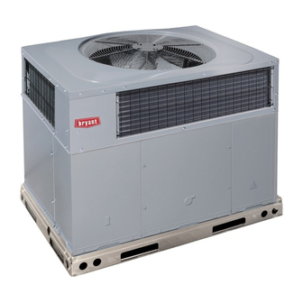
Fig. 1 - - Unit 577C
(Low NOx Model Available)
. . . . . . . . . . . . . . . . . . . . . . . . . . . . . . . .
. . . . . . . . . . . . . . . . . . . . . . . . .
. . . . . . . . . . . . . .
. . . . . . . . . . . . . . . . . . . . . . . . . . . .
. . . . . . . . . . . . . . . . . . . . . . . . . . . . . . . . . . .
. . . . . . . . . . . . . . . . . . . . . . . . . . . . . . . . .
. . . . . . . . . . . . . . . . . . . . . . . . . . . . . . . . . . .
. . . . . . . . . . . . . . . . . . . . . . . . . . . .
. . . . . . . . . . . . . . . . . . . . . . . . . . . . . . . . . . .
. . . . . . . . . . . . . . . . . . . . .
. . . . . . . . . . . . . . . . . . . . . . . . . . . . . . .
. . . . . . . . . . . . . . . . . . . . . . . . . . . . . .
. . . . . . . . . . . . . . . . . . . . . . . . . . . . . . . . . . . .
. . . . . . . . . . . . . . . . . . . . . . . . . . . . . .
. . . . . . . . . . . . . . . . . . . . . . . . . . . .
A99338
27- -30
28
28
28
28
28
28
28
28
. . . .
29
29
29
30
30
30
30
31
31
.
Advertisement
Table of Contents

Related Manuals for Bryant 577C


Summary of Contents for Bryant 577C
-
Page 1: Table Of Contents
........Fig. 1 - - Unit 577C Use of Rigging Bracket . -
Page 2: Introduction
RETURN SUPPLY OPENING OPENING INTRODUCTION The 577C unit (see Fig. 1) is a fully self- -contained, combination Category I gas heating/electric cooling unit designed for outdoor 2˝ (50.8mm) installation (See Fig. 3 and 4 for unit dimensions). All unit sizes... - Page 3 A08058 Fig. 3 - - 577C018- -036 Unit Dimensions...
- Page 4 A08059 Fig. 4 - - 577C042- -060 Unit Dimensions...
- Page 5 HVAC unit HVAC unit base base Gask eting inner flange* Scre w Scre w Gask eting (NO TE A) (NO TE A) inner flange* *Gask eting *Gask eting outer flange outer flange Wood nailer* Wood nailer* Flashing field Flashing field supplied supplied Roof curb*...
-
Page 6: Provide Clearances
Step 4 — Provide Clearances WARNING The required minimum operating and service clearances are shown in Fig. 3 and 4. Adequate combustion, ventilation and condenser PROPERTY DAMAGE HAZARD air must be provided. Failure to follow this warning could result in personal IMPORTANT: Do not restrict outdoor airflow. - Page 7 Table 1 – Physical Data - - Unit 577C UNIT SIZE 018040 024040 024060 030040 030060 036060 036090 042060 042090 NOMINAL CAPACITY (ton) 1--- 1/2 2--- 1/2 2--- 1/2 3--- 1/2 3--- 1/2 SHIPPING WEIGHT** lb. SHIPPING WEIGHT** (kg) 158.8 163.7...
-
Page 8: Connect Condensate Drain
NOTE: Low NOx requirements apply only to natural gas Model 577C disposes of condensate water through a 3/4 in. NPT installations. fitting which exits through the base on the evaporator coil access side. See Fig. 3 & 4 for location. -
Page 9: Install Duct Connections
For natural gas applications, the gas pressure at unit gas connection NOTE: Pressure test the gas supply system after the gas supply must not be less than 4.0 in. wc or greater than 13 in. wc while the piping is connected to the gas valve. The supply piping must be unit is operating. - Page 10 Table 2 – Maximum Gas Flow Capacity* LENGTH OF PIPE FT (m)† NOMINAL INTERNAL IRON PIPE DIAMETER SIZE (IN.) (IN.) (12) (15) (18) (21) (24) (27) (30) (38) (46) (53) (61) .622 — — (53) (37) (30) (25) (22) (20) (19) (17) (16)
-
Page 11: Install Electrical Connections
High- - Voltage Connections screwed or bolted to duct flanges. Use suitable gaskets to ensure weather- -tight and airtight seal. When routing power leads into unit, use only copper wire between 4. All units must have field- -supplied filters or accessory filter disconnect and unit. -
Page 12: Standard Connection
Control Voltage Connections PRE- - START- - UP Do not use any type of power- -stealing thermostat. Unit control WARNING problems may result. Use no. 18 American Wire Gage (AWG) color- -coded, insulated (35_C minimum) wires to make the control voltage connections ENVIRONMENTAL, FIRE, EXPLOSION,... -
Page 13: Check For Refrigerant Leaks
WARNING FIRE, EXPLOSION HAZARD Failure to follow this warning could result in personal injury, death or property damage. Do not purge gas supply into the combustion chamber. Do not use a match or other open flame to check for gas leaks. 4. -
Page 14: Check Gas Input
Check Gas Input Adjust Gas Input Check gas input and manifold pressure after unit start- -up (See The gas input to the unit is determined by measuring the gas flow Table 4). If adjustment is required proceed as follows: at the meter or by measuring the manifold pressure. Measuring the gas flow at the meter is recommended for natural gas units. -
Page 15: Check Burner Flame
Normal Operation decrease input (See Fig. 14). Manifold pressure must be between 3.2 and 3.8 IN. WC. An LED (light- -emitting diode) indicator is provided on the integrated gas unit controller (IGC) to monitor operation. The IGC WARNING is located by removing the burner access panel. During normal operation, the LED is continuously on (See Table 5 for error codes). - Page 16 A08052 Fig. 15 - - 208/230- -1- -60 Wiring Diagram...
- Page 17 A08053 Fig. 16 - - 208/230- -3- -60 Wiring Diagram...
- Page 18 A08010 Fig. 17 - - 460- -3- -60 Wiring Diagram...
-
Page 19: Limit Switches
Limit Switches Observe that unit operates in Heating mode when temperature control is set to call for heating (above room Normally closed limit switch (LS) completes the control circuit. temperature) and operates in Cooling mode when Should the leaving- -air temperature rise above the maximum temperature control is set to call for cooling (below room allowable temperature, the limit switch opens and the control temperature). -
Page 20: Indoor Airflow And Airflow Adjustments
NOTE: If the problem causing the inaccurate readings is a refrigerant leak, refer to the Check for Refrigerant Leaks section. Indoor Airflow and Airflow Adjustments CAUTION UNIT OPERATION HAZARD Failure to follow this caution may result in unit damage. For cooling operation, the recommended airflow is 350 to 450 cfm for each 12,000 Btuh of rated cooling capacity. - Page 21 Table 7 – Cooling Charging Chart A07626...
- Page 22 Table 8 – Filter Pressure Drop Table (IN. W.C.) FILTER SIZE in. (mm) 900 1000 1100 1200 1300 1400 1500 1600 1700 1800 1900 2000 2100 2200 2300 20X20X1 0.05 0.07 0.08 0.12 0.13 0.14 0.15 — — — — —...
- Page 23 Table 9 — Dry Coil Air Delivery* - - Horizontal and Downflow Discharge - - Unit 577C018- -060 (Cont) HEATING EXTERNAL STATIC PRESSURE (”WC) MOTOR WIRE UNIT RISE SPEED COLOR RANGE --- --- --- --- --- --- --- --- --- --- Heating Rise Blue Heating Rise...
- Page 24 Table 9 — Dry Coil Air Delivery* - - Horizontal and Downflow Discharge - - Unit 577C018- -060 (Cont) HEATING EXTERNAL STATIC PRESSURE (”WC) MOTOR WIRE UNIT RISE SPEED COLOR RANGE 1206 1151 1085 1033 Heating Rise Blue Heating Rise 1369 1317 1262...
- Page 25 Table 9 — Dry Coil Air Delivery* - - Horizontal and Downflow Discharge - - Unit 577C018- -060 (Cont) HEATING EXTERNAL STATIC PRESSURE (”WC) MOTOR WIRE UNIT RISE SPEED COLOR RANGE 1295 1234 1182 1126 1075 1016 Heating Rise Blue Heating Rise 1345 1282...
- Page 26 Table 9 — Dry Coil Air Delivery* - - Horizontal and Downflow Discharge - - Unit 577C018- -060 (Cont) HEATING EXTERNAL STATIC PRESSURE (”WC) MOTOR WIRE UNIT RISE SPEED COLOR RANGE 1445 1389 1341 1281 1236 1189 1139 1072 1027 Heating Rise Blue Heating Rise...
-
Page 27: Maintenance
High Black Heating Rise * Air delivery values are without air filter and are for dry coil (See Table 10 --- 577C Wet Coil Pressure Drop table). Factory ---shipped heating speed Factory ---shipped cooling speed NA --- Not allowed for heating speed Note: Deduct field---supplied air filter pressure drop and wet coil pressure drop to obtain external static pressure available for ducting. -
Page 28: Air Filter
2. Inspect indoor coil, drain pan, and condensate drain each brush attachment. Remove grease and oil with mild cooling season for cleanliness. Clean when necessary. solvent. 3. Inspect blower motor and wheel for cleanliness at the d. Reassemble wheel into housing. beginning of each heating and cooling season. -
Page 29: Outdoor Coil, Indoor Coil, & Condensate Drain Pan
4. Disconnect gas piping at unit gas valve. 5. Remove wires connected to gas valve. Mark each wire. BLOWER 6. Remove ignitor and sensor wires at the ignitor module. HOUSING 7. Remove the mounting screw that attaches the burner rack to the unit base (See Fig. -
Page 30: Refrigerant Circuit
1. Turn off all power to unit. Refrigerant System 2. Disconnect leads on switch. This information covers the refrigerant system of the 577C, 3. Apply ohm meter leads across switch. You should have including the compressor oil needed, servicing systems on roofs continuity on a good switch. -
Page 31: Troubleshooting
Liquid Line Filter Drier Compressor Oil The Copeland scroll compressor uses Mobil 3MAF POE oil. This filter drier is specifically designed to operate with Puron. Use Copeland Ultra 22 CC should be used if additional oil is needed in only factory- -authorized components. Filter drier must be replaced the field. - Page 32 PURONR (R- -410A) QUICK REFERENCE GUIDE S Puron refrigerant operates at 50- -70 percent higher pressures than R- -22. Be sure that servicing equipment and replacement components are designed to operate with Puron S Puron refrigerant cylinders are rose colored. S Recovery cylinder service pressure rating must be 400 psig, DOT 4BA400 or DOT BW400.
- Page 33 Table 11 – Troubleshooting Chart SYMPTOM CAUSE REMEDY Power failure Call power company Fuse blown or circuit breaker tripped Replace fuse or reset circuit breaker Defective contactor, transformer, or high--pressure, Replace component loss--of--charge or low--pressure switch Compressor and condenser fan will not start. Insufficient line voltage Determine cause and correct Incorrect or faulty wiring...
- Page 34 Table 12 – Troubleshooting Guide–Heating SYMPTOM CAUSE REMEDY Water in gas line Drain. Install drip leg. No power to furnace Check power supply fuses, wiring or circuit breaker. Check transformer. No 24--v power supply to control circuit NOTE: Some transformers have internal over--current protection that requires a cool--down period to reset.
- Page 35 START-UP CHECKLIST (Remove and Store in Job File) I. Preliminary Information MODEL NO.:_________________________________ SERIAL NO.:__________________________________ DATE:_______________________________________ TECHNICIAN:_________________________________ II. PRE-START-UP (Insert checkmark in box as each item is completed) ( ) VERIFY THAT ALL PACKING MATERIALS HAVE BEEN REMOVED FROM UNIT ( ) REMOVE ALL SHIPPING HOLD DOWN BOLTS AND BRACKETS PER INSTALLATION INSTRUCTIONS ( ) CHECK ALL ELECTRICAL CONNECTIONS AND TERMINALS FOR TIGHTNESS ( ) CHECK GAS PIPING FOR LEAKS (WHERE APPLICABLE)
- Page 36 Catalog No. II577C ---02 E2008 Bryant Heating & Cooling Systems D 7310 W. Morris St. D Indianapolis, IN 46231 Printed in U.S.A. Edition Date: 02/08 Manufacturer reserves the right to discontinue, or change at any time, specifications or designs without notice and without incurring obligations.
Need help?
Do you have a question about the 577C and is the answer not in the manual?
Questions and answers