Bryant LEGACY 574D A Series Installation Instructions Manual
13 seer single-packaged air conditioner and gas furnace system with puron(r-410a) refrigerant
Hide thumbs
Also See for LEGACY 574D A Series:
- Owner's information manual (10 pages) ,
- Product data (57 pages) ,
- Installation instructions manual (60 pages)
Table of Contents
Advertisement
Quick Links
574D- -- -A
LEGACYt 13 SEER SINGLE- -PACKAGED AIR CONDITIONER AND
GAS FURNACE SYSTEM WITH PURONR (R- -410A) REFRIGERANT
SINGLE AND THREE PHASE
2- -5 NOMINAL TONS (SIZES 24- -60)
NOTE:
Read the entire instruction manual before starting the
installation.
NOTE:
Installer: Make sure the Owner's Manual and Service
Instructions are left with the unit after installation.
TABLE OF CONTENTS
. . . . . . . . . . . . . . . . . . . . . . . . . . . . . . . . . . .
. . . . . . . . . . . . . . . . . . . . . . . . . . . . . . . . . .
. . . . . . . . . . . . . . . . . . . . . . . . . . . . . . . . . . . .
. . . . . . . . . . . . . . . . . . . . . . . . . . . . . . . . .
. . . . . . . . . . . . . . . . . . . . . . . . . . . . . . .
. . . . . . . . . . . . . . . . . . . . . . . . . . . . . . . . . . . . . .
. . . . . . . . . . . . . . . . . . . . . . . . . . . . . . . . . . . . .
. . . . . . . . . . . . . . . . . . . . . . . . . . . .
. . . . . . . . . . . . . . . . . . . . . . . . . . . . . . . . .
. . . . . . . . . . . . . . . . . . . . . . . . . . . . . . . . .
. . . . . . . . . . . . . . . . . . . . . . . . . . . . . . . . . . . . . .
. . . . . . . . . . . . . . . . . . . . . . . . . . . . . . . . . .
. . . . . . . . . . . . . . . . . . . . . . . . . . . . . . . . . . .
. . . . . . . . . . . . . . . . . . . . . . . . . . . . . . . . . .
. . . . . . . . . . . . . . . . . . . . . . . . . . . .
. . . . . . . . . . . . . . . . . . . . . . . . . . . . . . . . . . . . .
. . . . . . . . . . . . . . . . . . . . . . . . . . . . .
. . . . . . . . . . . . . . . . . . . . . . . . . . .
. . . . . . . . . . . . . . . . . . . . . . . . . . . . . . . . . . .
. . . . . . . . . . . . . . . . . . . . . . . . . . . . . . . . . . . . .
. . . . . . . . . . . . . . . . . . . . . . . . . . .
. . . . . . . . . . . . . . . . . . . . . . . . . . . . . . . .
. . . . . . . . . . . . . . . . . . . . . . . . . . . . . . . .
. . . . . . . . . . . . . . . . . . . . . . . . . . . . .
. . . . . . . . . . . . . . . . . . . . . . . . . . . . . . .
. . . . . . . . . . . . . . . . . . . . . . . . . . . . . . . . .
. . . . . . . . . . . . . . . . . . . . . . . . . . . . . . . . .
MAINTENANCE
. . . . . . . . . . . . . . . . . . . . . . . . . . . . . . . .
Air Filter
. . . . . . . . . . . . . . . . . . . . . . . . . . . . . . . . . . . . . .
Installation Instructions
. . . . . . . . . . . . . . . . . . . . . . . . .
. . . . . . . . . . . . . . . . .
. . . . . . . . . . . . . . . . . . . . . . . . . . .
. . . . . . . . . . . . . . . . . . . . . . . .
. . . . . . . . . . . . . . . . . . . . . . . .
. . . . . . . . . . . . . .
. . . . . . . . . . . . . . . . . . . . . . .
. . . . . . . . . . . . . . . . . . . . . . . . . .
. . . . . . . . . . . . . . . . . . . . . . . . .
. . . . . . . . . . . . . . . .
. . . . . . . . . . . . . . . . . . . . . .
. . . . . . . . . . . . . . . . . . . . .
. . . . . . . . . . . . . . . .
. . . . . . . . . . . . . . . .
. . . . . . . . . . . .
. . . . . . . . . . . . .
. . . . . . . . . . . . . . . . . . . . . . . .
. . . . . . . . . . . . . . . . . . . . .
PAGE
1
2
2- -13
2
2
2
2
2
2
6
6
6
6
Indoor Blower and Motor
6
Induced Draft (Combustion Air) Blower
9
Flue Gas Passageways
9
Limit Switch
9
Burner Ignition
10
Main Burners
Removal of Gas Train
10
Outdoor Coil, Indoor Coil, & Condensate Drain Pan
12
Outdoor Fan
12
Electrical Controls and Wiring
12
Refrigerant Circuit
12
Gas Input
. . . . . . . . . . . . . . . . . . . . . . . . . . . . . . . . . . . . . .
12
Evaporator Airflow
13
Puron Items
13
TROUBLESHOOTING
13
START- -UP CHECKLIST
14- -22
SAFETY CONSIDERATIONS
14
Improper installation, adjustment, alteration, service maintenance,
14
or use can cause explosion, fire, electrical shock, or other
14
conditions which may cause death, personal injury, or property
14
damage. Consult a qualified installer, service agency, or your
15
distributor or branch for information or assistance. The qualified
16
installer or agency must use factory- -authorized kits or accessories
20
when modifying this product. Refer to the individual instructions
20
packaged with the kits or accessories when installing.
20
20
Follow all safety codes. Wear safety glasses, protective clothing,
20
and work gloves. Have a fire extinguisher available. Read these
20
instructions thoroughly and follow all warnings or cautions
20
included in literature and attached to the unit. Consult local
20
building codes, the current editions of the National Fuel Gas Code
21
(NFGC) NFPA 54/ANSI Z223.1, and the National Electrical Code
21
(NEC) NFPA 70.
22
In Canada refer to the current editions of the National Standards of
29- -30
Canada CAN/CSA- -B149.1 and .2 Natural Gas and Propane
29
Installation codes, and Canadian Electrical Code CSA C22.1
Recognize safety information. This is the safety- -alert symbol
When you see this symbol on the unit and in instructions or manu-
als, be alert to the potential for personal injury. Understand these
signal words: DANGER, WARNING, and CAUTION. These
1
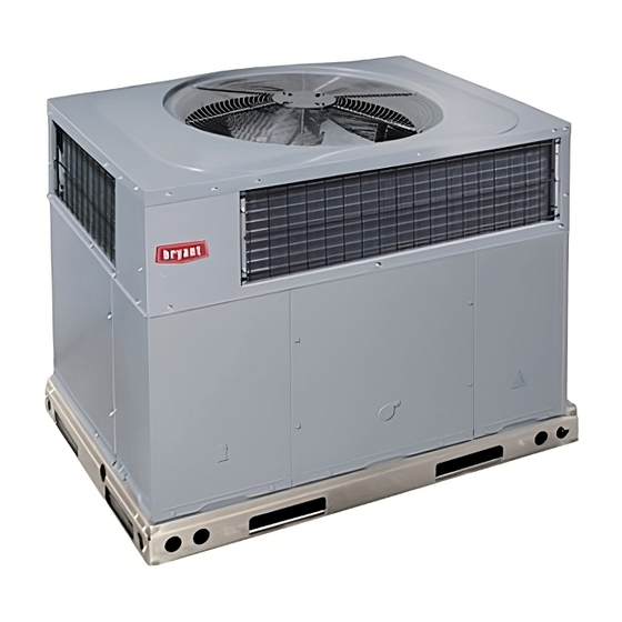
Fig. 1 - - Unit 574D- -- -A
(Low NOx Model Available)
. . . . . . . . . . . . . . . . . . . . . . . . .
. . . . . . . . . . . . . .
. . . . . . . . . . . . . . . . . . . . . . . . . . . .
. . . . . . . . . . . . . . . . . . . . . . . . . . . . . . . . . . .
. . . . . . . . . . . . . . . . . . . . . . . . . . . . . . . . .
. . . . . . . . . . . . . . . . . . . . . . . . . . . . . . . . . . .
. . . . . . . . . . . . . . . . . . . . . . . . . . . .
. . . . . . . . . . . . . . . . . . . . . . . . . . . . . . . . . . .
. . . . . . . . . . . . . . . . . . . . .
. . . . . . . . . . . . . . . . . . . . . . . . . . . . . . .
. . . . . . . . . . . . . . . . . . . . . . . . . . . . . .
. . . . . . . . . . . . . . . . . . . . . . . . . . . . . . . . . . . .
. . . . . . . . . . . . . . . . . . . . . . . . . . . . . .
. . . . . . . . . . . . . . . . . . . . . . . . . . . .
A09034
29
30
30
30
30
30
30
. . . .
30
31
32
32
32
32
32
33
33
.
Advertisement
Table of Contents

Related Manuals for Bryant LEGACY 574D A Series


Summary of Contents for Bryant LEGACY 574D A Series
-
Page 1: Table Of Contents
574D- -- -A LEGACYt 13 SEER SINGLE- -PACKAGED AIR CONDITIONER AND GAS FURNACE SYSTEM WITH PURONR (R- -410A) REFRIGERANT SINGLE AND THREE PHASE 2- -5 NOMINAL TONS (SIZES 24- -60) Installation Instructions NOTE: Read the entire instruction manual before starting the installation. -
Page 2: 574D
words are used with the safety- -alert symbol. DANGER identifies have it examined by transportation inspectors before removal. the most serious hazards which will result in severe personal injury Forward claim papers directly to transportation company. or death. WARNING signifies hazards which could result in per- Manufacturer is not responsible for any damage incurred in transit. - Page 3 A09469 Fig. 2 - - 574D- -- -A24- -36 Unit Dimensions...
- Page 4 A09470 Fig. 3 - - 574D- -- -A42- -60 Unit Dimensions...
- Page 5 Dashed lines show cross support location for large basepan units. HVAC unit HVAC unit basepan base rails Sealing Gasket Roofcurb Anchor screw Wood nailer* Flashing field supplied Roofcurb* Insulation (field supplied) Roofing material field supplied Cant strip field supplied SMALL/COMMON CURB A09413 *Provided with roofcurb A09090...
-
Page 6: Field Fabricate Ductwork
Training for operators of the lifting equipment should include, but not be limited to, the following: 1. Application of the lifter to the load, and adjustment of the OPTIONAL OPTIONAL RETURN SUPPLY lifts to adapt to various sizes or kinds of loads. OPENING OPENING 2. - Page 7 CAUTION - NOTICE TO RIGGERS PRUDENCE - AVIS AUX MANIPULATEUR ACCESS PANELS MUST BE IN PLACE WHEN RIGGING. PANNEAUX D'ACCES DOIT ÊTRE EN PLACE POUR MANIPULATION. Use top skid as spreader bar. / Utiliser la palette du haut comme barre de répartition DUCTS MINIMUM HEIGHT: 36"...
- Page 8 Table 1 – Physical Data - - Unit 574D- -- -A UNIT SIZE 24040 24060 30040 30060 36060 36090 42060 42090 NOMINAL CAPACITY (ton) 2 ---1/2 2 ---1/2 3 ---1/2 3 ---1/2 SHIPPING WEIGHT** lb. SHIPPING WEIGHT** (kg) Scroll COMPRESSORS Quantity REFRIGERANT (R --- 410A) Quantity lb.
-
Page 9: Connect Condensate Drain
Step 6 — Connect Condensate Drain 3. Secure flue hood to flue panel by inserting a single screw on the top flange and the bottom flange of the hood. NOTE: When installing condensate drain connection be sure to Step 8 — Install Gas Piping comply with local codes and restrictions. -
Page 10: Install Duct Connections
Table 2 – Maximum Gas Flow Capacity* LENGTH OF PIPE FT (m)† NOMINAL INTERNAL IRON PIPE DIAMETER SIZE (IN.) (IN.) (12) (15) (18) (21) (24) (27) (30) (38) (46) (53) (61) .622 — — .824 1.049 1--- 1/4 1.380 1400 1--- 1/2 1.610 2100... - Page 11 NOTE: On large chassis units remove sheet metal shields on panels by using a screw driver to shear off retainers and discard. CAUTION UNIT COMPONENT DAMAGE HAZARD Failure to follow this caution may result in damage to the unit being installed. When cutting duct panels, do not contact or damage any internal components (heat exchanger, electric heat).
-
Page 12: Install Electrical Connections
heating and air conditioning systems. Secure all ducts to Single phase units: building structure. 1. Run the high- -voltage (L1, L2) and ground lead into the 7. Flash, weatherproof, and vibration isolate all openings in control box. building structure in accordance with local codes and good 2. -
Page 13: Heat Anticipator Setting
PRE- - START- - UP connections (See Fig. 11). Secure all cut wires, so that they do not interfere with operation of unit. WARNING HIGH VOLTAGE ENVIRONMENTAL, FIRE, EXPLOSION, POWER LEADS POWER (SEE UNIT WIRING SUPPLY ELECTRICAL SHOCK HAZARD LABEL) 3-PHASE SHOWN Failure to follow this warning could result in personal 1-PHASE USES... -
Page 14: Check For Refrigerant Leaks
WARNING FIRE, EXPLOSION HAZARD Failure to follow this warning could result in personal injury, death or property damage. Do not purge gas supply into the combustion chamber. Do not use a match or other open flame to check for gas leaks. Use a commercially available soap solution made specifically for the detection of leaks to check all connections. -
Page 15: Adjust Gas Input
IN THE U.S.A.: REGULATOR COVER SCREW The input rating for altitudes above 2,000 ft (610 m) must be PLASTIC reduced by 4% for each 1,000 ft (305 m) above sea level. ADJUSTMENT SCREW For installations below 2,000 ft (610 m), refer to the unit rating ON/OFF SWITCH plate. -
Page 16: Check Burner Flame
4. Turn off gas supply to unit. Remove manometer from above 2,000 ft (610 m), contact your distributor for proper propane pressure tap and replace pipe plug on gas valve. (See Fig. conversion kit. 12.) Turn on gas to unit and check for leaks. Check Burner Flame Measure Manifold Pressure (Propane Units) With control access panel (see Fig. - Page 17 A09282 Fig. 15 - - 208/230- -1- -60 Wiring Diagram...
- Page 18 A09264 Fig. 16 - - 208/230- -3- -60 Wiring Diagram...
- Page 19 A09265 Fig. 17 - - 460- -3- -60 Wiring Diagram...
-
Page 20: Normal Operation
Normal Operation burners. When the temperature at the rollout switch reaches the maximum allowable temperature, the control circuit trips, closing An LED (light- -emitting diode) indicator is provided on the the gas valve and stopping gas flow to the burners. The indoor integrated gas unit controller (IGC) to monitor operation. -
Page 21: Indoor Airflow And Airflow Adjustments
Proceed as follows: 1. Remove the vinyl cap off of the desired speed tap wire (Refer to Table 6 for color coding). Table 9 shows the 1. Remove caps from low- - and high- -pressure service fittings. temperature rise associated with each fan speed for a given 2. -
Page 22: Cooling Sequence Of Operation
speed when the DH control lead is not energized, or IFB “HIGH” Table 6 – Color Coding for Indoor Fan Motor Leads speed when the DH lead is energized (see Fig. 18). Black = High Speed Orange = Med--- High Speed Red = Med Speed HEAT HIGH... - Page 23 Table 7 – Cooling Charging Chart A08490...
- Page 24 Table 8 – Filter Pressure Drop Table (IN. W.C.) FILTER SIZE in. (mm) 900 1000 1100 1200 1300 1400 1500 1600 1700 1800 1900 2000 2100 2200 2300 20X20X1 0.05 0.07 0.08 0.10 0.12 0.13 0.14 0.15 — — — —...
- Page 25 Table 9 - - Dry Coil Air Delivery* - - Horizontal and Downflow Discharge - - Unit 574D- -- -A24- -60 HEATING EXTERNAL STATIC PRESSURE (IN. W.C.) RISE MOTOR WIRE UNIT RANGE SPEED COLOR --- --- --- --- --- --- --- --- --- --- Heating...
- Page 26 Table 9 - - Dry Coil Air Delivery* - - Horizontal and Downflow Discharge - - Unit 574D- -- -A24- -60 HEATING EXTERNAL STATIC PRESSURE (IN. W.C.) RISE MOTOR WIRE UNIT RANGE SPEED COLOR 1234 1168 1093 1021 Heating Rise ( Blue Heating Rise (...
- Page 27 Table 9 - - Dry Coil Air Delivery* - - Horizontal and Downflow Discharge - - Unit 574D- -- -A24- -60 HEATING EXTERNAL STATIC PRESSURE (IN. W.C.) RISE MOTOR WIRE UNIT RANGE SPEED COLOR 1402 1351 1311 1263 1224 1172 1136 1080 1041...
- Page 28 Table 9 - - Dry Coil Air Delivery* - - Horizontal and Downflow Discharge - - Unit 574D- -- -A24- -60 HEATING EXTERNAL STATIC PRESSURE (IN. W.C.) RISE MOTOR WIRE UNIT RANGE SPEED COLOR 1445 1389 1341 1281 1236 1189 1139 1072 1027...
Need help?
Do you have a question about the LEGACY 574D A Series and is the answer not in the manual?
Questions and answers