Table of Contents
Advertisement
Quick Links
A037 Manual
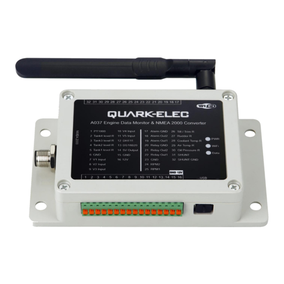
A037 Engine Data Monitor & NMEA 2000 Converter
Manual
.
Features
• Enable Analogue Signal Conversion to NMEA 2000 Messages
• Engine Data Monitoring and Tank Level Observation
• Pressure, Temperature, and Humidity Measurement
• RPM Tracking for Engine Speed
• Battery Status Check
• Alarm Status Observation
• Tilt/Trim and Rudder Position Observation
• Analogue Engine Gauge Data Conversion
• Compatibility with NMEA 2000 MFDs
V 1.0
1 of 44
2024
Advertisement
Table of Contents

Subscribe to Our Youtube Channel
Related Manuals for Quark-Elec A037


Summary of Contents for Quark-Elec A037
- Page 1 A037 Manual A037 Engine Data Monitor & NMEA 2000 Converter Manual Features • Enable Analogue Signal Conversion to NMEA 2000 Messages • Engine Data Monitoring and Tank Level Observation • Pressure, Temperature, and Humidity Measurement • RPM Tracking for Engine Speed •...
-
Page 2: Table Of Contents
A037 Manual Contents Introduction ............................4 Mounting/ Installation ........................4 2.1. Mounting Location ......................5 For Use Without Analogue Gauges ..............5 For Parallel Use with Existing Gauges: ..............5 2.2. Case Dimensions ....................... 5 Connections ............................. 6 3.1. Sensor Inputs ........................6 3.2. - Page 3 A037 Manual V 1.0 3 of 44 2024...
-
Page 4: Introduction
The A037 Engine Data Monitor & NMEA 2000 Converter is a state-of-the-art solution meticulously designed to enhance the monitoring capabilities of marine engines, ambient temperature and humidity. By utilizing the A037, users can ensure that their boat engines operate under optimal conditions, thereby extending their operational lifespan. -
Page 5: Mounting Location
A037 Manual 2.1. Mounting Location Select a flat location to mount the A037. Avoid mounting on uneven or contoured surfaces, as this could potentially fatigue the device casing. Ensure that the A037 is mounted in a suitable location appropriately between the NMEA 2000 bus and the senders or gauges. -
Page 6: Connections
A037 Manual 3. Connections The following is an example of an A037 set up. This gives an idea of the connections that need to be made to install A037. All these connections must be taken into consideration when locating a suitable mounting location for the A037. - Page 7 Same as DS18B20, The DHT11 operates on a 5V power supply, achieved by connecting its VCC to the 5V pinout on A037 (Pinout 14) and GND to either Pinout 6,15 or 23 on A037. Additionally, connect the Data wire to the DHT11 pinout on A037 (Pinout 12). Ensure to carefully review the connections before initiating the power-up process to prevent any possible permanent damage to the DHT11.
-
Page 8: Alarm And Relay Output
Four Tank level inputs. Resistive liquid tank level sensors are very commonly used to monitor the liquid level in boats water tanks. The A037 supports up to 4 tanks, which can be used to monitor fuel, fresh water, waste oil, live well and black water level. After connecting the sensors, the user will need to calibrate the sensor and setup the proper capacity value via the configuration tool. -
Page 9: Nmea 2000 Port
The A037 comes with an NMEA 2000 drop cable, facilitating its connection to the NMEA 2000 network. It's important to note that the A037 cannot be powered directly from the NMEA 2000 network. Instead, it must be powered through its 12V (Pinout 16) and GND (Pinout 15) pinouts using a 12V power supply. -
Page 10: Status Leds
The A037 features one PT1000 temperature sensor input. Figure 8 PT1000 RTD Sensor Probe Upon connecting the temperature sensor to the A037 for the first time, it's essential to use the windows- based configuration tool, which can be downloaded from our website, to configure the A037 to seamlessly work with the PT1000 sensor. - Page 11 A037 Manual 2. Connect the A037 to a Windows PC using the provided USB cable. For users running Windows 10 or an earlier version of the operating system, it may be necessary to install a device driver to recognize the A037 USB port. The latest driver can be found from Quark-elec website.
-
Page 12: N2K Output Settings
A037 Manual Figure 9 PT1000 calibration 4.2. N2K Output Settings Please click on the “N2K Output Settings” tab to set up the output PGN. 1. Select “PGN 130312: Temperature” from the dropdown menu. 2. Select “Instance 0” if you are setting up the first temperature sensor, “Instance 1” will be used for the second temperature sensor, etc. -
Page 13: Tank Level Sensor Inputs
Once the fluid level sensor has been connected to one of the tank level sensor pinouts on A037, the configuration tool (Windows PC application – can be downloaded from Quark-elec website) needs to be used to calibrate the sensor and to assign the correct input and the output N2K sentences. -
Page 14: Calibration
Pinout 5, and the other wire to GND (Pinout 6). 2. Connect the A037 to a Windows PC via USB. If you are using Windows 10 or a previous version of the Windows operating system on your computer, a device driver might have to be installed first for the computer to be able to recognize the A037. -
Page 15: European Or American Standard's Sensor
A037 Manual 3. For the empty tank, we would suggest you enter a small number, e.g., 0 or 1. This percentage will be displayed by your chart plotter when the tank is empty. 4. Fill up you tank to 20% of its capacity and repeat the steps above. -
Page 16: N2K Output Settings
5. From the Input dropdown list select the Pinout number to which the sensor is connected. In our example is “Tank 4: Pinout (2)” 6. Tick the checkbox next to “Enable PGN” to activate it. 7. Finally, click Save to save these new setting to your device and repower the A037. V 1.0 16 of 44... -
Page 17: Voltage Sensor Inputs
6.1. Input Pinout Settings The A037 supports up to 32VDC input voltage. A sensor typically is using two wires or pins to output, one is used for the output voltage, the other is for GND. Connect the output voltage wire to one of the voltage input pinouts (e.g., in below example its V2 input, Pinout 8) and the other wire to one of the GND... - Page 18 A037 Manual 3. Launch the configuration tool on the computer. Ensure that the “Connected” status message with the firmware version and configuration tool version appears at the bottom of the window before changing any settings. 4. Click on the “Input Pinout settings” tab and select “Volts 2: Pinout(8)” from the dropdown menu.
-
Page 19: Calibration
Please use this information to fill in the “Data Output Set” table in the configuration tool. In this example, for a measured value of 0.5, the A037 will output 0 Bar. For 1.5, the A037 will output 1.72 Bar, etc.. -
Page 20: Tacho Inputs (Rpm)
Connect the negative connection of the ignition coil to the RPM. And connect GND to GND of A037. If there is only one wire from ignition coil or alternator, then just don’t connect this. Single wire (negative connection) is sufficient. -
Page 21: Hall Effect And Electronic Pulse Senders
Figure 23 Alternator wiring 7.3. Hall Effect and Electronic Pulse Senders Connect the signal line of the sender to the RPM on the A037 and connect GND to GND pinout of A037. Figure 24 Hall Effect & Electronics Pulse sensor wiring 7.4. -
Page 22: N2K Output Settings
5. The last step is to tick the box next to “Enable PGN” and to click Save to save the new settings to the device. Repower the A037 Engine Data Monitor after the setup process to activate the new settings. -
Page 23: Shunt Input
Engine Data Monitor does not come with an electrical shunt, however, the Quark-elec A016 battery monitor with a shunt can be used with the A037 to measure the current. This can be purchased directly from Quark-elec’s website or from an authorized Quark-elec distributor, reseller or installer. -
Page 24: Calibration & N2K Output Settings
Figure 28 Shunt input settings 8.2. Calibration & N2K Output Settings The above is an example of how to set up a 100Amp A016 Battery Monitor shunt with the A037 Engine Data Monitor. The steps are the following: 1. Click on the “Input Pinout Settings” tab and select “SHUNT: Pinout(31)” from the dropdown menu. -
Page 25: Rudder R Input
3. Select “SHUNT: Pinout(31)” for Current. 4. If a voltage sensor or case temperature sensor is also connected to the A037, these sensor data can also be added to this PGN if required by selecting the Pinouts from the Voltage and Case Temperature dropdown lists to which these sensors are connected. -
Page 26: Input Pinout Settings
If not, the rudder angle will have to be measured during the setup. The A037 can be set up to convert sensor data to an NMEA 2000 PGN as shown below: V 1.0... - Page 27 A037 Manual Figure 31 Rudder sensor calibrations Please follow the steps below to set up the rudder angle sensor: 1. Click on Input Pinout Settings tab and select “Rudder: Pinout(27)” from the dropdown list. 2. Enter the maximum and minimum values of the angle the sensor can measure.
-
Page 28: Coolant Temp R Input
10. Coolant Temp R Input In addition to the other inputs listed in this manual, the A037 also features a coolant temperature sensor input and allows the user to connect an existing resistive coolant temperature sensor to the A037. This sensor is based on a temperature-variable resistor, it is connected to the engine’s cooling system and... - Page 29 Please follow the steps below to calibrate the sensor: 1. Connect the sensor to the A037, to Pinout 28 (Coolant Temp R) and to Pinout 23 (GND). 2. Launch the configuration tool on your computer and click on the “Input Pinout Settings” tab.
-
Page 30: Air Temp R Input
The first step is the calibration of the sensor. The calibration of the air temperature sensor must be done with the sensor connected to the A037. Remember, that to be able to calibrate the sensor accurately, a thermometer will also be required. When calibrating the temperature sensor, we would suggest starting with the lowest temperature or the highest temperature and going through the required temperature range by recording the sensor output and the actual temperature at regular intervals. - Page 31 A037 Manual Figure 35 Air Temp output settings Please follow the steps below to calibrate the temperature sensor: 1. Click on Input Pinout Settings tab and select “Air Temp: Pinout(29)” from the dropdown list. 2. Select the required temperature unit (° K, ° F or ° C) from the Unit dropdown list.
-
Page 32: Oil Pressure R Input
5. Click on the “N2K Output Settings” and select “PGN 130312: Temperature” from the dropdown list. 6. Select “Instance 0” for Instance if this is the first temperature sensor connected to the A037. If multiple temperature sensors are connected to the A037, the first sensor should have “Instance 0”, the second temperature sensor should have “Instance 1”, etc. - Page 33 Try to spread out the data pairs evenly between the lowest and highest values. 7. Click Save to save the data and the new settings to the device and repower the A037. V 1.0...
-
Page 34: Monitor The N2K Output Via Wifi
Monitoring software (e.g., SSCOM) can be used if required to check the data stream output by the A037, to ensure that the required PGN is part of the data stream. -
Page 35: Configuration (Via Usb)
• In Standby mode, the WiFi connection is disabled. The A037 is set to Ad-hoc mode as a default setting but can be easily set up to Station or Standby mode through the configuration tool. To check or to modify the WiFi settings, power up your A037 and connect it to your Windows computer via USB. -
Page 36: Wifi Station Mode
Click Save to save the new settings to the A037 and repower your device. Wait for 10-15 seconds for the A037 to boot up and on your laptop or mobile device scan for a WiFi network with an SSID of QK- A037_xxxx or the new SSID you have entered. -
Page 37: Wifi Standby Mode
Port: by default, the port number is 2000. Click Save to save the new settings to the A037 and repower your device. Wait for 10-15 seconds for the A037 to boot up and on your laptop or mobile device scan for your router’s WiFi network and connect to the network using the router’s password. -
Page 38: Input Pinout Settings
A037 Manual Figure 42 WiFi settings (Standby) To set the A037’s WiFi adapter to Standby mode, select “Standby” from the Mode dropdown menu. Click Save to disable the A037’s WiFi adapter and repower your device. 14.2. Input Pinout Settings To ensure optimal functionality and accurate data transmission on the NMEA 2000 data bus, it is necessary to configure the input sensors properly. -
Page 39: Output Pinout Settings
12V interface devices, while relay only works with 5V. The A037 can be configured to trigger an external alert or alarm devices which can be accessed from the configuration tool, by choosing Output Pinout Settings. -
Page 40: N2K Output Pinout
6. The last step is to select one of the available options for Action. These are the following: Figure 47 Output pinout settings (Action type) 7. Click Save to save the new settings to your device and repower the A037. 14.4. N2K Output Pinout The A037 outputs the following PGNs when a related sensor connected and proper configured. -
Page 41: Upgrading Firmware
1FD0A Pressure To enable the A037 to output data via the NMEA 2000 network, you must ensure that the “N2K Output Settings” have been configured correctly. All supported N2K PGNs are listed in the drop-down tab, with detailed setup instructions available in the related input sensor sections (Section 4 to Section 11). -
Page 42: Factory Reset
Due to different reasons, it might be required to restore the A037 to its factory settings. This might be required if the A037 is transferred to another boat equipped with different type of sensors or if the boat is being refitted with a new set of sensors and devices. In these cases, the CTRL+F5 key combination can be used to delete all settings, instead of having to reset all settings manually. -
Page 43: Limited Warranty And Notices
Quark-elec warrants this product to be free from defects in materials and manufacture for two years from the date of purchase. Quark-elec will, at its sole discretion, repair or replace any components that fail in normal use. Such repairs or replacement will be made at no charge to the customer for parts and labour. -
Page 44: Document History
SHUNT: a shunt is an electrical device that allows the measurement of electrical current in a circuit. 22. For more info… For more technical information and other enquiries, please go to the Quark-elec forum at: https://www.quark-elec.com/forum/ For sales and purchasing information, please email us: info@quark-elec.com...
Need help?
Do you have a question about the A037 and is the answer not in the manual?
Questions and answers