Table of Contents
Advertisement
Quick Links
Advertisement
Table of Contents

Related Manuals for OSO HOTWATER Maxi Marine MM


Summary of Contents for OSO HOTWATER Maxi Marine MM
- Page 1 Maxi Marine - MM/MME/MMC/MMCE 120-15 000 l. SAFETY INFORMATION O&M INFORMATION INSTALLATION MANUAL Manufactured by OSO Hotwater AS Industriveien 1 - 3300 Hokksund - Norway Tel: + 47 32 25 00 00 / E-mail: oso@oso.no www.osohotwater.com 11002273-06 - 04-2024...
-
Page 2: Table Of Contents
CONTENTS 1. Safety instructions ............. 3 General information ......... 3 1.2 Safety instructions for users ......4 1.3 Safety instructions for installers ....4 2. Product description ..........5 2.1. Product identification ........5 2.2. Intended use ............5 2.3 CE marking ............5 2.4 Technical data ............ -
Page 3: Safety Instructions
1. SAFETY INSTRUCTIONS 1.1 General information • Read the following safety instructions carefully before installing, maintaining or adjusting the buffer tank. • Personal injury or material damage may result if the product is not installed or used in the intended manner. •... -
Page 4: Safety Instructions For Users
1.2 Safety instructions for users WARNING The overflow from any safety valve shall NOT be sealed or plugged. The product must NOT be modified or changed from its original state. Children must NOT play with the product or go near it without supervision. Maintenance/settings shall only be carried out by persons over 18 years of age, with sufficient understanding CAUTION... -
Page 5: Product Description
• Pressurized equipment PED 2014/68/EU • Safety standard EN 60335-2-21 The CE mark shows that the product complies with the relevant Directives. See Declaration of OSO Hotwater is certified for Conformity at www.osohotwater.com for more • Quality ISO 9001 information. • Environment ISO 14001 •... -
Page 6: Instructions For Installation, Operation
3. INSTRUCTIONS FOR INSTALLATION, OPERATION AND MAINTENANCE 3.1 Products covered by these instructions Maxi Marine Buffer tank - MM 120-5000 Maxi Marine Coil - MMC 120-5000 Maxi Marine Electric - MME 120-5000 Maxi Marine Coil + Electric - MMCE 120-5000 3.2 Specs and installation The OSO Maxi Marine series is manufactured to customer specifications. -
Page 7: Delivery, Location And Installation
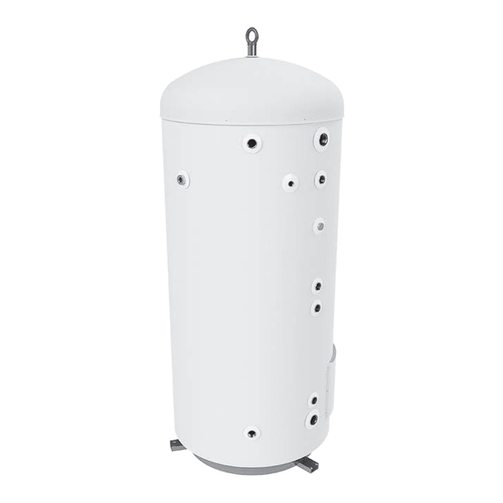
4. DELIVERY, LOCATION AND INSTALLATION 4.1 Delivery The product should be transported carefully to its designated location, with packaging. CAUTION Pipe stubs, valves etc. should not be used to lift the product as this could cause malfunctions. Products larger than 400 l. are fitted with a lift- ing lug (L), see illustration. -
Page 8: Pipe Installation
4.3 Pipe installation 4.3.1 Nozzles Dimension Connection description 1” internal thread Lifting lug 1 1/2” internal thread Potable hot water outlet 1” internal thread P&T safety valve 1/2” internal thread Thermometer 1 1/2” internal thread Hot water circulation - HWC 1”... - Page 9 4.5.3 Maintenance (also see pt. 5.2) Cleaning the pressure vessel: Open the cold potable water flow fully for approx. 1 hour. It is recommended to check all pipe connections for leaks after approx. 3 months service and then annually to avoid unwanted water spillage, with possible damage to the vessel or its surroundings.
-
Page 10: Electrical Installation
4.6 Electrical installation Fixed electrical fittings must be used for installa- tion. Any electrical fittings must be installed by an authorised electrician. The relevant standards and regulations must be followed. 4.6.1 Electrical components - if fitted (options available on customer request) Component Note Safety thermostat 98°C thermal cut-out... -
Page 11: Wiring Diagrams, Schematic
4.7 Wiring diagrams, schematic WARNING OSO Maxi Marine products can be fitted with cus- Constant voltage is present at the terminals. tomer specified electrical layout. The shown sche- Before any electrical work is done, the power matics are standard layouts, see electrical specifica- supply must be disconnected and secured tions for your product for the correct layout. - Page 12 4.7.2 Wiring diagram WARNING Junction box with 6 elements. Max. voltage Constant voltage is present at the terminals. 480V. Supply cable is connected to terminal (5) Before any electrical work is done, the power as shown. Supply wires shall be secured with supply must be disconnected and secured suitable strain relievers.
- Page 13 4.7.4 Fitting instructions WARNING The product must be filled with water before the power is switched on. Fixed electrical fittings must be used for installation according to the regulations. Any electric fittings must be installed by an authorised electrician. The mains cable shall withstand 90°C. A suitable strain reliever must be fitted. CAUTION The product must have a clearance for servicing of 40 cm in front of the junction box cover.
-
Page 14: K12 Terminal Box - Optional
4.8 K12 terminal box - optional The K12 terminal boxes (1) is approved for installation in boilers designed for heating of water. It is possible to fit multiple K12 el- ements in one boiler, each with a separate power supply. Effect 230 / 690V - Max. - Page 15 4.8.1 Wiring diagrams - K12 terminal box Effect 230 / 690V - Max. 3x20A - voltage de- pending on element type. WARNING Constant voltage is present at the terminals. Before any electrical work is done, the power supply must be disconnected and secured against activation while the work is in pro- gress.
-
Page 16: Initial Commissioning
5. INITIAL COMMISSIONING 5.1 Filling with water First check that all pipes are connected correctly. Then fill the tank according to the needs/require- ments of the system. Make sure that the tank is vented during filling to prevent air pockets. 5.2 Turning on the power When the cylinder has been filled with water, the power can be switched on (if fitted):... -
Page 17: User Guide
6. USER GUIDE 6.1 Settings turned back on. 6.1.1 Thermostat setting (not K12 terminal box) • Inspection of safety valve operation, see pt. 5.3. The thermostats are adjustable from 40-70°C or 60-90°C depending on spec. The thermostat should not be set lower than 65°C to prevent bac- WARNING teria growth. -
Page 18: Contact Details - Installer
Contact details - installer CONTACT INFORMATION Installed by (company): Company address: Company telephone: Company email: Installer name: Installation date: Notes This document should be kept in a suitable place where it is accessible for future reference. -
Page 19: Warranty Conditions
7. WARRANTY CONDITIONS 1. Scope should not be aggressive, i.e. the water chemistry shall OSO Hotwater AS (hereinafter called OSO) warrants for 2 years comply with the following: from the date of purchase, that the Product will: i) conform to... - Page 20 OSO Hotwater AS Industriveien 1 3300 Hokksund - Norway Tel: + 47 32 25 00 00 oso@oso.no www.osohotwater.com © This installation manual and all its content is protected by copyright and may be reproduced or distributed only with written consent from the manufacturer.
Need help?
Do you have a question about the Maxi Marine MM and is the answer not in the manual?
Questions and answers