Advertisement
Quick Links
Abmessungen
LED ye
LED gn
LED gn
Alle Abmessungen in mm
Elektrischer Anschluss/Kurven/Zusätzliche Informationen
Charakteristische Ansprechkurve
Abstand Y [mm]
1800
ebene Platte 100 mm x 100 mm
1500
1200
900
1
+U B
600
5
300
Synchronisation
0
2
-300
Lerneingang
-600
4
Analogausgang
-900
3
-1200
-U B
-1500
Rundstab Ø 25 mm
-1800
0
1
5
2
4
3
Adernfarben gemäß EN 60947-5-2
1
BN
(braun)
2
WH
(weiß)
3
BU
(blau)
4
BK
(schwarz)
5
GY
(grau)
Technische Daten
Allgemeine Daten
Erfassungsbereich
200 ... 4000 mm
Einstellbereich
240 ... 4000 mm
Blindzone
0 ... 200 mm
Normmessplatte
100 mm x 100 mm
Wandlerfrequenz
ca. 85 kHz
180 ms
Ansprechverzug
Anzeigen/Bedienelemente
LED grün
Betriebsanzeige
LED gelb
Objekt im Auswertebereich
LED rot
Störung
Elektrische Daten
Betriebsspannung
U
10 ... 30 V DC , Welligkeit 10 %
B
50 mA
Leerlaufstrom
I
0
Schnittstelle
Serielle Schnittstelle (Programmieradapter erforderlich)
Schnittstellentyp
9600 BPS, no parity, 8 data bits, 1 stop bit
Eingang/Ausgang
Ein-/Ausgangsart
1 Synchronisationsanschluss, bidirektional
0-Pegel
0 ... 1 V
1-Pegel
4 V ... U
B
Eingangsimpedanz
> 12 k
Ausgangsstrom
< 12 mA
Impulsdauer
0,5 ... 300 ms (1-Pegel)
62,5 ms (0-Pegel)
Impulspause
Synchronisationsfrequenz
16 Hz
Gleichtaktbetrieb
17 Hz / n , n = Anzahl der Sensoren , n 10
Multiplexbetrieb
(Werkseinstellung: n = 5 )
Eingang
Eingangstyp
1 Lerneingang
Pegel (Auswertegrenze 1)
0 ... 1 V
Pegel (Auswertegrenze 2)
4 V ... U
B
Eingangsimpedanz
> 12 k
Impulsdauer
2 ... 10 s
Ausgang
Ausgangstyp
1 Analogausgang 4 ... 20 mA
Auswertebereich [mm]/3200, jedoch 0,4 mm
Auflösung
0,2 % vom Endwert
Kennlinienabweichung
0,1 % vom Endwert
Reproduzierbarkeit
500 bei U
Lastimpedanz
300 bei U
1,5 % vom Endwert
Temperatureinfluss
Umgebungsbedingungen
Umgebungstemperatur
-25 ... 70 °C (-13 ... 158 °F)
Lagertemperatur
-40 ... 85 °C (-40 ... 185 °F)
Mechanische Daten
Anschlussart
Gerätestecker M12 x 1 , 5-polig
Schutzart
IP67
Material
Gehäuse
PA-GF35
Wandler
Epoxidharz/Glashohlkugelgemisch; Schaum Polyurethan
Masse
120 g
Werkseinstellungen
Auswertegrenze A1: 240 mm
Ausgang
Auswertegrenze A2: 4000 mm
Ausgangsfunktion: steigende Rampe
Schallkeule
breit
Allgemeine Informationen
Schalterstellung des externen Programmieradapters:
Ergänzende Informationen
"output load": pull-down
"output logic": noninv
Normen- und Richtlinienkonformität
Normenkonformität
EN 60947-5-2:2007
Normen
IEC 60947-5-2:2007
EN 60947-5-7:2003
IEC 60947-5-7:2003
Zulassungen und Zertifikate
UL-Zulassung
cULus Listed, General Purpose
CSA-Zulassung
cCSAus Listed, General Purpose
Produkte, deren max. Betriebsspannung 36 V ist, sind nicht zulassungspflichtig und daher nicht mit einer CCC-
CCC-Zulassung
Kennzeichnung versehen.
Dimensions
LED ye
67
40
5.5
46
ø 5.5
60
All dimensions im mm
1000
2000
3000
4000
5000
6000
7000
8000
Abstand X [mm]
Y
breite Schallkeule
X
schmale Schallkeule
SS
14V
B
< 14V
B
LED ye
LED gn
LED ye
LED gn
67
40
5.5
46
ø 5.5
60
Electrical Connection / Curves / Additional Information
1
+U B
5
Synchronization
2
Program input
4
Analog output
3
-U B
1
5
2
4
3
Wire colors in accordance with EN 60947-5-2
1
BN
(brown)
2
WH
(white)
3
BU
(blue)
4
BK
(black)
5
GY
(gray)
Technical data
General specifications
Sensing range
Adjustment range
Unusable area
Standard target plate
Transducer frequency
Response delay
Indicators/operating means
LED green
LED yellow
LED red
Electrical specifications
Operating voltage
U
B
No-load supply current
I
0
Interface
Interface type
Input/Output
Input/output type
0 Level
1 Level
Input impedance
Output rated operating current
Pulse length
Pulse interval
Synchronization frequency
Common mode operation
Multiplex operation
Input
Input type
Level (evaluation limit 1)
Level (evaluation limit 2)
Input impedance
Pulse length
Output
Output type
Resolution
Deviation of the characteristic curve
Repeat accuracy
Load impedance
Temperature influence
Ambient conditions
Ambient temperature
Storage temperature
Mechanical specifications
Connection type
Protection degree
Material
Housing
Transducer
Mass
Factory settings
Output
Beam width
General information
Supplementary information
Compliance with standards and directives
Standard conformity
Standards
Approvals and certificates
UL approval
CSA approval
CCC approval
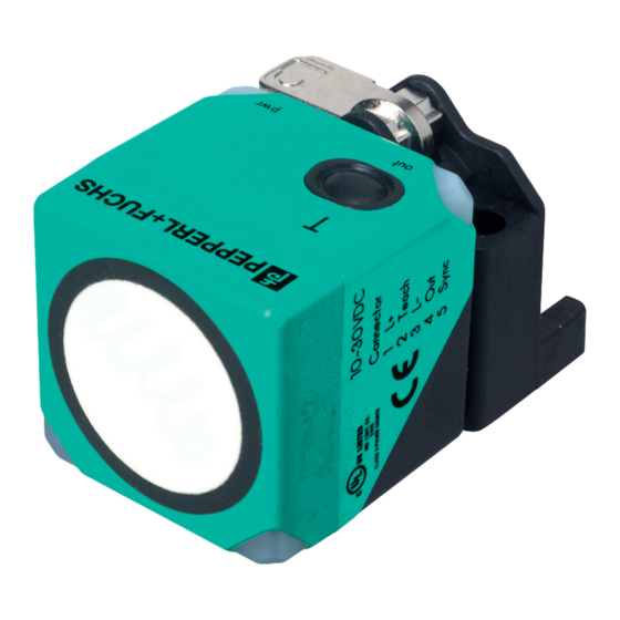
Ultraschallsensor
Ultrasonic sensor
UC4000-L2-I-V15
Characteristic response curve
Distance Y [mm]
1800
flat surface 100 mm x 100 mm
1500
1200
900
600
300
0
-300
-600
-900
-1200
-1500
round bar, Ø 25 mm
-1800
0
1000
2000
3000
4000
5000
6000
7000
8000
Distance X [mm]
Y
wide sound lobe
X
narrow sound lobe
200 ... 4000 mm
240 ... 4000 mm
0 ... 200 mm
100 mm x 100 mm
approx. 85 kHz
180 ms
Operating display
object in evaluation range
error
10 ... 30 V DC , ripple 10 %
SS
50 mA
Serial interface (programming adapter required)
9600 BPS, no parity, 8 data bits, 1 stop bit
1 synchronization connection, bidirectional
0 ... 1 V
4 V ... U
B
> 12 k
< 12 mA
0.5 ... 300 ms (level 1)
62.5 ms (level 0)
16 Hz
17 Hz / n , n = number of sensors , n 10
(factory setting: n = 5 )
1 program input
0 ... 1 V
4 V ... U
B
> 12 k
2 ... 10 s
1 analog output 4 ... 20 mA
Evaluation range [mm]/3200, however 0.4 mm
0.2 % of full-scale value
0.1 % of full-scale value
500 at U
14V
B
300 at U
< 14V
B
1.5 % of full-scale value
-25 ... 70 °C (-13 ... 158 °F)
-40 ... 85 °C (-40 ... 185 °F)
Connector M12 x 1 , 5-pin
IP67
PA-GF35
epoxy resin/hollow glass sphere mixture; polyurethane foam
120 g
evaluation limit A1: 240 mm
evaluation limit A2: 4000 mm
output function: rising slope
wide
Switch settings of the external programming adapter:
"output load": pull-down
"output logic": noninv
EN 60947-5-2:2007
IEC 60947-5-2:2007
EN 60947-5-7:2003
IEC 60947-5-7:2003
cULus Listed, General Purpose
cCSAus Listed, General Purpose
CCC approval / marking not required for products rated 36 V
Advertisement

Related Manuals for Pepperl+Fuchs UC4000-L2-I-V15


Summary of Contents for Pepperl+Fuchs UC4000-L2-I-V15
- Page 1 Ultraschallsensor Abmessungen Dimensions Ultrasonic sensor UC4000-L2-I-V15 LED ye LED gn LED ye LED ye LED gn LED ye LED gn LED gn ø 5.5 ø 5.5 Alle Abmessungen in mm All dimensions im mm Elektrischer Anschluss/Kurven/Zusätzliche Informationen Electrical Connection / Curves / Additional Information...
- Page 2 Adressen / Addresses / Adresses / Direcciónes / Indirizzi Contact Pepperl+Fuchs GmbH · 68301 Mannheim · Germany · Tel. +49 621 776-4411 · Fax +49 621 776-27-4411 · E-mail: fa-info@de.pepperl-fuchs.com Worldwide Headquarters: Pepperl+Fuchs GmbH · Mannheim · Germany · E-mail: info@de.pepperl-fuchs.com USA Headquarters: Pepperl+Fuchs Inc.
Need help?
Do you have a question about the UC4000-L2-I-V15 and is the answer not in the manual?
Questions and answers