Table of Contents
Advertisement
Quick Links
Advertisement
Table of Contents

Related Manuals for Pepperl+Fuchs LC10 Series


Summary of Contents for Pepperl+Fuchs LC10 Series
- Page 1 FACTORY AUTOMATION MANUAL LC10-* Laying loops for Loop detector LC10-1 and LC10-2...
- Page 2 Manual LC10-* With regard to the supply of products, the current issue of the following document is ap- plicable: The General Terms of Delivery for Products and Services of the Electrical Indus- try, published by the Central Association of the Electrical Industry (Zentralverband Elektrotechnik und Elektroindustrie (ZVEI) e.V.) in its most recent version as well as the supplementary clause: "Expanded reservation of proprietorship"...
-
Page 3: Table Of Contents
Manual LC10-* Introduction..................Contents....................Target Group, Personnel................ Symbols Used ..................General safety instructions ............Product Description ..............Overview ....................Use and Application ................Indicators and Operating Controls............3.3.1 LC10-1-* ....................3.3.2 LC10-2-* ....................Interfaces and connections ..............Dimensions..................... Installation..................Preparation ..................... 4.1.1 Laying loops.................. - Page 4 Manual LC10-*...
-
Page 5: Introduction
Manual LC10-* Introduction Introduction Contents This document contains information that you need in order to use your product throughout the applicable stages of the product life cycle. These can include the following: Product identification Delivery, transport, and storage Mounting and installation Commissioning and operation Maintenance and repair Troubleshooting... -
Page 6: Symbols Used
Manual LC10-* Introduction Symbols Used This document contains symbols for the identification of warning messages and of informative messages. Warning Messages You will find warning messages, whenever dangers may arise from your actions. It is mandatory that you observe these warning messages for your personal safety and in order to avoid property damage. -
Page 7: General Safety Instructions
Manual LC10-* General safety instructions General safety instructions Note! Read the operating instructions before attempting commissioning. Caution! Installation, connection and adjustments should only be undertaken by specialist personnel. Warning! No safety component for protection of personnel or EMERGENCY-STOP functions. Directives and Standards EU-Directive Standards 2014/30/EU... -
Page 8: Product Description
Manual LC10-* Product Description Product Description Overview Together with the inductive loops laid beneath the surface, the LC series loop detectors form a universal sensor system for detecting vehicles. People are not detected. Vehicles that enter the inductive loop change the resonant frequency. This frequency change is measured and analyzed by the microprocessor in the LC10 loop detector. -
Page 9: Indicators And Operating Controls
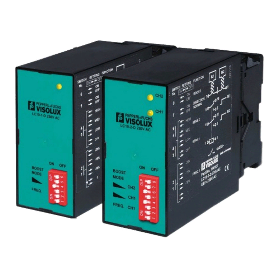
Manual LC10-* Product Description Indicators and Operating Controls 3.3.1 LC10-1-* LED indicator DIP switch LED indicator LED signals the allocation state of the loop (Loop allocated = LED On). A fault in the loop due to a short-circuit or lead breakage and loop inductance outside the permissible range is indicated by flashing of LED. - Page 10 Manual LC10-* Product Description 3.3.2 LC10-2-* LED indicator loop 2 LED indicator loop 1 DIP switch LED indicators Indications: LEDs 1 and 2 signal the allocation state of the loops (Loop 1 allocated = LED 1 on, Loop 2 allocated = LED 2 on). A fault in a loop due to a short-circuit or lead breakage and loop industance outside the permissible range is indicated by flashing of the respective LED.
-
Page 11: Interfaces And Connections
Manual LC10-* Product Description operating mode switches The following operating modes can be set with switches 7 and 8: switch 7 switch 8 result Output of the loop allocation status Direction detection* Increased sensitivity (Boost) Table 3.6 *A signal is output, depending on the allocation sequence of the loops. If loop 1 is allocated before loop 2, only one switch signal is output for loop 1. -
Page 12: Dimensions
Manual LC10-* Product Description Connections LC10-2 SL 1 SL 2 SL 1 SL 2 Number Explanation Connector terminals Loop connection, Loops 1/2 7/8 = loop 1 8/9 = loop 2 Signal output, Loop 1 5/6 = NO 6/10 = NC Signal output, Loop 2 3/4 = NO 4/11 = NC... -
Page 13: Installation
Manual LC10-* Installation Installation Preparation 4.1.1 Laying loops Laying loops in asphalt or concrete floors When laying loops in asphalt or concrete floors the loop can be produced in commercial grade insulated copper braid HO7V-K1.5(NYAF) with a cross section of 1.5 mm². A groove approx. -
Page 14: Loop Test
Manual LC10-* Installation Adjacent loops of the same circumference should differ from each other by 1 winding. This prevents the loops from operating on the same frequency. 4.1.3 Loop test After laying and sealing the insulating resistance of the loop must be measured against earth. It must be at least 1 MOhm. -
Page 15: Commissioning
Manual LC10-* Commissioning Commissioning When the operating voltage is applied to the device automatic adjustment with the loop takes place. The output relays are switched in the switch position "loop not allocated". The adjustment takes 2 s, then the device is ready for operation. Automatic adjustment also takes place when both sensitivity switches 3 and 4 (Loop 1) and 5 and 6 (Loop 2) are set to "OFF"... -
Page 16: Loop Interference
Manual LC10-* Commissioning Detection of trucks roadway ~ 1 m driving direction Detection of two-wheeled vehicles (motorcycle, bicycle) roadway 0,9 m 0,2 m 45˚ driving direction Loops with reduced side sensitivity Sliding doors Selection gates Folding doors Loop interference Interference from adjacent loops Loops connected to different loop detectors must have a minimum distance of 2 meters from each other and operate on different frequencies. -
Page 17: Influencing Variables
Manual LC10-* Commissioning > 2 m SD IND 2.1 SD IND 1.1 > 2 m SD IND 1.1 SD IND 1.1 Interference from metal Fixed metal constructions e.g. steel girders, drains, steel reinforcements are integrated in the automatic compensation of the loop detector and do not affect the safe functioning except for a reduced sensitivity. -
Page 18: Troubleshooting
Manual LC10-* Troubleshooting Troubleshooting Before requesting a service call, please check that the following actions have been taken: Equipment has been tested according to the following checklists. Telephone assistance has been obtained from the Service Center in order to isolate the problem. - Page 19 Twinsburg, Ohio 44087 · USA Tel. +1 330 4253555 E-mail: sales@us.pepperl-fuchs.com Asia Pacific Headquarters Pepperl+Fuchs Pte Ltd. Company Registration No. 199003130E Singapore 139942 Tel. +65 67799091 E-mail: sales@sg.pepperl-fuchs.com www.pepperl-fuchs.com Subject to modifications / DOCT0973C Copyright PEPPERL+FUCHS • Printed in Germany 11/2016...
Need help?
Do you have a question about the LC10 Series and is the answer not in the manual?
Questions and answers