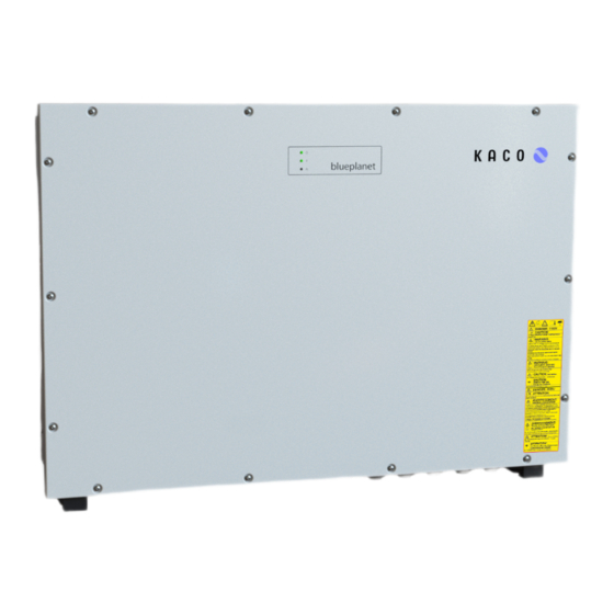
Kaco blueplanet 100 NX3 Manual

Kaco blueplanet 100 NX3 Manual

Hide thumbs Also See for blueplanet 100 NX3:
Table of Contents

Advertisement

Quick Links

Manual
nEnglish translation of German original
Authorised electrician
Important safety instructions
These instructions form part of the product and must be carefully read, observed and stored in a place which is freely accessible at all
times.
KACO blueplanet 100 NX3
KACO blueplanet 125 NX3
B/ M/ MF

Advertisement

Table of Contents
loading
Need help?

Need help?

Do you have a question about the blueplanet 100 NX3 and is the answer not in the manual?

Questions and answers

Summary of Contents for Kaco blueplanet 100 NX3

  • Page 1 KACO blueplanet 100 NX3 KACO blueplanet 125 NX3 B/ M/ MF Manual nEnglish translation of German original Authorised electrician Important safety instructions These instructions form part of the product and must be carefully read, observed and stored in a place which is freely accessible at all...
  • Page 2 | Legal provisions Manual Legal provisions The information contained in this document is the property of KACO new energy GmbH. Publication of this document, in whole or in part, is subject to the written consent of KACO new energy GmbH. KACO warranty For current warranty conditions contact your system integrator.
  • Page 3: Table Of Contents

    15 Appendix............. 116 7.9 Sealing the connection area ......34 15.1 EU Declaration of Conformity ....... 116 15.2 Standards & directives ........116 8 Commissioning............ 35 8.1 Requirements ..........35 KACO blueplanet 100 NX3 KACO blueplanet 125 NX3 Page iii...
  • Page 4: General Information

    Storing the documents These instructions and other documents must be stored near the system and be available at all times. – The current version of the manual can be downloaded from www.kaco-newenergy.com. English translation of German original This document has been produced in several languages. The German-language version is the original version. All other language versions are translations of the original version.
  • Page 5: Identification

    Grid Support Interactive Inverter ARC fault circuit protection none Interface protection according to country specific requirements, details see manual – Technical data – Disposal information Fig. 1: Name plate – Certification marking, CE marking. KACO blueplanet 100 NX3 KACO blueplanet 125 NX3 Page 5...
  • Page 6: Warnings On The Device

    Toucher. ATTENTION: – Knowledge and adherence to this document with all safety notices. Une Entrée d’Eau peut Endommager l’Électronique de l’Appareil ► En cas de pluie, ne pas ouvrir l’appareil. Page 6 KACO blueplanet 100 NX3 KACO blueplanet 125 NX3...
  • Page 7: Safety

    The device is intended for indoor and outdoor applications and may only be used in countries for which it has been ap- proved or for which it has been released by KACO new energy and the grid operator. Operate the device only with a permanent connection to the public power grid. The country and grid type selection must be commensurate with the respective location and grid type.
  • Page 8: Protection Features

    IEC 60364-6 6.4.3.3 describes two options for this case. The first option is to disconnect devices with an over- voltage conductor or, if this is not practicable, then the test voltage can be reduced to 250V. Page 8 KACO blueplanet 100 NX3 KACO blueplanet 125 NX3...
  • Page 9: Description Of The Device

    3.2.3 Interfaces You can configure the interfaces and the web server in the Settings menu. The device has the following interfaces for communication and remote monitoring: KACO blueplanet 100 NX3 KACO blueplanet 125 NX3 Page 9...
  • Page 10 In addition to the safety functions, the internal interface switches can also be actuated via the "Inverter Off" input. If a Powador-protect is used as the central interface protection, the fail-safe disconnection of suitable KACO inverters from the public grid can be carried out by the internal interface switches instead of separate interface switches. This re- quires the inverters in the photovoltaic system to be connected to the Powador-protect.
  • Page 11: System Layout

    Grid connection point The clean PV-current is made available at the grid connec- tion point. DC isolator switch Use the DC isolator switch to disconnect the device from the PV generator. KACO blueplanet 100 NX3 KACO blueplanet 125 NX3 Page...
  • Page 12: Technical Data

    IEC 61730 Class A. Under no circumstances may the design lead to a short-circuit current greater than the ISC of the device [See section 7.6.4} Page 28]. Page KACO blueplanet 100 NX3 KACO blueplanet 125 NX3...
  • Page 13: General Data

    1, Class A* *DC→ > 20 kVA ≤ 75 kVA EN IEC 61000-6-4:2019 EN 61000-6-4:2007 back +A1:2011 Secondary effects on the grid: EN 61000-3-11:2000 EN IEC 61000-3-11:2019 EN 61000-3-12:2011 KACO blueplanet 100 NX3 KACO blueplanet 125 NX3 Page...
  • Page 14: Environmental Data

    Daisy chain AC input plate kit bp100NX3/125NX3 (double row) 1002173 Multicore AC input plate kit bp100/125NX3 (M63 / M32) 1002160 AC SPD type 1+2 kit bp100NX3/125NX3 (3+1) 3016362 USB wifi adapter bp100NX3/125NX3 Page KACO blueplanet 100 NX3 KACO blueplanet 125 NX3...
  • Page 15: Transportation And Delivery

    Sym- Contour screw Sym- Contour screw head head Tightening torque Outer hexagon Internal hexagon Spanner size or number Torx Slot Outer contour Tab. 2: Legend Description Tool abbreviation Fig. 10: Presentation format KACO blueplanet 100 NX3 KACO blueplanet 125 NX3 Page...
  • Page 16: Assembly And Preparation

    – Close to the ground, accessible from the front and sides without requiring additional resources. – In outdoor areas, KACO new energy recommends protecting the device from direct weather exposure and sunlight. This should be carried out by means of constructional measures (e.g. wind breaks) in order to reduce thermal heating of the components, premature derating and more extensive wear of the fans.
  • Page 17: Unpacking The Device

    1. Only lift the device using the openings provided. 2. The device must be transported and installed by at least 3-4 persons. 3. Be mindful of the weight of the device and use aids to secure it. KACO blueplanet 100 NX3 KACO blueplanet 125 NX3 Page...
  • Page 18: Preparing The Installation Location

    1. Use only fixing materials that are suitable for the mounting base. The fastening materials supplied are only to be used for masonry and concrete. 2. Only install the device in an upright hanging position. Page KACO blueplanet 100 NX3 KACO blueplanet 125 NX3...
  • Page 19 . NOTE: The minimum clearances between two devices, or the device and the ceiling or floor have already been taken into account in the diagram. 4. Drill the holes at the marked position and insert the dowels all the way into the wall surface. KACO blueplanet 100 NX3 KACO blueplanet 125 NX3 Page...
  • Page 20: Installing And Securing The Device

    2. Hook the device into the 4 fastening screws for the wall / mounting frame by way of the rear keyholes. Make sure that all screws are seated properly so that the back of the device is flush with the wall / mounting frame ( [See figure 18 [} Page 19]). Page KACO blueplanet 100 NX3 KACO blueplanet 125 NX3...
  • Page 21 1. Seal off any plug-in connections and screw fittings using sealing covers. 2. Prior to installation, check the inner area for condensation and if necessary, allow it to dry sufficiently before installa- tion. 3. Immediately remove any moisture from the housing. KACO blueplanet 100 NX3 KACO blueplanet 125 NX3 Page...
  • Page 22: Installation

    Fig. 24: Connection area M8 version Fig. 25: Connection area M10 version AC connection point AC overvoltage protection (plugged in) DC connection point AC earthing bolt DC overvoltage protection (plugged in) Page KACO blueplanet 100 NX3 KACO blueplanet 125 NX3...
  • Page 23: Making The Electrical Connection

    RJ45 PID connection type defined by external solution (e.g. Padcon) Option: 50 mm² with 2x5 AC cable (for daisy chain). The optionally available input plate is required for this! [See section 4.4} Page 14] KACO blueplanet 100 NX3 KACO blueplanet 125 NX3 Page...
  • Page 24: Connecting The Device To The Power Grid

    Otherwise, the aluminium may be destroyed by the copper busbars in the presence of electrolytes (e.g. con- densate). If the connection is made in a TN-C grid, connect the PEN grounding cable to the ground earthing point. Page KACO blueplanet 100 NX3 KACO blueplanet 125 NX3...
  • Page 25: Connecting The Pv Generator To The Device

    [See section 9.4.2} Page 48]. This can affect the efficiency somewhat. If one of these types is used, it must have a protective rating of at least 1250 mA. For questions regarding the appropriate type, please contact the installer or our KACO new energy customer service.
  • Page 26 (MPP trackers 1 and 2). Per MPP tracker P (M8) respectively (M10) the recommended PV generator power. current per tracker < max. rated current (DC) max: Tab. 3: Electrical data of the installation Page KACO blueplanet 100 NX3 KACO blueplanet 125 NX3...
  • Page 27 : ≤ 2 * max. rated current (DC) Tab. 4: Electrical data of the installation 7.6.3 Configuring the DC plug connector Fig. 31: Insert wires Fig. 32: Slide insert into sleeve Fig. 33: Check fastening KACO blueplanet 100 NX3 KACO blueplanet 125 NX3 Page...
  • Page 28 PV generator. The absolute limit for the PV generator is the value of the max. short-circuit current (ISC .) and the max. no-load voltage (U ). See footnote under [See section 4.1} Page 12] DCmax. Page KACO blueplanet 100 NX3 KACO blueplanet 125 NX3...
  • Page 29: Establishing Equipotential Bonding

    Depending on the local installation specifications, it may be necessary to earth the device with a second ground connection. To this end, the threaded bolt on the underside of the device can be used. KACO blueplanet 100 NX3 KACO blueplanet 125 NX3 Page...
  • Page 30: Connecting The Interfaces

    3 DIP switch - activate terminator 7 USB socket 4 INV OFF - connection for external grid protection 8 ERR – fault signal relay component - 24 V(+/- 20%) / 1 A (at least 15 mA) Page KACO blueplanet 100 NX3 KACO blueplanet 125 NX3...
  • Page 31 You can use both crossed and 1:1 protectively-wired Ethernet connection cables. ↻ Connecting cable inside the device. 1. Plug in an Ethernet cable at one of the two Ethernet ports on the communication circuit board. KACO blueplanet 100 NX3 KACO blueplanet 125 NX3 Page...
  • Page 32 - Wire A (-) to wire A (-) and wire B (+) to wire B (+) Fig. 40: Assignment of twisted-pair - GND to GND wires 5. Tighten cable fittings [ W_20 / 1,5 Nm ]. Page KACO blueplanet 100 NX3 KACO blueplanet 125 NX3...
  • Page 33 1. Please note the corresponding application note under Downloads and Videos in the category PV ac- cessories - powador-protect. 2. When using devices from other manufacturers or in combination with KACO inverters, interface switches as a minimum must be used for shutting down devices from other manufacturers.
  • Page 34: Sealing The Connection Area

    2. Secure the housing cover (1) by tightening all 14 screws (2) in a diagonally op- posite sequence [ T_25/ 4 Nm ð The device has been mounted and installed. ð Put the device into operation. Fig. 43: Closing the housing cover Page KACO blueplanet 100 NX3 KACO blueplanet 125 NX3...
  • Page 35: Commissioning

    F Attach the provided safety sticker to the outside of the device housing where it is sources de tension - Réseau de distribution -Panneux photovoltaïques clearly visible. Fig. 44: Adhesive label UTE_C15-712-1 KACO blueplanet 100 NX3 KACO blueplanet 125 NX3 Page...
  • Page 36: Network Topologies

    >100m) it may also be necessary to connect in segments that are further away via a glass fibre connection. Within a segment, it is possible to link KACO devices to one another as part of an Ethernet daisy-chain by way of an integ- rated switch, whereby the Segment Controller is connected at the first element in the chain.
  • Page 37: Start-Up Options

    If such an adapter is not available, the other option is to perform an automatic configuration using a USB memory stick. The following figure provides an example of the structure of a KACO device with string combiner (SC) and mobile devices connected without cables.
  • Page 38 Manual 8.4.2 Start-up via LAN connection The following figure provides an example of the structure of a KACO device with string combiner (SC) and mobile devices connected directly via Ethernet. Application The planned network infrastructure or AC-coupling is not yet in place or has not been completed.
  • Page 39 1. Make sure that the address has a higher address range as shown above. The following figure provides an example of the structure of a system segment consisting of a segment controller and a certain number of KACO units. KACO blueplanet 100 NX3 KACO blueplanet 125 NX3 Page...
  • Page 40 Fig. 48: Commissioning via segment controller Application Network infrastructure is already in place. All KACO units in the segment are accessible via a segment controller via Ether- net. NOTE: Note that if there are several segment controllers in the system, they must not be connected to each other via the network during commissioning.
  • Page 41: Configuration And Operation

    ð The Forward button jumps to the next installation step. It is only possible to configure the grid parameters with DC voltage. The further parameters can also be con- figured with a present AC voltage. KACO blueplanet 100 NX3 KACO blueplanet 125 NX3 Page...
  • Page 42 It is preferable to install this on a plant component. It is also possible to select an NTP server localized on the internet provided the device has direct access to the internet. Page KACO blueplanet 100 NX3 KACO blueplanet 125 NX3...
  • Page 43: Signal Elements

    None of the LEDs is illuminated or the red „Fault“ LED is illuminated. Fault in the AC/DC source Conditional special cases: – There is no DC voltage present (e.g. DC isolator switch open) (e.g. DC isolator switch open) KACO blueplanet 100 NX3 KACO blueplanet 125 NX3 Page...
  • Page 44: User Interface

    However, the measuring elements ensure maximum solar yield. Due to these tolerances, the daily yields shown on the display/monitor may deviate from the values on the grid operator's feed-in meter by up to 15%. Page KACO blueplanet 100 NX3 KACO blueplanet 125 NX3...
  • Page 45 Displays the current reactive power factor Displays the current output Basic layout - 2nd tab Displays AC and DC voltages Basic layout - 3rd tab Current measurement values with export function Tab. 6: Description of the areas KACO blueplanet 100 NX3 KACO blueplanet 125 NX3 Page...
  • Page 46 Displays the user level and error messages. Enables selection of connected interfaces. Enables selection of devices connected at the interface. Enables selection of functions in relation to the parameter selected. Tab. 8: Description of the areas Page KACO blueplanet 100 NX3 KACO blueplanet 125 NX3...
  • Page 47: Menu Structure

    NOTE We recommend using an up-to-date Firefox or Chrome browser or the default browser that is available on the mobile terminal devices to configure the device via the web interface. KACO blueplanet 100 NX3 KACO blueplanet 125 NX3 Page...
  • Page 48 5. Enter the device name. 6. Enter the degree of longitude and latitude of the installation loca- tion. 7. Enter the plant ID. 8. Confirm the action field. AC Settings Input screens for grid parameters. Page KACO blueplanet 100 NX3 KACO blueplanet 125 NX3...
  • Page 49 Setting tings Country & Grid type NOTE: This option influences the country-specific operating settings of the device. Please consult KACO Service for further information. 1. Select country and grid type. 2. Observe the note for [See section 9.4.2} Page 70] Nominal grid voltage &...
  • Page 50 Trip overfrequency level 2 – 5 45.0 – 67.5 [Hz] / 51.5 [Hz] / 0.01 Trip overfrequency time level 2 – 5 0 – 10000000 [ms] / 100 / Password protection Status Page KACO blueplanet 100 NX3 KACO blueplanet 125 NX3...
  • Page 51 0 – 120000 [ms] / Trip overvoltage level 2 – 5 100 – 125 [% U 114.8 [% U Trip overvoltage time level 2 up to 5 0 – 120000 [ms] / Password protection Status KACO blueplanet 100 NX3 KACO blueplanet 125 NX3 Page...
  • Page 52 [Hz / s] / ROCOF threshold stage F Define time value for ROCOF. 1 time 0.10 – 5.00 [ s] / ROCOF threshold stage 2 time 0.10 – 5.00 [ s] / Page KACO blueplanet 100 NX3 KACO blueplanet 125 NX3...
  • Page 53 F Set gradient. Decreasing gradient This percentage relates to the nominal frequency. 1 – 65534 [%/min] / 1. Activate optional password protection. 65534 / 2. Confirm the action field. Password protection Status KACO blueplanet 100 NX3 KACO blueplanet 125 NX3 Page...
  • Page 54 Waiting time after grid 1. Set waiting time after grid failure. failure 2. Activate optional password protection. 1000 – 1800000 3. Confirm the action field. [ms] / 60000 / 1000 Password protection Status Page KACO blueplanet 100 NX3 KACO blueplanet 125 NX3...
  • Page 55 2. Maximum change in the active power in the event of a change to crease underexcited mode. 1 – 65534 [% Slim / min] / 65534 [% Slim / min] / KACO blueplanet 100 NX3 KACO blueplanet 125 NX3 Page...
  • Page 56 F Specify dynamic gradient frequency in Hz. Minimum frequency for dynamic gradient 40 – 50 [Hz] / 0.01 [Hz] Maximum frequency for dynamic gradient 50 – 60 [Hz] / 0.01 [Hz] Page KACO blueplanet 100 NX3 KACO blueplanet 125 NX3...
  • Page 57 2. Activate optional password protection. 200 [ms] / 1 [ms] 3. Confirm the action field. Password protection Status Activation delay F Set the control delay. 0 – 5000 [ms] / [ms] / KACO blueplanet 100 NX3 KACO blueplanet 125 NX3 Page...
  • Page 58 2000 [ms] / [ms] Active curve F Select active curve. 1 - 5 NOTE: Up to 5 characteristic curves can be configured independently and one of them can be activated for regulation each time. Page KACO blueplanet 100 NX3 KACO blueplanet 125 NX3...
  • Page 59 2. Maximum change in the reactive power %S /min in the event of a 1 – 65534 [% Slim / change to underexcited mode. min] / 65534 [% Slim / min] / KACO blueplanet 100 NX3 KACO blueplanet 125 NX3 Page...
  • Page 60 1000 – 12000 [ms] / 5000 [ms] Number of nodes NOTE: The maximum number of configurable nodes depends on the selected grid type. 2 - 10 F Specify the number of nodes. Page KACO blueplanet 100 NX3 KACO blueplanet 125 NX3...
  • Page 61 NOTE: Define Q(U). Lock-In power F Set the active power as a % of rated power above which control is ac- tivated. 0 – 100 [% Slim] / 100 [% Slim] / KACO blueplanet 100 NX3 KACO blueplanet 125 NX3 Page...
  • Page 62 Number of nodes NOTE: The maximum number of configurable nodes depends on the selected grid type. 2 - 10 F Specify the number of nodes. Page KACO blueplanet 100 NX3 KACO blueplanet 125 NX3...
  • Page 63 F Select dead band mode for the active control process. Mode 1 | Mode 2 Reference voltage F Set reference voltage for the active control process. 80.0 – 110.0 [% Unom] KACO blueplanet 100 NX3 KACO blueplanet 125 NX3 Page...
  • Page 64 3. Confirm the action field. Unom] / [See sec- tion 4} Page 12] / 0.1% Password protection Status External grid protection NOTE: Opportunity to detect the external grid protection devices disconnection F Select device. External grid protection Status Page KACO blueplanet 100 NX3 KACO blueplanet 125 NX3...
  • Page 65 2. Optional: Select "All inputs in parallel" if strings are connected in parallel. 3. Confirm the action field. Communication Input screens for configuring the interfaces. Ethernet NOTE: Opportunity to parametrise the Ethernet interface. IP Settings NOTE: Parametrization of network access. KACO blueplanet 100 NX3 KACO blueplanet 125 NX3 Page...
  • Page 66 3. Confirm the action field. NTP server 1 F Enter the server address. NTP server 2 F Enter an alternative server address. RS485 NOTE: Möglichkeit zur Auswahl des Kommunikationsprotokolls. Serial Settings NOTE: RS85 Adresse und Zugriff einstellen. Page KACO blueplanet 100 NX3 KACO blueplanet 125 NX3...
  • Page 67 RS485 address NOTE: Möglichkeit zur Parametrierung der RS485 Schnittstelle. Die Parameter der RS485 (CON901) sind (wie bei allen KACO-Wechsel- richtern): 9600 Baud, 8n1 und lassen sich im Web-Interface derzeit nicht umkonfigurieren. NOTE: Die Adresse darf nicht mit der eines weiteren Gerätes oder eines Datenloggers übereinstimmen.
  • Page 68 F Activate remote access for updates. update Enter firmware update URL . Status 1. Enter user name and password. 2. Specify the start and end time for the update. 3. Confirm the action field. Page KACO blueplanet 100 NX3 KACO blueplanet 125 NX3...
  • Page 69 2. Start the firmware update by clicking the button. Export Service Package NOTE: Opportunity to send an error log to KACO new energy. F Press the Export button and send the file to our service staff. Service Log NOTE: Display of all logged installations. You should also add all main- tenance activities manually via the "Service"...
  • Page 70: Monitoring The Device

    F If necessary, re-start the device. NOTE With regard to the selection of country settings, KACO new energy attests: 1. that the relevant certificates are only valid if the corresponding country settings have been selected. 2. that all configured grid parameters must be configured in accordance with the requirements of the grid op- erators.
  • Page 71: Performing A Firmware Update

    ↻ Pay attention to signal elements (LEDs) and statuses during the process. ↻ Note the description of the LED states during the process. [See section 9.2} Page 43] 1. Load the firmware from the KACO website onto a FAT32-formatted USB stick. 2. Insert the USB stick into the USB port of the device.
  • Page 72 2. If necessary, allow write access. 3. Set up the Port for access. [Default: 502] ð Access via Modbus enabled. Page KACO blueplanet 100 NX3 KACO blueplanet 125 NX3...
  • Page 73: Specifications

    . This maximum deviation always relates to the specified value as reactive power. If the power factor cos ϕ is specified in the control method, then the deviation relates to the reactive power value brought about by the current power level. KACO blueplanet 100 NX3 KACO blueplanet 125 NX3 Page...
  • Page 74 (PT-1) with a time constant of Tau = 200 ms. The specified power factor can be configured on the display or by way of communication via the KACO RS485 protocol and MODBUS/SunSpec. If the applicable grid code stipulates that the cos-ϕ should react to the target value slower than the configured Tau = 200 ms by way of a defined gradient or settling time, this gradient or settling time must be implemented in the system...
  • Page 75 10 nodes, value pairs for active power and cos ϕ. The active power is entered as a % in relation to the set maximum apparent power Slim. Other parameters allow you to limit functionality and to limit activation to certain voltage ranges. KACO blueplanet 100 NX3 KACO blueplanet 125 NX3 Page...
  • Page 76 4) (0,85/0,65) 3) (0,5/0,2) 1) (0,0/0,0) 2) (0,4/0,0) P [%Slim] setting zone 0 10 20 30 40 50 60 70 80 90 100% Fig. 67: Q(P) standard characteristic curve with 5 nodes Page KACO blueplanet 100 NX3 KACO blueplanet 125 NX3...
  • Page 77 [ms] / 1000 [ms] with a settling time of 5 Tau. Cos-phi(P) Lock-in voltage The control is activated above this voltage. 10 – 126.6 [% Unom] / 80 [% Unom] / [0.1] KACO blueplanet 100 NX3 KACO blueplanet 125 NX3 Page...
  • Page 78 Reactive power of the node as a percentage of the maximum power. 0.001 Overexcited | under- Reactive power mode Underexcited relates to inductive load, overex- excited cited relates to capacitive load. Q(U) 10 nodes Page KACO blueplanet 100 NX3 KACO blueplanet 125 NX3...
  • Page 79 Up to four characteristic curves can be configured independently and one of them can be activated for regulation each time. 1 – 4 / curve 1 TMP / curve 2 / curve 3 / curve 4 KACO blueplanet 100 NX3 KACO blueplanet 125 NX3 Page...
  • Page 80: Active Power Regulation

    Depending on the inverter series, the settling time and gradient limitation may be adjustable. Model Parameter Scaling factor R/RW Area Description 0 – 100 [%] Set the power limitation to a certain % WMaxLimPct WMaxLimPct_SF value. Power Limitation Page KACO blueplanet 100 NX3 KACO blueplanet 125 NX3...
  • Page 81 1 dp 1 dp 2 dp 2 dp 3 Voltage Voltage Fig. 68: Example characteristic curve without hysteresis Fig. 69: Example characteristic curve with hysteresis and a deactivation threshold below the activation threshold KACO blueplanet 100 NX3 KACO blueplanet 125 NX3 Page...
  • Page 82 Note: The settling time is overlaid with the increasing and decreasing gradient. Active curve F Select active curve. 1 - 5 NOTE: Up to 5 characteristic curves can be configured independently and one of them can be activated for regulation each time. Page KACO blueplanet 100 NX3 KACO blueplanet 125 NX3...
  • Page 83 The configurability of the function makes it possible to satisfy a wide variety of standards and guidelines. Certain configuration options are not available in some country settings because the pertinent standards or grid connection guidelines prohibit adjustments. KACO blueplanet 100 NX3 KACO blueplanet 125 NX3 Page...
  • Page 84 If dynamic gradient mode is activated, the gradient is calculated in order 45 – 50 [Hz] 0.01 to guarantee a linear power adjustment and reach the maximum feed-in [Hz] power if the frequency drops to the minimum configured frequency. Page KACO blueplanet 100 NX3 KACO blueplanet 125 NX3...
  • Page 85 Note 2: This function is stipulated as a requirement by some domestic grid connection directives in order to prevent any negative impact on is- land detection. However, P(f) has no negative impact on KACO's en- hanced island detection. P(f) settling time Determines the dynamic behaviour in the event of a change in the act- ive power limit.
  • Page 86: Frt

    When dynamic grid support using a fast feeding of residual current is activated, then residual current is fed in in addition to the immunity to interference properties against drops and spikes described above. Page KACO blueplanet 100 NX3 KACO blueplanet 125 NX3...
  • Page 87 During a voltage incident, the current in the in- verter is reduced to zero. All parameters are pre-configured, only the activation threshold for zero current has to be configured. KACO blueplanet 100 NX3 KACO blueplanet 125 NX3 Page...
  • Page 88 Dynamic grid support through fast feeding of residual current activated in the case of voltage events with a voltage change greater than the 2 – 120 [% Uref] / dead band. 10.0 [% Uref] / Page KACO blueplanet 100 NX3 KACO blueplanet 125 NX3...
  • Page 89 The reactive power component of the fast feeding of residual current is tion limited to permit a defined proportion of active power components. 0 – 100 [ % Imax] / 100 [ % Imax] / KACO blueplanet 100 NX3 KACO blueplanet 125 NX3 Page...
  • Page 90: Other Grid-Supporting Functions That Are Effective In The Case Of Active Power

    Some grid connection rules insist that the agreed reactive power be supplied from every operating point of the plant without a reduction in the actual active power. Because KACO devices have the full P-Q operating range, a reduction in the active power is, however, required during operation at maximum active power because an apparent power reserve is not available.
  • Page 91 The actual power of the inverter may vary freely below this limit due to a possible fluctuation in the available power or the target value, but at no time increases above the absolute power limit. KACO blueplanet 100 NX3 KACO blueplanet 125 NX3 Page...
  • Page 92: Advanced Islanding Detection

    Enhanced island detection method The new method by KACO new energy, enhanced island detection, employs a strategy to reliably detect island formation that is based on the characteristic differences between an interconnected grid and an islanded grid, thus ensuring reliable fast detection and prevention of false tripping.
  • Page 93: Q On Demand

    (1) Normal operation: Active power and reactive power provision at different voltages. (2) Q on Demand function: Reactive power provision at nominal grid voltage outside feed-in mode. KACO blueplanet 100 NX3 KACO blueplanet 125 NX3 Page...
  • Page 94: Maintenance And Troubleshooting

    2. Use a vacuum cleaner or a soft brush to remove dust from the fan cover and from the top of the device on a regular basis. 3. Remove dust from the ventilation inlets if necessary. Page KACO blueplanet 100 NX3 KACO blueplanet 125 NX3...
  • Page 95: Replacing The Fan

    3 Fans 1 - 3 the drawer back into the housing of the device. 7. Attach the drawer to the housing body with fastening screws [ T_20 / Nm]. ð Fan successfully replaced. KACO blueplanet 100 NX3 KACO blueplanet 125 NX3 Page...
  • Page 96: Replacing Overvoltage Protection

    1. Insert the AC overvoltage protection modules into the plug-in frame one after 2 AC surge protection socket another. 3 AC overvoltage protection 2. Ensure that all protective elements are properly secured. module (3 slots) ð Proceed with the installation of the device. Page KACO blueplanet 100 NX3 KACO blueplanet 125 NX3...
  • Page 97: Shutting Down For Maintenance / Troubleshooting

    B = Operator's responsibility; E = The indicated work may only be carried out by an authorised electrician! ; K = The in- dicated work may only be carried out by a service employee of KACO new energy GmbH! Fault...
  • Page 98 The starting voltage may have been set in- correctly. › Adjust starting voltage in the Parameter menu. › No action Page KACO blueplanet 100 NX3 KACO blueplanet 125 NX3...
  • Page 99: Messages

    > Is there DC polarity reversal? => Check polarity according to chapter 7.5. > Is the firmware fully installed? => Install firmware again according to “Software Update Guide xxx”. KACO blueplanet 100 NX3 KACO blueplanet 125 NX3 Page...
  • Page 100 This is required by the country-specific Up” 10 %/min The result when the power standard. is increased with a ramp is country-spe- cific (after P(f), restart, after grid error, after every connect) Page KACO blueplanet 100 NX3 KACO blueplanet 125 NX3...
  • Page 101 L1 Grid failure under- See explanation in status 41 See remedy in status 41 voltage L2 Grid failure: over- See explanation in status 41 See remedy in status 41 voltage L2 KACO blueplanet 100 NX3 KACO blueplanet 125 NX3 Page...
  • Page 102 External limitation x% The grid operator requires an active This is a requirement from of the grid op- power reduction. If only reactive power is erator. specified, this message does not appear. Page KACO blueplanet 100 NX3 KACO blueplanet 125 NX3...
  • Page 103 Note: Check the AC-side wiring (trans- former inductance capacity) N-conductor is theoretically permitted to have re- duced specifications. Protective shutdown See explanation in status 84 See remedy in status 84 overvolt. DC link KACO blueplanet 100 NX3 KACO blueplanet 125 NX3 Page...
  • Page 104 112 Grid failure under- See explanation in status 108 See remedy in status 108 voltage L2 113 Grid failure under- See explanation in status 108 See remedy in status 108 voltage L3 Page KACO blueplanet 100 NX3 KACO blueplanet 125 NX3...
  • Page 105 The AFCI circuit has detected a hardware puts problem and feed-in mode is terminated. 141 Error controller output The AFCI circuit has detected a software problem and feed-in mode is terminated. KACO blueplanet 100 NX3 KACO blueplanet 125 NX3 Page...
  • Page 106 Check the overvoltage protection in the device. The overvoltage protection mod- ule has a corresponding function display. With a red function display, the over- voltage protection module must be checked, and replaced if necessary. Page KACO blueplanet 100 NX3 KACO blueplanet 125 NX3...
  • Page 107 Disconnect the device on the AC and DC discharged below 50 V. sides. Observe waiting time according to warn- ing sign. Switch the device on again. If this mes- sage is displayed again, contact the ser- vice department. KACO blueplanet 100 NX3 KACO blueplanet 125 NX3 Page...
  • Page 108 AC re- erroneous. lay board 210 Detection of hardware The data stored on the DC control card is See remedy in status 207 detection failed: DC defective. power board Page KACO blueplanet 100 NX3 KACO blueplanet 125 NX3...
  • Page 109 (DC input) the current sensors of the DC input side. AC/DC – switch it back on after 5 Error in the measurement technology. minutes.) => If not successful, contact the service department. KACO blueplanet 100 NX3 KACO blueplanet 125 NX3 Page...
  • Page 110 If events occur irregularly, our service technician needs to have the service package stored on the device. You must download and send this under the menu item "Service" – "Export Service Package". See table : Configura- tion via web user interface [} Page 69] Page KACO blueplanet 100 NX3 KACO blueplanet 125 NX3...
  • Page 111: Decommissioning And Dismantling

    1. Check that there is no current in any of the DC cables using a clip-on ammeter. 2. Switch off the DC circuit breaker for the selected string. Disconnect the DC connections one by one. KACO blueplanet 100 NX3 KACO blueplanet 125 NX3 Page...
  • Page 112: Uninstalling The Device

    1. Release the safety clip or safety lock from the lower device fastening. 2. Use the lateral openings and remove the device from the wall or PV shelter fastening. ð The device has been uninstalled. Proceed with removal. Page KACO blueplanet 100 NX3 KACO blueplanet 125 NX3...
  • Page 113: Packaging The Device

    ↻ Device packaged. F Store the device at a dry location, in accordance with the ambient temperature range [See section 4.3} Page 14]. KACO blueplanet 100 NX3 KACO blueplanet 125 NX3 Page...
  • Page 114: Disposal

    Device: Do not dispose of faulty devices or accessories together with household waste. Ensure that the old devices and any accessories are disposed of in a proper manner. Packaging: Ensure that the transport packaging is disposed of properly. Page KACO blueplanet 100 NX3 KACO blueplanet 125 NX3...
  • Page 115: Service And Warranty

    Service and warranty | 14 Service and warranty If you need help solving a technical problem with one of our KACO products, please contact our service hotline. Please have the following information ready so that we can help you quickly and efficiently: –...
  • Page 116: Appendix

    Unauthorised modifications to the supplied devices and/or any use of the devices that is contrary to their intended use render this Declaration of Conformity null and void. This Declaration of Conformity is issued under the sole responsibility of KACO new energy GmbH. Page...
  • Page 117 Werner-von-Siemens-Allee 1 · 74172 Neckarsulm · Germany · Tel. +49 7132 896-0 · info@kaco-newenergy.de · www.kaco-newenergy.de...

This manual is also suitable for:

Blueplanet 125 nx3Blueplanet 100 nx3 bBlueplanet 100 nx3 mBlueplanet 100 nx3 mfBlueplanet 125 nx3 bBlueplanet 125 nx3 m ... Show all

Table of Contents

Save PDF