Table of Contents
Advertisement
Available languages
Available languages
Quick Links
Advertisement
Chapters
Table of Contents

Related Manuals for PEWA Chauvin Arnoux C.A 762


Summary of Contents for PEWA Chauvin Arnoux C.A 762
- Page 1 FR - Notice de fonctionnement GB - User’s manual DE - Bedienungsanleitung IT - Manuale d’uso ES - Manual de instrucciones C.A 762 C.A 762 IP2X Détecteur de tension Voltage detector Spannungsprüfer Rivelatore di tensione Detector de tensión...
- Page 2 English ..........20 Deutsch ..........38 Italiano ..........56 Español ..........74 Vous venez d’acquérir un détecteur de tension C.A 762 ou C.A 762 IP2X et nous vous remercions de votre confiance. Pour obtenir le meilleur service de votre appareil : „...
-
Page 3: Table Of Contents
PRÉCAUTIONS D’EMPLOI Cet appareil est protégé contre des tensions n’excédant pas 600 V par rapport à la terre en catégorie de mesure IV. La protection assurée par l’appareil peut-être compromise si celui-ci est utilisé de façon non spécifiée par le constructeur et mettre ainsi l’utilisateur en danger. -
Page 4: Présentation
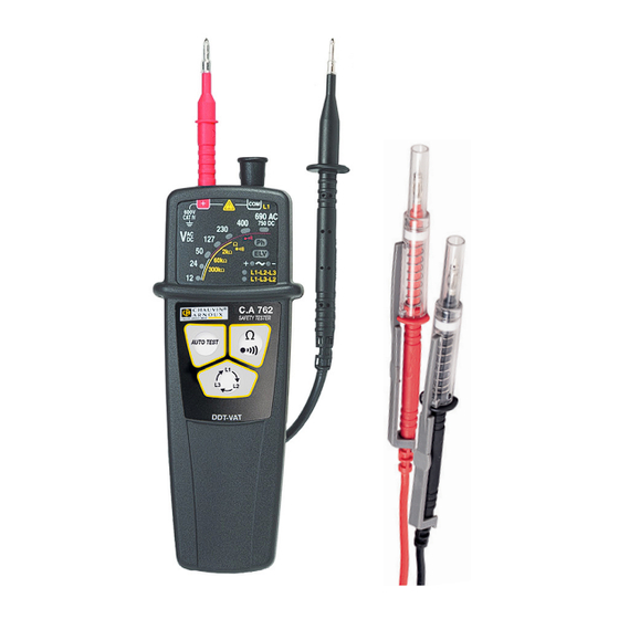
1. PRÉSENTATION 1.1. C.A 762 Cordon noir terminé par Pointe de touche rouge. une pointe de touche. B o r n e s d e raccordement. Bargraphe. Indicateur de 600V 690 AC phase. CAT IV 750 DC Ω Indicateur de Ω... - Page 5 1.2. AU DOS Lorsque l’appareil n’est pas utilisé, les pointes de touches peuvent se ranger au dos. Protection amovible. Pointe de touche rouge. Gardes. Pointe de touche noire. Trappe à pile. 1.3. C.A 762 IP2X Voir le § 2.7.
- Page 6 1.4. FONCTIONNALITÉS Le C.A 762 est un Détecteur De Tension (DDT) à voyants. Il est conforme aux prescriptions de la norme IEC 61243-3. La fonction principale du C.A 762 est la Vérification d’Absence de Tension (VAT). Il détecte les tensions dange- reuses, c’est à...
-
Page 7: Utilisation
2. UTILISATION Cet appareil est un détecteur. Les indications qu’il fournit ne doivent pas être utilisées à des fins de mesure. 2.1. AUTO TEST Avant d’utiliser le C.A 762, procédez à un auto test. Il permet de vérifier l’intégrité des cordons, le bon fonctionnement du circuit électronique et un niveau de tension suffisant pour les piles. - Page 8 „ Si un voyant sur trois s’éteint, c’est qu’il y a un problème au niveau des cordons. Vérifiez qu’ils sont correctement branchés et qu’ils sont bien en contact et appuyez à nou- veau sur le bouton AUTO TEST. Si le problème persiste, le cordon et/ou la pointe de touche doivent être remplacés.
- Page 9 Si la tension présente est : „ alternative : les voyants s’allument pour indiquer sa valeur et les voyants + (vert) et - (orange) sont allumés. 600V 690 AC CAT IV 750 DC Ω Ω Ω 300k Ω L1-L2-L3 L1-L3-L2 „...
- Page 10 2.3. INDICATION DU NIVEAU DE CONTINUITÉ Connectez la pointe de touche rouge sur la borne + et le cordon noir sur la borne COM. Placez vos mains derrière la garde de l’appareil et de la pointe de touche. Placez les pointes de touche sur l’élément à tester et main- tenez fermement le contact.
- Page 11 Si la pointe de touche est bien sur la phase, le voyant Ph (phase) clignote l’appareil émet des bips sonores. 600V 690 AC CAT IV 750 DC Ω Ω Ω 300k Ω L1-L2-L3 L1-L3-L2 Attention : ce n’est pas parce que le voyant Ph ne clignote pas qu’il n’y a pas de tension dangereuse sur la prise.
- Page 12 S’il y a un problème, c’est à dire si l’appareil ne détecte pas de changement de phase dans les 10 secondes ou si les phases ne sont pas équilibrées, il signale une erreur en émettant deux bips graves. Sinon, l’appareil indique l’ordre des phases en allumant : „...
- Page 13 Clipsez la pointe de touche rouge au dos de l’appareil et tenez la pointe de touche noire à la main. P o i n t e d e P o i n t e d e touche noire. touche rouge. Gâchettes.
- Page 14 Pour effectuer un test, appuyez sur la gâchette. Cela déverrouille la protection de la pointe qui peut coulisser. Vous pou- vez ensuite l’introduire dans une prise ou l’amener au contact de l’objet à tester. Pour utiliser l’appareil, tenez-le dans la main, tout en appuyant avec l’index sur la gâchette de la pointe de touche rouge.
-
Page 15: Caractéristiques
3. CARACTÉRISTIQUES 3.1. CONDITIONS DE RÉFÉRENCE Grandeur d’influence Valeurs de référence Température 23 ± 5 °C Humidité relative 30 à 75 % HR Tension d’alimentation 3 ± 0,1 V Fréquence du signal mesuré DC ou 45 à 65 Hz Type de signal sinusoïdal Champ électrique extérieur <... - Page 16 3.2.3. REPÉRAGE DE PHASE pour 45 Hz ≤ fréquence ≤ 65 Hz 120 V < tension < 690 V pour 16,67 Hz ≤ fréquence < 45 Hz 400 V < tension < 690 V 3.2.4. ORDRE DES PHASES Fréquence comprise entre 45 et 400 Hz. Tension comprise entre 50 et 690 V entre phases.
- Page 17 Les piles peuvent être remplacées par des accumulateurs rechargeables, mais l’autonomie sera bien moindre. 3.5. CARACTÉRISTIQUES CONSTRUCTIVES Dimensions (L x l x P) 163 x 64 x 40 mm Masse environ 210 g Cordon longueur 90 cm Indice de protection IP 65 selon IEC 60529 IK 04 selon IEC 50102 Chute...
-
Page 18: Maintenance
4. MAINTENANCE Excepté les piles, l’appareil ne comporte aucune pièce susceptible d’être remplacée par un personnel non formé et non agréé. Toute intervention non agréée ou tout remplacement de pièce par des équivalences risque de compromettre gravement la sécurité. 4.1. NETTOYAGE L’appareil doit être maintenu en parfait état de propreté. -
Page 19: Pour Commander
agréée par le fabricant ; „ une adaptation à une application particulière, non prévue par la définition du matériel ou non indiquée dans la notice de fonctionnement ; „ des dommages dus à des chocs, chutes ou inondations. 6. POUR COMMANDER Détecteur de tension C.A 762 Livré... - Page 20 ENGLISH Thank you for purchasing a C.A 762 or C.A 762 IP2X volt- age detector. For best results from your instrument: „ read these operating instructions carefully, „ comply with the precautions for use. WARNING, risk of DANGER! The operator must refer to these instructions whenever this danger symbol appears.
- Page 21 PRECAUTIONS FOR USE This device is protected against voltages up to 600V with respect to earth in measurement category IV. The protection provided by the device may be compromised if it is used other than as specified by the manufacturer and so endanger the user.
-
Page 22: Presentation
1. PRESENTATION 1.1. C.A 762 Black lead terminated Red test probe. by a test probe. Connection terminals. Bargraph. Phase indica- 600V 690 AC tor. CAT IV 750 DC Ω Hazardous Ω voltage indi- Ω 300k Ω L1-L2-L3 cator. L1-L3-L2 Polarity indi- C.A 762 SAFETY TESTER cator. - Page 23 1.2. ON THE BACK When the device is not in use, the test probes can be stowed on the back. Removable protec- tive caps. Red test probe. Guards. Black test probe. Battery compart- ment cover. 1.3. C.A 762 IP2X See §2.7.
- Page 24 1.4. FUNCTIONS The C.A 762 is a Voltage Detector with indicator lights. It complies with the requirements of standard IEC 61243-3. The main function of the C.A 762 is to test for the absence of any voltage. It detects hazardous voltages, meaning voltages exceeding the ELV (extra low voltage: 50 V or 120 V Its other functions are:...
-
Page 25: Use
2. USE This device is a detector. The indications it provides must not be used for measurement purposes. 2.1. SELF-TEST Before using the C.A 762, perform a self-test. This checks the integrity of the leads, the proper operation of the electronic circuit, and the battery voltage. - Page 26 „ If every third indicator is off, there is a problem with the leads. Check that they are correctly connected and that they are actually touching, then press the AUTO TEST button again. If the problem persists, the lead and/or the test probe must be replaced.
- Page 27 If the voltage present is: „ AC, the indicators light to indicate its value and the + (green) and - (orange) indicators light. 600V 690 AC CAT IV 750 DC Ω Ω Ω 300k Ω L1-L2-L3 L1-L3-L2 „ DC, the indicators light to indicate its value and the + in- dicator (green) or the - indicator (orange) lights to indicate the polarity.
- Page 28 2.3. CONTINUITY LEVEL INDICATION Connect the red test probe to the + terminal and the black lead to the COM terminal. Keep your hands behind the guards of the device and of the test probe. Place the test probes on the element to be tested and main- tain a firm contact.
- Page 29 If the test probe is in fact on the phase, the Ph (phase) indica- tor flashes and the device beeps. 600V 690 AC CAT IV 750 DC Ω Ω Ω 300k Ω L1-L2-L3 L1-L3-L2 Warning: if the Ph indicator is not flashing, that does not mean that there is no hazardous voltage on the outlet.
- Page 30 If there is a problem, in other words, if the device fails to detect a change of phase within 10 seconds or if the phases are not balanced, it reports an error by emitting two low- pitched beeps. Otherwise, the device indicates the phase order by lighting: „...
- Page 31 Clip the red probe tip to the back of the device and hold the black probe tip in your hand. Black probe tip. Red probe tip. Triggers. W h e r e press to un- lock the pro- tection.
- Page 32 To perform a test, press the trigger. That unlocks the protection of the probe tip, which can slide. You can then insert it in an outlet or touch the object to be tested with it. To use the device, hold it in your hand while pressing the trigger of the red probe tip with your index finger.
-
Page 33: Characteristics
3. CHARACTERISTICS 3.1. REFERENCE CONDITIONS Quantity of influence Reference values Temperature 23±5°C Relative humidity 30 to 75 % HR Supply voltage 3±0,1V Frequency of the measured signal DC or 45 to 65 Hz Type of signal sinusoidal External electric field <1V/m DC external magnetic field <40A/m... - Page 34 3.2.3. PHASE IDENTIFICATION and 45Hz≤frequency ≤65Hz 120 V <voltage<690 V 400 V <voltage<690 V and 16.67Hz≤frequency<45Hz 3.2.4. PHASE-ORDER Frequency between 45 and 400Hz. Voltage between 50 and 690 Vac between phases. Time to acquisition of the information after contact ≤1s. Retention time of the information: 10s.
- Page 35 The batteries can be replaced by rechargeable batteries, but the life between charges will be much shorter. 3.5. CHARACTERISTICS OF CONSTRUCTION Dimensions (LxWxH) 163 x 64 x 40mm Weight approximately 210g Cord length 90cm Protection class IP65 per IEC 60529 IK04 per IEC 50102 Drop 2 metres...
-
Page 36: Maintenance
4. MAINTENANCE Except for the batteries, the instrument contains no parts that can be replaced by personnel who have not been specially trained and accredited. Any unauthorized repair or replacement of a part by an “equivalent” may gravely impair safety. 4.1. -
Page 37: To Order
„ Adaptation to a particular application not anticipated in the definition of the equipment or not indicated in the user’s manual; „ Damage caused by shocks, falls, or floods. 6. TO ORDER C.A 762 voltage detector Delivered in blister pack with: „... - Page 38 DEUTSCH Sie haben einen Spannungsprüfer C.A 762 oder C.A 762 IP2X erworben und wir danken Ihnen für Ihr Vertrauen. Um die optimale Benutzung Ihres Gerätes zu gewährleisten, bitten wir Sie: „ diese Bedienungsanleitung sorgfältig zu lesen „ die Benutzungshinweise genau zu beachten. A C H T U N G , G E FA H R ! S o b a l d d i e s e s Gefahrenzeichen irgendwo erscheint, ist der Benutzer verpflichtet, die Anleitung zu Rate zu ziehen.
- Page 39 SICHERHEITSHINWEISE Geräteschutz für max. Spannung von 600V gegenüber Erde bei Anlagen der Messkategorie IV. Der Geräteschutz und damit eine gefahrlose Handhabung sind nur dann gegeben, wenn das Gerät nach Herstellerangaben verwendet wird. „ Halten Sie sich an die Messkategorie und die max. zul. Nennspannungen und -ströme.
-
Page 40: Vorstellung
1. VORSTELLUNG 1.1. C.A 762 Fest angeschlossenes Kabel Rote Tastspitze (schwarz) an Tastspitze Anschlussbuchsen Balkenanzeige Phasenan- 600V zeige 690 AC CAT IV 750 DC Ω Anzeige bei Ω Gefahren- Ω 300k Ω L1-L2-L3 spannung L1-L3-L2 Polaritäts- C.A 762 SAFETY TESTER anzeige Ω... - Page 41 1.2. RÜCKSEITE Die Tastspitzen finden an der Rückseite Platz, wenn das Gerät nicht im Einsatz ist. Stöpsel Rote Tastspitze Fingerschutz Schwarze Tastspitze Batteriefach. 1.3. C.A 762 IP2X Siehe Kapitel 2.7.
- Page 42 1.4. FUNKTIONSUMFANG C.A 762 ist ein Spannungsprüfer mit LEDs. Entspricht der IEC 61243-3-Norm. Die Hauptfunktion des C.A 762 ist die Überprüfung d e r S p a n n u n g s f re i h e i t . D a s G e r ä t e r k e n n t e i n e Gefahrenspannung, das heißt alle die Schutzkleinspannung (ELV: 50 V bzw.
-
Page 43: Verwendung
2. VERWENDUNG Es handelt sich um ein Prüfgerät, das nicht für Messeinsätze geeignet ist. 2.1. SELBSTTEST Führen Sie einen Selbsttest durch, bevor Sie den C.A 762 verwenden. Der Geräte-Selbsttest überprüft, dass die Kabel unbeschädigt sind, dass der Schaltkreis einwandfrei funktio- niert und dass die Batterien nicht zu schwach sind. - Page 44 „ Jede dritte LED leuchtet nicht: Die Leitungen sind gestört. Sie müssen überprüfen, ob die Leitungen ordentlich ange- schlossen sind und Kontakt haben. Dann den AUTO TEST wiederholen. Wenn das Problem damit nicht behoben ist, müssen Sie die Leitung und/oder die Tastspitze aus- tauschen.
- Page 45 Spannung vorhanden mit folgender Anzeige: „ Wechselspannung: Die LEDs zeigen den Wert an und die LEDs + (grün) und- (orange) leuchten. 600V 690 AC CAT IV 750 DC Ω Ω Ω 300k Ω L1-L2-L3 L1-L3-L2 „ Gleichspannung: Die LEDs zeigen den Wert an und die LED + (grün) oder die LED- (orange) leuchtet und zeigt damit die Polarität an.
- Page 46 2.3. DURCHGÄNGIGKEITSANZEIGE Stecken Sie dazu die rote Tastspitze in die +-Buchse und die schwarze Leitung in den COM-Anschluss. Fassen Sie das Gerät immer hinter dem Fingerschutz an Gerät und Tastspitze an. Halten Sie die Tastspitzen fest an den Prüfling. Ω...
- Page 47 Wenn die Tastspitze an der Phase liegt, blinkt die LED Ph (Phase). Außerdem erklingt ein akustisches BEEP-Signal. 600V 690 AC CAT IV 750 DC Ω Ω Ω 300k Ω L1-L2-L3 L1-L3-L2 Achtung: Gefahrenspannung am Stecker kann auch dann vorhanden sein, wenn die LED Ph nicht blinkt! 2.5.
- Page 48 Mögliche Fehler (das Gerät erfasst den Phasenwechsel nicht innerhalb von 10 Sekunden oder die Phasen sind nicht symmetrisch) werden mit zwei Mal tiefem Piepen gemeldet. Ansonsten zeigt das Gerät die Phasenfolge an, dabei leuchten: „ LED L1-L2-L3 mit zuerst einem tiefen und dann einem hohen Summton.
- Page 49 Klemmen Sie die rote Tastspitze hinten am Gerät an und nehmen Sie die schwarze Tastspitze in die Hand. Schwarze Rote Tastspitze. Tastspitze. Auslöser. Druckfläche zum E n t r i e g e l n d e r Schutzvorkehrung.
- Page 50 Die Auslöser drücken, um einen Test v o r z u n e h m e n . D a d u rc h w i rd d i e Schutzvorkehrung an der Spitze entrie- gelt, diese kann nun verschoben werden. Nun kann sie in eine Buchse eingeführt bzw.
-
Page 51: Technische Daten
3. TECHNISCHE DATEN 3.1. REFERENZBEDINGUNGEN Einflussgröße Bezugswerte Temperatur 23±5 °C Relative Luftfeuchte 30 bis 75% r.F. Versorgungsspannung 3±0,1 V Signalfrequenz des Messsignals DC oder 45 bis 65 Hz Signalform Sinus Elektrische Feldstärke <1 V/m Magnetfeldstärke DC <40 A/m 3.2. ELEKTRISCHE DATEN 3.2.1 SPANNUNG Nennspannungen: 12, 24, 50, 127, 230, 400, 690 V und 750 V... - Page 52 3.2.3 PHASENERKENNUNG bei 45Hz≤Frequenz ≤65Hz 120 V <Spannung<690 V 400 V <Spannung<690 V bei 16,67Hz≤Frequenz <45Hz 3.2.4 PHASENFOLGE Frequenzbereich 45 bis 400Hz. Spannungsbereich 50 bis 690 V zwischen Phasen. Erfassungsdauer ≤1s. Datenverweildauer: 10s. Max. zul. Amplituden-Unsymmetriegrad: 20% Max. zul. Oberschwingungsgehalt (Spannung): 10% Abweisung der EDF (TCC-175Hz-188Hz) Fernsignale.
- Page 53 Anstelle der Batterien können Sie auch aufladbare Akkus verwenden, wodurch die Betriebsdauer allerdings erheblich reduziert wird. 3.5. ALLGEMEINE BAUDATEN Abmessungen (L x B x T) 163 x 64 x 40mm Gewicht ca. 210g Leitung Lg. 90cm. Schutzart IP65 gem. IEC 60529 IK04 gem.
-
Page 54: Wartung
4. WARTUNG Außer den Batterien enthält das Gerät keine Teile, die von nicht ausgebildetem oder nicht zugelassenem Personal ausgewechselt werden dürfen. Jeder unzuläs- sige Eingriff oder Austausch von Teilen durch sog. „gleichwertige“ Teile kann die Gerätesicherheit schwers- tens gefährden. 4.1. REINIGUNG Halten Sie das Gerät immer tadellos sauber. -
Page 55: Bestellangaben
„ Nach Anpassungen des Geräts an besondere Anwendungen, für die das Gerät nicht bestimmt ist oder die nicht in der Bedienungsanleitung genannt sind. „ In Fällen von Stößen, Stürzen oder Wasserschäden. 6. BESTELLANGABEN Spannungsprüfer C.A 762 Lieferung in Blisterverpackung mit „... - Page 56 ITALIANO Avete appena acquistato un rivelatore di tensione C.A 762 o C.A 762 IP2X. Vi ringraziamo per la fiducia che ci avete accordato. Per ottenere le migliori prestazioni dal vostro strumento: „ Leggete attentamente il presente manuale d’uso. „ Rispettate le precauzioni d’uso. ATTENZIONE, rischio di PERICOLO! L’operatore deve consultare il presente manuale d’uso ogni volta che vedrà...
- Page 57 PRECAUZIONI D’USO Questo strumento è protetto contro le tensioni non superiori a 600V rispetto alla terra nella categoria di misura IV. Se si utilizza lo strumento in maniera non conforme alle specifiche del costruttore, la sua protezione non potrà più essere garantita e l’utente sarà...
-
Page 58: Presentazione
1. PRESENTAZIONE 1.1. C.A 762 Cavo nero con una punta Punta di contatto rossa. di contatto all’estremità. M o r s e t t i d i raccordo. Bargraph. Indicatore di 600V fase. 690 AC CAT IV 750 DC Ω Indicatore di Ω... - Page 59 1.2. SUL RETRO Quando lo strumento non è utilizzato, le punte di contatto possono sistemarsi sul retro. Protezioni amovibili. Punta di contatto rossa. Guardie. Punta di contatto nera. Vano della pila. 1.3. C.A 762 IP2X Consultare §2.7.
- Page 60 1.4. FUNZIONALITÀ Il C.A 762 è un Rivelatore Di Tensione (RDT) dotato di spie. Strumento conforme alle prescrizioni della norma EN 61243-3. La funzione principale del C.A 762 è la Verifica d’Assenza di Tensione (VAT). Esso rivela le tensioni pericolose, ossia superiori alla TMB (tensione molto bassa: 50 V o 120 V Le sue altre funzioni sono:...
-
Page 61: Utilizzo
2. UTILIZZO Questo strumento è un rivelatore: le indicazioni che fornisce non vanno utilizzate a fini di misura. 2.1. AUTO-TEST Prima di utilizzare il C.A 762, procedete ad un auto test che permette di verificare l’integrità dei cavi, il corretto fun- zionamento del circuito elettronico e un livello di tensione sufficiente per le pile. - Page 62 „ Se una spia su tre si spegne, ciò significa che c’è un pro- blema a livello dei cavi. Verificate che siano correttamente allacciati e bene in contatto dopodiché premete di nuovo il bottone AUTO TEST. Se il problema persiste, il cavo e/o la punta di contatto vanno sostituiti.
- Page 63 Se la tensione presente è: „ alternata: le spie si accendono per indicare il suo valore e le spie + (verde) e - (arancione) sono accese. 600V 690 AC CAT IV 750 DC Ω Ω Ω 300k Ω L1-L2-L3 L1-L3-L2 „...
- Page 64 2.3. INDICAZIONE DEL LIVELLO DI CON- TINUITÀ Collegate la punta di contatto rossa al morsetto + e il cavo nero al morsetto COM. Mettete le mani dietro la guardia dello strumento e della punta di contatto. Posizionate le punte di contatto sull’elemento da testare e mantenete fermamente il contatto.
- Page 65 Posizionate le punte di contatto sull’elemento da testare e mantenete fermamente il contatto. Se la punta di contatto è correttamente sulla fase, la spia Ph (fase) lampeggia e lo strumento emette vari bip sonori. 600V 690 AC CAT IV 750 DC Ω...
- Page 66 In caso di problema, ossia se lo strumento non rivela cambiamenti di fase entro 10 secondi o se le fasi non sono equilibrate, l’errore viene segnalato da due bip gravi. Altrimenti, lo strumento indica l’ordine delle fasi accendendo: „ La spia L1-L2-L3 e emettendo un bip grave seguito da un bip acuto „...
- Page 67 Clipsate la punta di contatto rossa sul retro dello strumento e tenete in mano la punta di contatto nera. Punta di con- Punta di con- tatto nera. tatto rossa. Grilletti. Z o n e d ’ a p - p o g g i o p e r sbloccare la protezione.
- Page 68 Per effettuare un test, premete il grilletto: sbloccherete così la protezione della punta che può scorrere. Potete in seguito introdurla in una presa o metterla in con- tatto con l’oggetto da testare. Per utilizzare lo strumento, tenetelo in mano, premendo sempre con l’indice il grilletto della punta di contatto rossa.
-
Page 69: Caratteristiche
3. CARATTERISTICHE 3.1. CONDIZIONI DI RIFERIMENTO Grandezza d’influenza Valori di riferimento Temperatura 23 ± 5 °C Umidità relativa 30 a 75 % UR Tensione d’alimentazione 3 ± 0,1 V Frequenza del segnale misurato DC o 45 a 65 Hz Tipo di segnale sinusoidale Campo elettrico esterno <... - Page 70 3.2.3. IDENTIFICAZIONE DI FASE per 45Hz≤ frequenza ≤65Hz 120 V <tensione<690 V 400 V <tensione<690 V per 16,67Hz≤ frequenza <45Hz 3.2.4. ORDINE DELLE FASI Frequenza compresa fra 45 e 400Hz. Tensione compresa fra 50 e 690 V tra fasi. Tempi d’acquisizione delle informazioni dopo contatto ≤1s. Tempo di ritenzione dell’informazione: 10s.
- Page 71 E’ possibile sostituire le pile con accumulatori ricaricabili ma l’autonomia sarà nettamente inferiore. 3.5. CARATTERISTICHE COSTRUTTIVE Dimensione (L x Am x Al) 163 x 64 x 40mm Peso circa 210 g Cavo lunghezza 90cm Indice di protezione IP65 secondo EN 60529 IK04 secondo EN 50102 Caduta 2 metri.
-
Page 72: Manutenzione
4. MANUTENZIONE Tranne le pile, lo strumento non comporta pezzi sostituibili da personale non formato e non autorizzato. Qualsiasi intervento non autorizzato o qualsiasi sostitu- zione di pezzi con pezzi equivalenti rischia di compro- mettere gravemente la sicurezza. 4.1. PULIZIA Lo strumento deve essere mantenuto in perfetto stato di pulizia. -
Page 73: Per Ordinare
„ Lavori effettuati sullo strumento da una persona non auto- rizzata dal fabbricante; „ Adattamento ad un’applicazione particolare, non prevista dalla progettazione dello strumento o non indicata nel manuale di funzionamento; „ Danni dovuti a urti, cadute, inondazioni. 6. PER ORDINARE Rivelatore di tensione C.A 762 Fornito sotto blister con: „... - Page 74 ESPAÑOL Usted acaba de adquirir un detector de tensión C.A 762 o C.A 762 IP2X y le agradecemos la confianza que ha depo- sitado en nosotros. Para conseguir las mejores prestaciones de su instrumento: „ lea atentamente este manual de instrucciones, „...
- Page 75 PRECAUCIONES DE USO Este instrumento está protegido contra tensiones que no supe- ran 600 V con respecto a la tierra en la categoría de medida IV. La protección garantizada por el instrumento puede verse alterada si el mismo se utiliza de forma no especificada por el fabricante y poner así...
-
Page 76: Presentación
1. PRESENTACIÓN 1.1. C.A 762 Cable negro acabado Punta de prueba roja. por una punta de prueba. Bor nes de conexión. Barra analó- gica. Indicador de 600V fase. 690 AC CAT IV 750 DC Indicador de Ω Ω tensión peli- Ω... - Page 77 1.2. EN EL DORSO Cuando no se utiliza el instrumento, las puntas de prueba pueden guardarse en el dorso. Protecciones amo- vibles. Punta de prueba roja. Protecciones. Punta de prueba negra. Tapa de las pilas. 1.3. C.A 762 IP2X Véase §2.7.
- Page 78 1.4. FUNCIONES El C.A 762 es un detector de tensión (DDT) con pilotos. Cumple con los requisitos de la norma IEC 61243-3. La función principal del C.A 762 es la verificación de ausencia de tensión (VAT). Detecta las tensiones peligrosas, es decir superior a la MBT (muy baja tensión: 50 V o 120 V Sus demás funciones son:...
-
Page 79: Utilización
2. UTILIZACIÓN Este instrumento es un detector. Las indicaciones que pro- porciona no deben utilizarse para realizar medidas. 2.1. AUTO TEST Antes de utilizar el C.A 762, efectúe un auto-test. Permite verificar el buen estado de los cables, el correcto funcionamiento del circuito electrónico y un nivel de tensión suficiente para las pilas. - Page 80 „ Si se apaga un piloto de cada tres, es que hay un proble- ma con los cables. Compruebe que estén correctamente conectados y que estén en contacto y presione de nuevo el botón AUTO TEST. Si el problema persiste, se debe cambiar el cable y/o la punta de prueba.
- Page 81 Si la tensión presente es: „ alterna: los pilotos se encienden para indicar su valor y los pilotos + (verde) y - (naranja) están encendidos. 600V 690 AC CAT IV 750 DC Ω Ω Ω 300k Ω L1-L2-L3 L1-L3-L2 „ continua: los pilotos se encienden para indicar su valor y el piloto + (verde) o el piloto - (naranja) se enciende para indicar la polaridad.
- Page 82 2.3. INDICACIÓN DEL NIVEL DE CONTI- NUIDAD Conecte la punta de prueba roja al borne + y el cable negro al borne COM. Posicione las manos detrás de la protección del instrumento y de la punta de prueba. Coloque las puntas de prueba sobre el elemento a probar y mantenga firmemente el contacto.
- Page 83 Coloque la punta de prueba sobre el elemento a probar y mantenga firmemente el contacto. Si la punta de prueba está en contacto con la fase, el piloto Ph (fase) parpadea y el instrumento emite señales acústicas. 600V 690 AC CAT IV 750 DC Ω...
- Page 84 Si existe algún problema, es decir si el instrumento no de- tecta ningún cambio de fase en 10 segundos o si las fases no están equilibradas, indica un error emitiendo dos señales acústicas graves. Si no, el instrumento indica el orden de las fases encendiendo: „...
- Page 85 Enganche la punta de prueba roja al dorso del instrumento y sujete la punta de prueba negra con la mano. Punta de prueba Punta de prue- negra. ba roja. Gatillos. Z o n a s a p o y o p a r a desbloquear la protección.
- Page 86 Para realizar una prueba, presione el gatillo. Esto desbloquea la protección de la punta que puede deslizarse. Puede usted entonces introducirla en una toma o ponerla en contacto con el objeto a probar Para utilizar el instrumento, sujételo en la mano, mientras pre- siona el gatillo de la punta de prueba roja con el dedo índice.
-
Page 87: Características
3. CARACTERÍSTICAS 3.1. CONDICIONES DE REFERENCIA Magnitud de influencia Valores de referencia Temperatura 23 ± 5 °C Humedad relativa 30 a 75 % HR Tensión de alimentación 3 ± 0,1 V Frecuencia de la señal medida DC o 45 a 65 Hz Tipo de señal sinusoidal Campo eléctrico exterior... - Page 88 3.2.3. IDENTIFICACIÓN DE FASE para 45 Hz ≤ frecuencia ≤ 65 Hz 120 V < tensión < 690 V para 16,67 Hz ≤ frecuencia < 45 Hz 400 V < tensión < 690 V 3.2.4. ORDEN DE LAS FASES Frecuencia comprendida entre 45 y 400 Hz. Tensión comprendida entre 50 y 690 V entre fases.
- Page 89 Las pilas pueden sustituirse por acumuladores recargables, pero la autonomía será bastante menor. 3.5. CARACTERÍSTICAS CONSTRUCTIVAS Dimensiones (L x An x Al) 163 x 64 x 40 mm Peso aproximadamente 210 g Cable longitud 90 cm Índice de protección IP65 según IEC 60529 IK04 según IEC 50102 Caída 2 metros.
-
Page 90: Mantenimiento
4. MANTENIMIENTO Salvo las pilas, el instrumento no contiene ninguna pieza que pueda ser sustituida por un personal no for- mado y no autorizado. Cualquier intervención no autori- zada o cualquier pieza sustituida por piezas similares pueden poner en peligro seriamente la seguridad. 4.1. -
Page 91: Para Pedidos
„ Adaptación a una aplicación particular, no prevista en la definición del equipo y no indicada en el manual de instrucciones; „ Daños debidos a golpes, caídas o inundaciones. 6. PARA PEDIDOS Detector de tensión C.A 762 Suministrado en blíster con: „...
Need help?
Do you have a question about the Chauvin Arnoux C.A 762 and is the answer not in the manual?
Questions and answers