Table of Contents
Advertisement
Quick Links
Advertisement
Table of Contents

Related Manuals for Chamberlain LiftMaster LM750EVGB-1


Summary of Contents for Chamberlain LiftMaster LM750EVGB-1
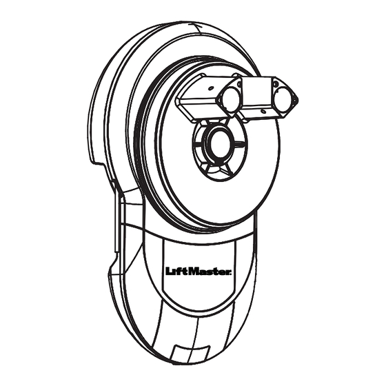
- Page 1 LM750EVGB-1 Rolling Garage Door Opener Installation and Operating Instructions Chamberlain GmbH Saar-Lor-Lux-Str. 19 66115 Saarbrücken Germany WEEE-Reg.Nr. Germany DE66256568 www.liftmaster.eu info@liftmaster.eu 114A5875A2 2024, all rights reserved...
-
Page 2: Table Of Contents
TABLE OF CONTENTS These instructions are original operting instructions according to Supply of Machinery (Safety) Regulations 2008 SI 2008 No. 1597 / EC Directive 2006/42/EC. Please read through all of the instructions carefully, as they contain important information about the product. Please pay attention to and follow the instructions provided, particularly the safety instructions and warnings. -
Page 3: Safety Instructions And Intended Use
WARNING! Start by Reading These Important Safety Instructions General safety guidelines Before you begin the installation: Please read the operating instructions and especially the precautions. Keep the manual for future reference and pass it on to a possible subsequent owner. The following symbols are placed in front of instructions to avoid personal injury or property damage. -
Page 4: Carton Inventory
Any improper use of the drive could increase the risk of accidents. The manufacturer assumes no liability for such usage. Only the original accessories of Chamberlain may be connected to the drive. With this drive, door must comply with the currently valid international and country-specific standards, guidelines,... -
Page 5: Control Panel
CONTROL PANEL #1. Terminal Block: used for external accessories (see chart below). Function Colour Polarity Comment Push button Dry contact input for push button wired wall controls Common White Common terminal for push button, obstruction detection beams & accessory power Common White Common terminal for push button, obstruction detection beam &... -
Page 6: Testing The Door
TESTING THE DOOR Complete the following test to ensure your door is well balanced, and not sticking or binding: • Disable all locks and remove any ropes connected to the garage door. • Lift the door to about halfway and then release it. The door should remain spring balanced. -
Page 7: Pinning The Door
PINNING THE DOOR Note: A ballooning door may delay the safety reversal Free curtain Ballooning Add fasteners here response and can compromise garage door security. • To remedy any ballooning, insert the supplied self tapping metal screws into where the curtain leaves the roll. Secure these through the curtain into the drum wheel at each end of the roll. -
Page 8: Attaching Extension Poles (If Required)
Extension pole ATTACHING EXTENSION POLES (IF REQUIRED), Drive leg when the drum wheel is positioned deeper inside the door curtain. • Insert the extension poles into the drive legs. • Align the holes on the extension poles with the holes on the drive legs. -
Page 9: Installation Procedure
INSTALLATION PROCEDURE Do not allow people to walk under or around the door during the installation process as serious injury can occur. NOTE: The opener can be installed on either side of the door. The following instructions are for RIGHT HAND INSTALLATIONS (as illustrated i.e. Rope inside the garage looking out). -
Page 10: Setting The Limits For Right Or Left Hand Operation And Force
SETTING THE LIMITS FOR RIGHT OR LEFT HAND OPERATION AND FORCE Travel limits set how far your door goes up and down. Your opener must also be configured for right or left hand installation. If not the door will rotate in the reverse direction. Program Buttons: The Control Panel diagram in section 4 (page 5) identifies the Control Buttons and LED layout. -
Page 11: Testing The Safety Reverse System
TESTING THE SAFETY REVERSE SYSTEM After installing the operator on the door, the force measurement of the operator must be checked according to UK: BS EN 13241/BS EN 12453; EU: EN 13241/EN 12543 with a force measurement device and an obstacle detection test must be performed. 40 mm Operate the door in the down direction. -
Page 12: Install The Obstruction Detection Beams/ The Protector Systemtm (Optional Accessory)
INSTALL THE OBSTRUCTION DETECTION BEAMS/ THE PROTECTOR SYSTEM (OPTIONAL ACCESSORY) After installing and adjusting the door opener, photocells can be installed. The installation instructions are included with the photocells. The optional photocells ensure that the door is open, or IR Beams must be installed remains open, if people, especially young children, are in the to detect a 100 mm high door area. -
Page 13: Audible Beep (Optional)
AUDIBLE BEEP (OPTIONAL) The LM750EVGB has been factory set for an audible “BEEP”. The Audible beep can be turned OFF by using the following method. Flash x2 • Start with the door fully CLOSED. AUDIBLE BEEP • Press and Hold both “S” and “DN” buttons for 3 seconds. -
Page 14: Program Transmitters To The Opener Light
WIRELESS PROGRAMMING (REMOTE ACCESSORIES) NOTE: The transmitters supplied with your opener are preprogrammed by the factory (Top button). Activate the opener only when door is in full view, free of obstruction and properly adjusted. No one should enter or leave the garage while the door is in motion. -
Page 15: Myq Gateway / Standby Mode (Optional)
PROGRAM INTERNET GATEWAY myQ 828EV Using the S button on the garage door opener 1. Connect the ethernet cable to the Liftmaster Internet Gateway and the router 2. Connect power to the Liftmater Internet Gateway. 3. Download the free myQ App from App Store or Router Google Play Store and create an account.If you Power supply unit... -
Page 16: Typical Wiring Diagram Lm750Evgb Information For Service Personnel
TYPICAL WIRING DIAGRAM LM750EVGB Information for Service Personnel green (1) grey (2) white (3,4) red (5) External Receiver 24 V dc max. 10 m Wired Wall Button Obstruction Detection Beams... - Page 17 OPERATION OF YOUR OPENER CARE OF YOUR OPENER When properly installed, your opener will operate with minimal maintenance. Your opener can be activated by any of the following The opener does not require additional lubrication. devices: Limit and Force Settings: These settings must be checked and properly set when the opener is installed.
-
Page 18: Replace Batteries In Remotes
REPLACE BATTERIES IN REMOTES Battery of the remote control: The batteries in the remote have a long life. If the transmission range decreases, the batteries should be replaced. Batteries are not covered by the warranty. To prevent SERIOUS INJURY OR DEATH: observe the following instructions for the battery •... -
Page 19: Troubleshooting
TROUBLESHOOTING 11. The opener will not operate due to a power failure: • Use the manual release handle to disconnect the door. The door can be 1. The opener will not operate from either the opened and closed manually. When power is restored, re-engage the UP/DOWN activation button or the transmitters: opener to operate it via a transmitter. -
Page 20: Diagnostic Chart
The radio equipment type (TX4EVF, 128EV) is in compliance with Directive 2014/53/EU and for UK with Radio Equipment Regulation SI 2017 No. 1209. The full text of the EU declaration of conformity is available at the following internet address: https://doc.chamberlain.de/...
Need help?
Do you have a question about the LiftMaster LM750EVGB-1 and is the answer not in the manual?
Questions and answers