Table of Contents
Advertisement
Available languages
Available languages
de
en
fr
Notice de montage et de commande pour entraînements de portes de garage LM60EVS, LM80EVS, LM100EVS, LM130EVS
nl
Montage- en bedieningshandleiding voor garagepoortaandrijvingen LM60EVS, LM80EVS, LM100EVS, LM130EVS
da
no
sv
pl
cs
sl
Istruzioni d'uso e di montaggio per gli automatismi delle porte garage modello LM60EVS, LM80EVS, LM100EVS, LM130EVS
it
Instrucciones de montaje y manejo para accionamientos de puertas de garaje LM60EVS, LM80EVS, LM100EVS, LM130EVS
es
hu
fi
sk
Руководство по монтажу и эксплуатации на приводы гаражных ворот LM60EVS, LM80EVS, LM100EVS, LM130EVS
rus
hr
Instrucţiuni de montaj şi utilizare pentru sistem de acţionare pentru porţi de garaj LM60EVS, LM80EVS, LM100EVS, LM130EVS
ro
is
Montage- und Bedienungsanleitung für Garagentorantriebe LM60EVS, LM80EVS, LM100EVS, LM130EVS
Assembly- and operating instructions for Garage Door Opener LM60EVS, LM80EVS, LM100EVS, LM130EV
Monterings- og betjeningsvejledning for garageportautomatik LM60EVS, LM80EVS, LM100EVS, LM130EVS
Monterings- og bruksanvisning for garasjeportmotorer LM60EVS, LM80EVS, LM100EVS, LM130EVS
Monterings- och driftinstruktioner för garageportsöppnare LM60EVS, LM80EVS, LM100EVS, LM130EVS
Instrukcja montażu i obsługi napędów bram garażowych LM60EVS, LM80EVS, LM100EVS, LM130EVS
Návod na montáž a obsluhu pro pohony garážových vrat LM60EVS, LM80EVS, LM100EVS, LM130EVS
Navodila za montažo in upravljanje pogona garažnih vrat LM60EVS, LM80EVS, LM100EVS, LM130EVS
Szerelési és használati útmutató LM60EVS, LM80EVS, LM100EVS, LM130EVS garázsajtó-hajtószerkezetekhez
Asennus- ja käyttöohje autotallinoven käyttölaitteille LM60EVS, LM80EVS, LM100EVS, LM130EVS
Návod na montáž a obsluhu pre pohony garážovej brány LM60EVS, LM80EVS, LM100EVS, LM130EVS
Upute za montažu i uporabu pogona za garažna vrata LM60EVS, LM80EVS, LM100EVS, LM130EVS
Uppsetningar- og notkunarleiðbeiningar fyrir LM60EVS, LM80EVS, LM100EVS, LM130EVS bílskúrshurðaopnare
®
LM60EVS, LM80EVS, LM100EVS, LM130EVS
Advertisement
Chapters
Table of Contents

Related Manuals for Chamberlain LM60EVS


Summary of Contents for Chamberlain LM60EVS
- Page 1 Руководство по монтажу и эксплуатации на приводы гаражных ворот LM60EVS, LM80EVS, LM100EVS, LM130EVS Upute za montažu i uporabu pogona za garažna vrata LM60EVS, LM80EVS, LM100EVS, LM130EVS Instrucţiuni de montaj şi utilizare pentru sistem de acţionare pentru porţi de garaj LM60EVS, LM80EVS, LM100EVS, LM130EVS Uppsetningar- og notkunarleiðbeiningar fyrir LM60EVS, LM80EVS, LM100EVS, LM130EVS bílskúrshurðaopnare...
-
Page 2: Table Of Contents
1 Allgemeine Sicherheitshinweise ......2 27 Bedienung des Torantriebs ......8 2 Bestimmungsgemäßer Gebrauch . -
Page 3: Allgemeine Sicherheitshinweise
ACHTUNG! BITTE ZUNÄCHST FOLGENDE SICHERHEITSHINWEISE LESEN! Allgemeine Sicherheitshinweise Bevor Sie mit der Montage beginnen: Lesen Sie bitte die Bedienungsanleitung und vor allem die folgenden Sicherheitshinweise. Bewahren Sie die Anleitung zum Nachlesen auf und geben Sie sie an einen möglichen nachfolgenden Eigentümer weiter. Die folgenden Symbole stehen vor Hinweisen zur Vermeidung von Personen- oder Sachschäden. -
Page 4: Bestimmungsgemäßer Gebrauch
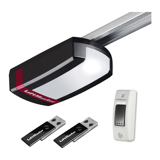
Lichtschranke, The Protector System™ , erforderlich. 1. Antriebskopf 8. Gebogener Torarm Ihr Händler hilft Ihnen gerne weiter. 2. Handsender 9. Befestigungsbügel Spezialtorarm – The Chamberlain Arm™ für Tore von Typ B und D. 3. Schienenhalterung 10. Abhängeeisen 4. Zubehörbeutel 11. Schiene Vorbereitung Teileübersicht (Schiene):... -
Page 5: Montage Des Torantriebs
Montage des Torantriebs Einbau des Torantriebs 12.1 Wichtige Anweisungen für sichere Montage. Mitte des Garagentores festlegen Alle Montageanweisungen befolgen. Falsche Montage Bei Überkopfarbeiten muss zum Schutz der Augen eine Schutzbrille kann zu ernsthaften Verletzungen führen. getragen werden. Zur Vermeidung einer Beschädigung des Tores sind Schiene zusammenbauen alle vorhandenen Sperren / Schlösser zu deaktivieren. -
Page 6: Torantrieb Aufhängen
Torarm am Laufwagen befestigen Torantrieb aufhängen Der gerade Torarm ist bereits vormontiert. Durch Ziehen am roten Griff Tor ganz öffnen, Torantrieb auf dem Tor ablegen (Abb. A). wird der Laufwagen vom Zahnriemen entriegelt und kann per Hand bewegt Ein Stück Holz / Karton an der markierten Stelle (X) unterlegen. werden. -
Page 7: Installation Einer Lichtschranke
PROGRAMMIERTASTEN: Installation einer Lichtschranke Die Programmiertasten befinden sich unter der abnehmbaren Abdeckung (Optionales Zubehör) auf der Rückseite des Antriebs (siehe Abb. 24). Nach Installation und Einstellung des Torantriebs kann eine Lichtschranke installiert werden. Die Installationsanleitung ist im Lieferumfang der Licht- 1. -
Page 8: Automatischen Sicherheitsrücklauf Testen
1. Gelbe Einlerntaste am Antrieb drücken und loslassen. Beschreibung der Funktion: Die Einlernanzeige leuchtet 30 Sekunden lang ohne Unterbrechung (1). Die Chamberlain Sicherheitslichtschranke muss nach EN60335-1-95 2. Halten Sie eine Taste des Handsenders, mit der Sie künftig Ihr installiert sein. - Page 9 Deaktivieren: Funkgesteuertes Schlüsselloses Zugangssystem (nur mit 747EV Funkcodeschloss): Drücken Sie gleichzeitig die rechteckige Programmiertaste und die AB Taste bis die Antriebsbeleuchtung blinkt. Betreiben Sie das Tor mit einem persönlichen 4-stelligen Zahlencode. Temporärer Zugang (nur mit 747EV Funkcodeschloss): Um die Programmierung abzuschliessen, drücken Sie die rechteckige Programmiertaste.
-
Page 10: Bedienung Des Torantriebs
Hinweisschilder befestigen Bedienung des Torantriebs (Abb. 28) Automatisches Öffnen / Schließen des Tores: Reinigung und Wartung Mit Hilfe folgender Geräte kann der Torantrieb aktiviert werden: • Handsender: Taste drücken, bis sich das Tor in Bewegung setzt. Vor jeder Pflege, Reinigung und entsprechenden •... -
Page 11: Batterien Des Handsenders Austauschen
Häufig gestellte Fragen 30.2 Batterien des Handsenders tauschen 1. Torantrieb lässt sich mit Funksteuerung nicht anschalten: Batterie des Handsenders: • Ist der Antrieb an die Stromversorgung angeschlossen? Schaltet sich Die Batterien im Handsender sind äußerst langlebig. Verringert sich der eine an die Steckdose angeschlossene Lampe nicht an, Sicherung oder Sendebereich, müssen die Batterien ausgetauscht werden. - Page 12 6. Das Tor öffnet sich zwar, schließt jedoch nicht: 14. Schiene am Antrieb biegt sich: • Sofern installiert, die Lichtschranke überprüfen. Blinkt die LED an der • Tor ist schwer, sehr schwer, schwergängig oder in schlechtem Zustand. Lichtschranke, muss die Ausrichtung korrigiert werden. Rufen Sie einen Fachmann.
-
Page 13: Diagnose Tabelle
DIAGNOSE TABELLE Der Garagentorantrieb ist mit einer Diagnosefunktion ausgestattet. Die AUF und AB Tasten an der Steuerung blinken. Zählen Sie die Anzahl der “Blinks” der jeweiligen Taste zwischen zwei Blinkpausen. Es wird immer das letzte aufgetretene Ereignis angezeigt. ANZEIGE SYMPTOM LÖSUNG AUF Taste AB Taste... -
Page 14: Optionales Zubehör
ANZEIGE SYMPTOM LÖSUNG AUF Taste AB Taste Anschluss 1+2 für den Wandschalter Kabelfehler in der Zuleitung. Kabel nicht neben 230 Volt oder im selben Rohr führen. ist kurzgeschlossen für länger als 4 Testweise neues Kabel verlegen. Sekunden. Spannung zu niedrig. Die Stromspannung ist/war zu niedrig. -
Page 15: Technische Daten
Tormaße und -gewicht Technische Daten Eingangsspannung......220-240 VAC, 50/60 Hz Schwingtore LM60EVS LM80EVS LM100EVS LM130EVS max. Breite (mm) Max. Zugkraft ........650 N (LM60), 800 N (LM80), 3250 5000 5000 5000 1000 N (LM100), 1300 (LM130) max. Höhe (mm) 2260 2300 2300... - Page 16 1 General safety guidelines ......1 28 Attach safety labels ........8 2 Intended use .
-
Page 17: General Safety Guidelines
WARNING! Start by Reading These Important Safety Instructions General safety guidelines Before you begin the installation: Please read the operating instructions and especially the precautions. Keep the manual for future reference and pass it on to a possible subsequent owner. The following symbols are placed in front of instructions to avoid personal injury or property damage. -
Page 18: Intended Use
Note: The numbering only applies to the corresponding section. required. See your dealer. C. Sectional Door with Curved Track – See 20B – connect door arm. D. Canopy door – Special door arm (E, The Chamberlain Arm™) and the Parts overview (Drivehead): Protector System™ required. See your dealer. -
Page 19: Assembly Of The Door Opener
Assembly of the door opener Installation of the opener 12.1 Important instructions for a safe installation. Centre of the garage door Observe all assembly instructions. Eye protection goggles should be worn for overhead work. Incorrect installation can cause serious injury. All available barriers / locks should be deactivated to avoid damage to the door. -
Page 20: 114 Attaching Drive To Header
Attaching drive to header Attaching door arm on the trolley It may be necessary to place the drive temporarily higher, so The straight door arm is already pre-assembled. that the rail does not hit the springs in sectional doors. Pulling the red handle the trolley will be released and can be moved The drive must either be well supported (ladder) or held firmly by manually. -
Page 21: 121 Connecting The Opener
1. Press and hold the square Adjustment Button until the UP Button begins Installation of photocells (Optional accessory) to flash. After installing and adjusting the door opener, photocells can be installed. 2. Press and hold the UP Button until the door is in the desired UP position. The installation instructions are included with the photocells. -
Page 22: Test The Safety Reverse System
Program the Receiver to Match Additional Remote Controls: Instructions for Auto-Close Feature Description of feature: The Chamberlain Safety IR Sensors must be Using the yellow round button installed (required by EN60335-1-95). - Page 23 One button close feature (requires 747EV wireless keypad): Troubleshooting: Without having the access code the door can be closed from any Question: Operator will not work anymore without IR sensor. position (not opened). Solution: Correct. IR sensors are mandatory once connected. A full logic board reset is required.
-
Page 24: Operation Of The Door Opener
Attach warning labels Operation of the door opener (see fig. 28) Automatic opening / closing of the door: Cleaning and maintenance The door opener can be operated using the following devices: • Remote control: Press the button until the door starts to move. Before any maintenance, cleaning and related maintenance work, the mains supply plug should be pulled out. -
Page 25: Replace Batteries Of The Remote Control
Frequently asked questions 30.2 Replace batteries of the remote control 1. Door opener doesn’t work with remote control: Battery of the remote control: • Is the opener connected to the power supply? If a lamp connected The batteries in the remote have an extremely long life. to the power socket does not turn on, check fuse or circuit breaker. - Page 26 6. The door opens, but does not close: 15. The opener „runs“ (audible turning of motor) but the carriage does • If installed, the photocells should be checked. If the LED at the photocells not move: blink, the alignment should be checked. •...
-
Page 27: Diagnostic Chart
Diagnostic Chart Your garage door opener is programmed with self-diagnostic capabilities. The UP and DOWN arrows on the garage opener flash the diagnostic codes. DIAGNOSTIC CODE SYMPTOM SOLUTION Up Arrow Down Arrow Flash(es) Flash(es) The garage door opener will not Safety sensors are not installed, connected or wires may be cut. -
Page 28: Optional Accessories
DIAGNOSTIC CODE SYMPTOM SOLUTION Up Arrow Down Arrow Flash(es) Flash(es) Terminal 1+2 for wall control is short- Check wiring for push button if button is stuck and activated permanently. Remove ened longer than 4 seconds wiring from terminal 1+2 on operator as test. Do not run push button wires next to high voltage wiring or in same conduit. -
Page 29: Specifications
Door dimensions und -weight Specifications Input Voltage....220-240 VAC, 50/60 Hz One piece doors LM60EVS LM80EVS LM100EVS LM130EVS Max. Pull Force ....650 N (LM60), 800 N (LM80), 1000 N (LM100) 1300 N (LM130) max. width (mm) 3250 5000 5000 5000 Standby Power max.
Need help?
Do you have a question about the LM60EVS and is the answer not in the manual?
Questions and answers