Table of Contents
Advertisement
Quick Links
Advertisement
Table of Contents

Related Manuals for Supermicro H13SRH


Summary of Contents for Supermicro H13SRH
- Page 1 H13SRH USER’S MANUAL Revision 1.0...
- Page 2 Super Micro Computer, Inc. ("Supermicro") reserves the right to make changes to the product described in this manual at any time and without notice. This product, including software and documentation, is the property of Supermicro and/or its licensors, and is supplied only under a license.
- Page 3 About This Manual This manual is written for system integrators, IT technicians, and knowledgeable end users. It provides information for the installation and use of the H13SRH motherboard. About This Motherboard The Supermicro H13SRH supports a single AMD Ryzen™ Threadripper™ PRO 7000 WX- Series processor in Socket sTR5 (LGA-4844) with a thermal design power (TDP) of up to 350 W.
-
Page 4: Contacting Supermicro
San Jose, CA 95131 U.S.A. Tel: +1 (408) 503-8000 Fax: +1 (408) 503-8008 Email: marketing@supermicro.com (General Information) Sales-USA@supermicro.com (Sales Inquiries) Government_Sales-USA@supermicro.com (Gov. Sales Inquiries) support@supermicro.com (Technical Support) RMA@supermicro.com (RMA Support) Webmaster@supermicro.com (Webmaster) Website: www.supermicro.com Europe Address: Super Micro Computer B.V. -
Page 5: Table Of Contents
Preface Table of Contents Contacting Supermicro ......................4 Chapter 1 Introduction 1.1 Quick Reference .........................10 Quick Reference Table ......................11 Motherboard Features .......................12 Motherboard Block Diagram .....................14 1.2 Processor and Chipset Overview ..................15 Features Supported ......................15 1.3 Special Features ........................15 Recovery from AC Power Loss ..................15 1.4 System Health Monitoring ....................15... - Page 6 Preface 2.4 Memory Support and Installation ..................30 Memory Support ........................30 DIMM Module Population ....................31 DIMM Installation ......................32 DIMM Removal .........................32 2.5 M.2 Installation ........................33 M.2 Heatsink Installation (Optional) ..................33 2280 M.2 Device Installation .....................34 22110 M.2 Device Installation ...................35 2.6 Connectors .........................36 Power Connections ......................36 Headers ..........................36 2.7 Jumper Settings .........................37...
- Page 7 Chapter 4 BIOS 4.1 Introduction .........................46 Starting the Setup Utility ....................46 4.2 Main Setup .........................47 4.3 Advanced Setup Configurations ..................49 4.4 BMC ............................81 4.5 Event Logs .........................84 4.6 Security ..........................86 4.7 Boot ...........................89 4.8 Save & Exit .........................90 Appendix A Software Appendix B Standardized Warning Statements...
-
Page 8: Chapter 1 Introduction
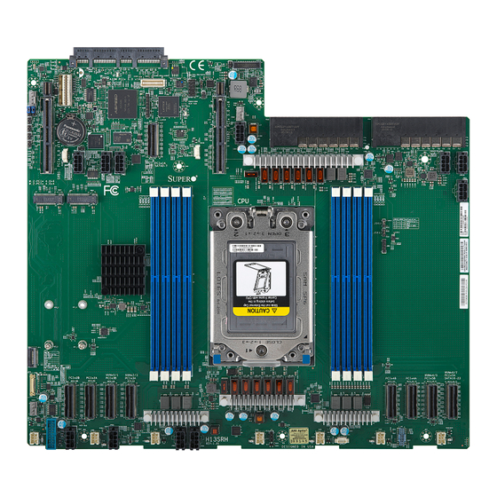
Chapter 1 Introduction Congratulations on purchasing your computer motherboard from an industry leader. Supermicro motherboards are designed to provide you with the highest standards in quality and performance. Important Links For your motherboard to work properly, please follow the links below to download all necessary drivers/utilities and the user’s manual for your server. - Page 9 Chapter 1: Introduction Figure 1-1. H13SRH Motherboard Image Note: All graphics shown in this manual were based upon the latest PCB revision available at the time of publication of the manual. The motherboard you received may or may not look...
-
Page 10: Quick Reference
JPWR6 FAN3 JPWR8 JNVI2C1 JPWR7 FAN4 JPWR5 FAN6 Figure 1-2. H13SRH Layout Notes: • Components not documented are for internal testing only. • Chapter 2 for detailed information on jumpers, I/O ports. • Use only the correct type of onboard CMOS battery as specified by the manufacturer. To... -
Page 11: Quick Reference Table
Onboard Battery FAN1-FAN7 System Fan FAN8-FAN10 12 V 4-pin Power Connector (for Optional System Fan) JAIOM1 Supermicro® Advanced I/O Module (AIOM PCIe 5.0 x16) Slot JAIOM2SB1 AIOM Sideband Signal JFP1, JFP2 Front Control Panel Headers 1 and 2 JIO1 Front BMC and Onboard VGA / USB / LAN Module Connector... -
Page 12: Motherboard Features
Chapter 1: Introduction Motherboard Features • Single AMD Ryzen™ Threadripper™ PRO 7000 WX-Series Processor in one socket LGA-4844 (socket sTR5) with a thermal design power (TDP) of up to 350 W. Note: Only Windows 11, version 22H2 offers up to 96 cores and 192 threads. Memory •... - Page 13 For proper thermal management, please check the chassis and heatsink specifications. Note 2: For IPMI configuration instructions, please refer to the Embedded IPMI Configuration User's Guide available at https://www.supermicro.com/support/manuals/. Note 3: For proper BMC configuration, please refer to https://www.supermicro.com/products/...
-
Page 14: Motherboard Block Diagram
Chapter 1: Introduction Motherboard Block Diagram SVI3#0 SVI3#1 DDR5-CHA DDR5-CHG 4800 MHz 4800 MHz AMD Ryzen™ Threadripper™ DDR5-CHB DDR5-CHH 4800 MHz TR5 PROC. 4800 MHz DDR5-CHC PRO 7000 WX-Series DDR5-CHI 4800 MHz 4800 MHz SOCKET SP6 DDR5-CHD DDR5-CHJ Processor (Socket sTR5) 4800 MHz 4800 MHz PCIe 5.0 X8... -
Page 15: Processor And Chipset Overview
The default setting is Last State. 1.4 System Health Monitoring This section describes the health monitoring features of the H13SRH motherboard. The motherboard has an onboard Baseboard Management Controller (BMC) chip that supports system health monitoring. Once a voltage becomes unstable, a warning is given or an error message is sent to the screen. -
Page 16: Onboard Voltage Monitors
Chapter 1: Introduction Onboard Voltage Monitors The onboard voltage monitor will continuously scan crucial voltage levels. Once a voltage becomes unstable, it will give a warning or send an error message to the screen. Users can adjust the voltage thresholds to define the sensitivity of the voltage monitor. Real time readings of these voltage levels are all displayed in BMC. -
Page 17: Power Supply
Chapter 1: Introduction 1.6 Power Supply As with all computer products, a stable power source is necessary for proper and reliable operation. It is even more important for processors that have high CPU clock rates. In areas where noisy power transmission is present, you may choose to install a line filter to shield the computer from noise. -
Page 18: Chapter 2 Installation
Chapter 2: Installation Chapter 2 Installation 2.1 Static-Sensitive Devices Electrostatic Discharge (ESD) can damage electronic com ponents. To prevent damage to your motherboard, it is important to handle it very carefully. The following measures are generally sufficient to protect your equipment from ESD. Precautions •... -
Page 19: Motherboard Installation
Chapter 2: Installation 2.2 Motherboard Installation All motherboards have standard mounting holes to fit different types of chassis. Make sure that the locations of all the mounting holes for both the motherboard and the chassis match. Although a chassis may have both plastic and metal mounting fasteners, metal ones are highly recommended because they ground the motherboard to the chassis. - Page 20 Chapter 2: Installation Figure 2-1. Motherboard Mounting Holes...
-
Page 21: Installing The Motherboard
Chapter 2: Installation Installing the Motherboard 1. Install the I/O shield into the back of the chassis, if applicable. 2. Locate the mounting holes on the motherboard. See the previous page for the location. 3. Locate the matching mounting holes on the chassis. Align the mounting holes on the motherboard against the mounting holes on the chassis. -
Page 22: Processor And Heatsink Installation
Thermal grease is pre-applied on a new heatsink. No additional thermal grease is needed. • Refer to the Supermicro website for updates on processor support. • All graphics in this manual are for illustrative purposes only. Your components may look different. -
Page 23: Overview Of The Processor Socket
Chapter 2: Installation Overview of the Processor Socket The processor socket is protected by a Pick-and-Place (PnP) Cover Cap and pre-installed with an external cap. 1. External Cap 2. PnP Cover Cap 3. Socket sTR5... -
Page 24: Installing The Processor
Chapter 2: Installation Installing the Processor 1. Use a T20 bit torque driver with a torque of 13.80 kgf-cm (12.0 in-lbf), unscrew the screws holding down the force frame in the sequence of 3-2-1 to prevent damage to the processor. The screws are numbered on the force frame next to each screw hole. Force Frame 12.0 Screw #3... - Page 25 Chapter 2: Installation 3. Grip the two finger lift tabs of the rail frame and lift it up to open it. Rail Frame Lift Tabs 4. Remove the external cap from the rail frame by pulling it out of the rail guides on the rail frame.
- Page 26 Chapter 2: Installation 5. Grip the handle of the carrier frame/processor assembly from its shipping tray, and while gripping the handle, align the flanges of the carrier frame onto the rails of the rail frame so its pins will be at the bottom when the rail frame is lowered later. 6.
- Page 27 Chapter 2: Installation 8. Remove the PnP cover cap from the socket. Warning! The exposed socket contacts are extremely vulnerable and can be damaged easily. Do not touch or drop objects onto the contacts, and be careful removing the PnP cover cap and when placing the rail frame over the socket.
- Page 28 Chapter 2: Installation 10. Gently lower the force frame down onto the rail frame and hold it in place until it is seated in the socket housing. Note that the force frame is spring loaded and has to be held in place before it is secured.Re-screw the screws in the sequence of 1-2-3. When finished, the socket force frame will secure the processor.
-
Page 29: Installing The Heatsink
Chapter 2: Installation Installing the Heatsink 1. After the force frame is secured and the CPU package is in place, now you must install the heatsink to the frame. Lower the heatsink down till it rests securely over the four screw holes on the CPU package on the socket frame. -
Page 30: Memory Support And Installation
Memory Support The H13SRH supports up to 2 TB ECC RDIMM/3DS RDIMM memory with speeds of up to 5200 MT/s (1DPC) or higher with overclocking support in eight ECC DDR5 DIMM slots. Note 1: The memory speed and capacity support depend on the processor on your motherboard. -
Page 31: Dimm Module Population
Chapter 2: Installation DIMM Module Population When populating the motherboard with DIMM modules, please keep in mind the following: • It is recommended to use DDR5 memory of the same type, size, and speed. • To achieve the best memory performance, a balanced memory population is recommended. DIMMA DIMME DIMMB... -
Page 32: Dimm Installation
Chapter 2: Installation DIMM Installation Note: The DDR5 DIMM module is NOT hot- swappable and be sure to disconnect power for a minimum of 20 seconds before inserting JPWR2 or removing it. 1. Insert the desired number of DIMMs into the memory slots based on the recommended DIMM population table in this user's manual. -
Page 33: Installation
M.2 slots and mounting holes. Follow the steps below to install the M.2 device. Note: It is strongly recommended that you install an optional Supermicro M.2 heatsink (p/n SNK- C0156L) on the M.2 device. JUSB2 M.2 Heatsink Installation (Optional) 1. -
Page 34: 2280 M.2 Device Installation
3. Insert the M.2 device or the heatsink assembly into the M.2 socket at a 30-degree angle and press it down. Standard M.2 device M.2 device with Supermicro heatsink 4. Tighten the standoff screw to secure the M.2 device or the heatsink assembly into place. Do not overtighten so as to avoid damaging the M.2 device. -
Page 35: 22110 M.2 Device Installation
2. Insert the M.2 device or the heatsink assembly into the M.2 socket at a 30-degree angle and press it down. M.2 device with Supermicro heatsink Standard M.2 device 3. Tighten the standoff screw to secure the M.2 device or the heatsink assembly into place. -
Page 36: Connectors
Port 80 connection. Use this header to enhance system performance and data security. Refer to the table below for pin definitions. Please go to the following link for more information on the TPM: http://www.supermicro.com/manuals/other/TPM.pdf. Trusted Platform Module Header Pin Definitions... -
Page 37: Jumper Settings
Chapter 2: Installation 2.7 Jumper Settings How Jumpers Work To modify the operation of the motherboard, jumpers are used to choose between optional settings. Jumpers create shorts between two pins to change the function associated with it. Pin 1 is identified with a square solder pad on the printed circuit board. See the motherboard layout page for jumper locations. -
Page 38: Led Indicators
Chapter 2: Installation 2.8 LED Indicators BMC LAN Port LEDs A dedicated BMC LAN is located on the rear I/O panel and has two LED indicators. The LED on the right indicates connection and activity, while the LED on the left indicates the speed of connection. -
Page 39: Chapter 3 Troubleshooting
Chapter 3: Troubleshooting Chapter 3 Troubleshooting 3.1 Troubleshooting Procedures Use the following procedures to troubleshoot your system. If you have followed all of the procedures below and still need assistance, refer to the ‘Technical Support Procedures’ and/ or ‘Returning Merchandise for Service’ section(s) in this chapter. Always disconnect the AC power cord before adding, changing or installing any non hot-swap hardware components. -
Page 40: System Boot Failure
Chapter 3: Troubleshooting System Boot Failure If the system does not display Power-On-Self-Test (POST) or does not respond after the power is turned on, check the following: 1. Check for any error beep from the motherboard speaker. • If there is no error beep, try to turn on the system without DIMM modules installed. If there is still no error beep, replace the motherboard. -
Page 41: When The System Becomes Unstable
2. Memory support: Make sure that the memory modules are supported by testing the modules using memtest86 or a similar utility. Note: Refer to the product page on our website at http://www.supermicro.com for memory and CPU support and updates. 3. Storage drives support: Make sure that all storage drives work properly. Replace the bad storage drives with good ones. -
Page 42: Technical Support Procedures
Chapter 3: Troubleshooting 6. To find out if a component is good, swap this component with a new one to see if the system will work properly. If so, then the old component is bad. You can also install the component in question in another system. -
Page 43: Frequently Asked Questions
3.3 Frequently Asked Questions Question: What type of memory does my motherboard support? Answer: The H13SRH motherboard supports up to 2 TB ECC RDIMM/3DS RDIMM memory with speeds of up to 5200 MT/s (1DPC) or higher with overclocking support in eight ECC DDR5 DIMM slots. -
Page 44: Battery Installation
Chapter 3: Troubleshooting 3.4 Battery Removal and Installation Battery Removal To remove the onboard battery, follow the steps below: 1. Power off your system and unplug your power cable. 2. Locate the onboard battery (see Figure 3-1). 3. Using a tool such as a pen or a small screwdriver, push the battery lock outwards to unlock it. -
Page 45: Returning Merchandise For Service
For faster service, you can also request a RMA authorization online (https://www.supermicro. com/RmaForm/). This warranty only covers normal consumer use and does not cover damages incurred in shipping or from failure due to the alternation, misuse, abuse or improper maintenance of products. -
Page 46: Chapter 4 Bios
BIOS 4.1 Introduction This chapter describes the AMIBIOS™ Setup utility for the H13SRH motherboard. The BIOS is stored on a chip and can be easily upgraded using the BMC WebUI or the SUM utility. Note: Due to periodic changes to the BIOS, some settings may have been added or deleted and might not yet be recorded in this manual. -
Page 47: Main Setup
Chapter 4: BIOS 4.2 Main Setup When you first enter the AMI BIOS setup utility, you will enter the Main setup screen. You can always return to the Main setup screen by selecting the Main tab on the top of the screen. The Main BIOS setup screen is shown below. - Page 48 Chapter 4: BIOS Supermicro H13SRH BIOS Version This item displays the version of the BIOS ROM used in the system. Build Date This item displays the date when the version of the BIOS ROM used in the system was built.
-
Page 49: Advanced Setup Configurations
Chapter 4: BIOS 4.3 Advanced Setup Configurations Use the arrow keys to select the Advanced submenu and press <Enter> to access the submenu items. Warning: Take caution when changing the Advanced settings. An incorrect value, a very high DRAM frequency, or an incorrect DRAM timing setting may make the system unstable. - Page 50 Chapter 4: BIOS Bootup NumLock State Use this feature to select the keyboard <Numlock> state. The options are On and Off. Wait For "F1" If Error Use this feature to force the system to wait until the 'F1' key is pressed if an error occurs. The options are Disabled and Enabled.
- Page 51 Chapter 4: BIOS CPU Configuration CPU Configuration SMT Control Use this setting to specify Symmetric Multithreading. Options include Disabled, Enabled, and Auto. Core Performance Boost This setting is used to configure for Core Performance Boost. Options include Disabled and Auto. Global C-state Control This setting is used to configure for Global C-state Control.
- Page 52 Chapter 4: BIOS SMM Lock Use this feature to enable/disable the SMM Lock. This setting Disalbes or Enables SMM Lock. CPU1 Information CPU Configuration These sections are for informational purposes. They will display some details about the detected CPUs on the motherboard, such as: •...
- Page 53 Chapter 4: BIOS ACS Enable AER must be enabled for ACS enabled to work. Options include Enabled, Disabled, and Auto. TDP Control Use this setting to configure the cTDP Control. Options include Manual and Auto. Package Power Limit Control Use this setting for Package Power Limit Control. Options include Manual and Auto. Determinism Control Use this setting to configure the Determinism Slider.
- Page 54 Chapter 4: BIOS Memory Interleaving Use this setting to allow for disabling memory interleaving. Note that NUMA nodes will be honored regardless of this setting. The options are disabled and Auto. Chipselect Interleaving The options are Disabled and Auto. BankSwapMode The options are Auto, Disabled, and Swap CPU.
- Page 55 Chapter 4: BIOS Pending Operation Schedule an Operation for the Security Device. Note: Your Computer will reboot during restart in order to change State of Security Device. The default is None. Platform Hierarchy Use this setting to enable or disable Platform Hierarchy. Storage Hierarchy Use this setting to enable or disable Storage Hierarchy.
- Page 56 Chapter 4: BIOS Serial Port 1 Configuration Serial Port 1 Configuration Serial Port 1 Select Enabled to enable the selected onboard serial port. The options are Disabled and Enabled. Change Settings This feature specifies the base I/O port address and the Interrupt Request address of a serial port specified by the user.
- Page 57 Chapter 4: BIOS Console Redirection Settings Terminal Type This feature allows the user to select the target terminal emulation type for Console Redirection. Select VT100 to use the ASCII Character set. Select VT100+ to add color and function key support. Select ANSI to use the Extended ASCII Character Set. Select VT-UTF8 to use UTF8 encoding to map Unicode characters into one or more bytes.
- Page 58 Chapter 4: BIOS Resolution 100x31 Select Enabled for extended-terminal resolution support. The options include Disabled and Enabled. Putty KeyPad This feature selects the settings for Function Keys and KeyPad used for Putty, which is a terminal emulator designed for the Windows OS. The options include VT100, LINUX, XTERMR6, SC0, ESCN, and VT400.
- Page 59 Chapter 4: BIOS Re-Size BAR Support If system has resizable BAR capable PCIe devices, use the options Enable or Disable resizable BAR support. SR-IOV Support If the system has SR-IOV capable PCIe devices, this setting will Enable or Disable the Single Root IO Virtualization Support for the system.
- Page 60 Chapter 4: BIOS USB Configuration USB Configuration USB Module Version: 35 USB Controllers: 3 XHCIs USB Devices: 2 keyboards, 2 Mice, 5 Hubs XHCI Hand-Off This is a workaround solution for operating systems that do not support XHCI (Extensible Host Controller Interface) hand-off. The XHCI ownership change should be claimed by the XHCI driver.
- Page 61 Supermicro KMS Server Configuration Supermicro KMS Server IP address Enter IP4 address in dotted-decimal notation. Second Supermicro KMS Server IP address Enter IP4 address in dotted-decimal notation. Supermicro KMS TCP Port number Enter Supermicro KMS TCP port number. The default value is 5696.
- Page 62 Chapter 4: BIOS KMS Time Out KMS Server connecting time-out, unit is second, in the range of 5~30 seconds. The default value is 5. TimeZone Enter the correct timezone. The default value is 0. Client UserName Use this setting to enter the client identity. Choose a username 0-63 characters long. Client Password Use this setting to enter the client password.
- Page 63 Chapter 4: BIOS Load Authentication-Key BIOS will load the Authentication-Key from USB storages at next-boot. The options include Disabled and Enabled. USB Security Policy Use this setting to disable USB Security Policy. It is a default mode without any action. TLS Authenticate Configuration This submenu allows the user to configure Transport Layer Security (TLS) settings.
- Page 64 Chapter 4: BIOS AMD Overclocking (Available for CPU supporting overclocking) Note: Overclocking feature is available only when your CPU supports overclocking. Overclocking Feature This feature enables the CPU overclocking. The options are Enabled and Disabled. *If the feature of Overclocking is set to Enabled, the following feature will become available for configuration: Accept Press <Enter>...
- Page 65 Chapter 4: BIOS Prochot VRM Throtting The options are Auto, Enable, and Disable. Please note that disabling Prochot will dis- able the VRM ability to throttle the CPU when the voltage regulator is approaching its thermal limits. Peak Current Control Use this feature to enable/disable the Peak Current Control (PCC).
- Page 66 Chapter 4: BIOS Dram ODT Impedance RTT_NOM_WR Use this feature to set the DRAM On-die termination impedance for RTT_NOM_WR. The options include Auto, RTT_OFF, RZQ (240), RZQ/2 (120), RZQ/3 (80), RZQ/4 (60), RZQ/5 (48), RZQ/6 (40), and RZQ/7 (34). Dram ODT Impedance RTT_NOM_RD Use this feature to set the DRAM On-die termination impedance for RTT_NOM_RD.
- Page 67 Chapter 4: BIOS Infinity Fabric Grequency and Dividers Infinity Fabric Frequency and Dividers Use this feature to set the Infinity Fabric frequency (FCLK). The options are Auto, 100 MHz, 200 MHz, 333 MHz, 400 MHz, 500 MHz, 533 MHz, 667 MHz, 800 MHz, 933 MHz, 1050 MHz, 1066 MHz, 1067 MHz, 1100 MHz, 1120 MHz, 1143 MHz, 1200 MHz, 1250 MHz, 1257 MHz, 1280 MHz, 1300 MHz, 1320 MHz, 1333 MHz, 1367 MHz, 1371 MHz, 1400 MHz, 1433 MHz, 1440 MHz, 1467 MHz, 1485 MHz, 1500 MHz, 1533...
- Page 68 Chapter 4: BIOS SoC/Uncore OC Mode SoC/Uncore OC Mode Use this feature to force CPU SoC/Uncore components (e.g., Infinity Fabric, memory, integrated graphics) to run at the maximum specified frequency at all times. The options are Auto and Enabled. SoC Voltage SoC Voltage Use this feature to set the SoC/uncore voltage (VDD_SOC) in mV to support memory and Infinity Fabric overclocking.
- Page 69 Chapter 4: BIOS Onboard Voltage Control VDDIO Voltage Control VDDIO Ctrl Use this feature to set the VDDIO voltage. The options are Auto, Manual, and Separate. Set this feature to Auto to have the system default VDD Misc. The option of Manual allows you to set DIMM VDD/VDDQ, which will be synchronized to APU VDDIOO.
- Page 70 Chapter 4: BIOS Decline Press <Enter> for not using overclocking features. Driver Health This feature displays the health information of the drivers installed in your system, including LAN controllers, as detected by the BIOS. Select one and press <Enter> to see the details. Note: This section is provided for reference only, for the driver health status will differ depending on the drivers installed in your system.
- Page 71 Chapter 4: BIOS CPU/Expo DDR Overclocking The overclocking fearure is disabled by default. For a quick and easy CPU overclocking process, you can take the following steps as a reference. Quick Steps for CPU Overclocking 1. Enter the BIOS Advanced Setup Configurations, select AMD Overclocking.
- Page 72 Chapter 4: BIOS 2. Select Accept. 3. Select Manual CPU Overclocking.
- Page 73 Chapter 4: BIOS 4. Set Peak Current Control to Disable. 5. Select Precision Boost Overdrive.
- Page 74 Chapter 4: BIOS 6. Select Advanced. 7. Select PBO Limits, and then Manual.
- Page 75 Chapter 4: BIOS 8. Select PPT Limit [mW], the value is adjustable up to the limit supported by your motherboard. 9. Select TDC Limit [mA], the value is 300000.
- Page 76 10. Select EDC Limit [mA], the value is 340000. Warning: Please be aware that overclocking performance is not guaranteed by AMD and Supermicro, and it carries inherent risks, including potential hardware damage. Neither company provides warranties or support for systems overclocked beyond factory specifications.
- Page 77 Chapter 4: BIOS Quick Steps for Expo DDR Overclocking 1. Enter the BIOS Advanced Setup Configurations, select AMD Overclocking. 2. Select Accept.
- Page 78 Chapter 4: BIOS 3. Select DDR and Infinity Fabric Frequency/Timings. 4. Select DDR Options.
- Page 79 Chapter 4: BIOS 5. Select DDR Timing Configuration 6. Select EXPO...
- Page 80 Chapter 4: BIOS 7. Enable EXPO, and select Profiles with Memory speed setting.
-
Page 81: Bmc
Chapter 4: BIOS 4.4 BMC Use this feature to configure BMC settings. BMC Firmware Revision This item indicates the IPMI firmware revision used in your system. BMC Status This item indicates the status of the IPMI firmware installed in your system. System Event Log Enabling/Disabling Options SEL Components... - Page 82 Chapter 4: BIOS Erasing Settings Erase SEL Select Yes, On next reset to erase all system event logs upon next system reboot. Select Yes, On every reset to erase all system event logs upon each system reboot. Select No to keep all system event logs after each system reboot.
- Page 83 Chapter 4: BIOS Subnet Mask This item displays the sub-network that this computer belongs to. The value of each three- digit number separated by dots should not exceed 255. Station MAC Address This item displays the Station MAC address for this computer. Mac addresses are 6 two-digit hexadecimal numbers.
-
Page 84: Event Logs
Chapter 4: BIOS 4.5 Event Logs This tab allows the user to configure the following event logs settings for the system. Change SMBIOS Event Log Settings This feature allows the user to configure SMBIOS Event settings. Enabling/Disabling Options SMBIOS Event Log Select Enabled to enable SMBIOS (System Management BIOS) Event Logging during system boot. - Page 85 Chapter 4: BIOS When Log is Full Select Erase Immediately to immediately erase all errors in the SMBIOS event log when the event log is full. Select Do Nothing for the system to do nothing when the SMBIOS event log is full. The options are Do Nothing and Erase Immediately. SMBIOS Event Log Standard Settings Log System Boot Event Select Enabled to log system boot events.
-
Page 86: Security
Chapter 4: BIOS 4.6 Security This tab allows you to configure the following security settings for the system. Administrator Password This feature indicates if an administrator password has been installed. It also allows you to set the administrator password which is required to enter the BIOS Setup utility. The length of the password should be from three characters to 20 characters long. - Page 87 Chapter 4: BIOS Secure Boot Mode Use this item to select the secure boot mode. The options are Standard and Custom. Key Management This submenu allows the user to configure the following Key Management settings. Vendor Keys Provision Factory Defaults Install factory default Secure Boot keys after the platform reset and while the System is in Setup mode.
- Page 88 Chapter 4: BIOS Authorized Signatures (db) This feature allows the user to enter and configure a set of values to be used as Autho- rized Signatures for the system. These values also indicate the sizes, keys numbers, and the sources of the authorized signatures. Select Update to update your "Authorized Signatures".
-
Page 89: Boot
Chapter 4: BIOS 4.7 Boot Use this tab to configure Boot Settings: FIXED BOOT ORDER Priorities Section This option prioritizes the order of bootable devices that the system to boot from. Press <Enter> on each entry from top to bottom to select devices. The features below are displayed for configuration. -
Page 90: Save & Exit
Chapter 4: BIOS 4.8 Save & Exit Select the Save & Exit tab to enter the Save & Exit BIOS Setup screen. Save Options Discard Changes and Exit Select this option to quit the BIOS Setup without making any permanent changes to the system configuration, and reboot the computer. - Page 91 Chapter 4: BIOS Discard Changes Select this option and press <Enter> to discard all the changes and return to the AMI BIOS utility Program. Default Options Restore Optimized Defaults To set this feature, select Restore Defaults from the Save & Exit menu and press <Enter>. These are factory settings designed for maximum system stability, but not for maximum performance.
-
Page 92: Appendix A Software
1. Create a method to access the Microsoft Windows installation ISO file. That can be a USB flash or media drive. 2. Go to the Supermicro web page for your motherboard and click on "Download the Latest Drivers and Utilities", select the proper driver, and copy it to a USB flash drive. - Page 93 Appendix A: Software 4. During Windows Setup, continue to the dialog where you select the drives on which to install Windows. If the disk you want to use is not listed, click on “Load driver” link at the bottom left corner. Figure A-2.
- Page 94 2. Download and unzip the AMD RAID driver in a USB thumb drive from https://www. supermicro.com/wdl/driver/AMD/NVMe_RAID/Raid_PKG_S0i3_win_9.3.2_00158.zip 3. Install at least two NVMe drives in the sytem. 4. After the M.2 NVMe drives are installed, press the <Del> key to enter the BIOS menu, go to Advanced and then PCIe/PCI/PnP Configuration.
- Page 95 Appendix A: Software...
- Page 96 Appendix A: Software 5. Press the <Del> key to enter the BIOS menu, go to Advanced, RaidXpert2 Configuration Utility, Array Management, and then Create Array.
- Page 97 Appendix A: Software 6. Change these items: • Select RAID Level • Select Physical Disks • Select CacheTagSize • Read Cache Policy • Write Cache Policy...
- Page 98 Appendix A: Software 7. Use the arrow keys to select Create Array, and then select Save and Exit to save the changes and exit BIOS. 8. To check if the RAID drives are properly set up, press the <Del> key to enter the BIOS menu, go to Advanced, RAIDXpert2 Configuration Utility, Array Management, and then Manage Array Properties.
- Page 99 Appendix A: Software 9. Plug in the thumb drive, turn on the system, press the <F11> key to enter the boot menu during system bootup, and select SMI USB DISK. 10. Follow the onscreen instructions, select Custom: Install Windows only (advanced), select Load Driver and then click Next.
- Page 100 Appendix A: Software 11. Click the Browse button, follow the below sequence to install the drivers. Select the rcbottom/rcraid/rccfg folder, and then click OK. • rcbottom • rcraid • rcccfg...
- Page 101 Appendix A: Software 12. Select the driver and then click the Next button. • rcbottom • rcraid • rcconfigure...
- Page 102 Appendix A: Software 13. After the driver is installed, the RAID drive appears available in the list. Click the Next button and follow the onscreen instructions to complete the Windows installation. 14. After the Windows is installed, the Windows Boot Manager item should be one of the boot device options in the boot menu.
- Page 103 The Supermicro website contains drivers and utilities for your system at https://www. supermicro.com/wdl/. Some of these must be installed, such as the chipset driver. After accessing the website, go into the CDR_Images (in the parent directory of the above link) and locate the ISO file for your motherboard. Download this file to a USB flash or media drive.
- Page 104 A.3 SuperDoctor ® The Supermicro SuperDoctor 5 is a program that functions in a command-line or web-based interface for Windows and Linux operating systems. The program monitors such system health information as CPU temperature, system voltages, system power consumption, fan speed, and provides alerts via email or Simple Network Management Protocol (SNMP).
- Page 105 When logging in to the BMC for the first time, please use the unique password provided by Supermicro to log in. You can change the unique password to a user name and password of your choice for subsequent logins.
-
Page 106: Appendix B Standardized Warning Statements
The following statements are industry standard warnings, provided to warn the user of situations which have the potential for bodily injury. Should you have questions or experience difficulty, contact Supermicro's Technical Support department for assistance. Only certified technicians should attempt to install or configure components. - Page 107 Appendix B: Warning Statements Attention Il existe un risque d'explosion si la batterie est remplacée par un type incorrect. Ne la remplacer que par une pile de type semblable ou équivalent, recommandée par le fabricant. Jeter les piles usagées conformément aux instructions du fabricant. ADVERTENCIA Existe riesgo de explosión si la batería se reemplaza por un tipo incorrecto.
- Page 108 Appendix B: Warning Statements B.2 Product Disposal Warning! Ultimate disposal of this product should be handled according to all national laws and regulations. 製品の廃棄 この製品を廃棄処分する場合、 国の関係する全ての法律 ・ 条例に従い処理する必要があります。 警告 本产品的废弃处理应根据所有国家的法律和规章进行。 警告 本產品的廢棄處理應根據所有國家的法律和規章進行。 Warnung Die Entsorgung dieses Produkts sollte gemäß allen Bestimmungen und Gesetzen des Landes erfolgen.
Need help?
Do you have a question about the H13SRH and is the answer not in the manual?
Questions and answers