Table of Contents
Advertisement
Quick Links
Advertisement
Table of Contents

Related Manuals for Honeywell Foxhaven 51631


Summary of Contents for Honeywell Foxhaven 51631
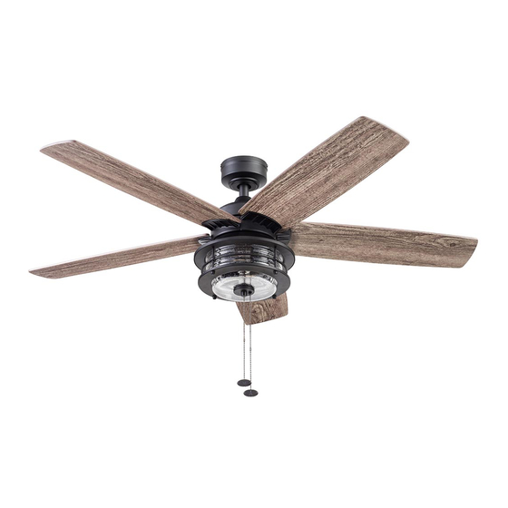
- Page 1 Home Foxhaven Ceiling Fan User Guide Model #51631, 51632...
-
Page 2: Package Contents
PACKAGE CONTENTS Canopy Canopy Cover Mounting Bracket Screw (x 4) Mounting Bracket Downrod Downrod Pin Downrod Clip Yoke Cover Set Screw (x 2) Motor Screw (x 10) Motor Assembly Fitter Plate Blade (x 5) Blade Arm (x 5) Fitter Plate Screw (x 3) Light Pan Light Pan Screw Light Kit... -
Page 3: Safety Information
SAFETY INFORMATION Please read and understand this entire manual before attempting to assemble, operate or install the product. • Before you begin installing the fan, disconnect the power by removing fuses or turning off the circuit breakers. • Make sure all electrical connections comply with local codes, ordinances, the National Electrical Code and ANSI/NFPA 70-199. -
Page 4: Care And Maintenance
SAFETY INFORMATION CAUTION: This device complies with Industry Canada license-exempt RSS standard(s). Operation is subject to the following two conditions: (1) this device may not cause interference, and (2) this device must accept any interference, including interference that may cause undesired operation of the device (if applicable). CAN ICES-005 (B) / NMB-005 (B) This device complies with Part 15 of the FCC Rules. -
Page 5: Initial Installation
PREPARATION Before beginning the assembly of this product, ensure all parts are present. Compare all parts with the package contents list and hardware contents list. If any part is missing or damaged, do not attempt to assemble the product. Estimated assembly time: 2 hours. Tools required (not included): Phillips Screwdriver, Safety Glasses, Step Ladder, Wire Cutters and Wire Strippers. - Page 6 STANDARD OR ANGLE MOUNT INSTRUCTIONS 1. Remove the downrod clip and downrod pin from the downrod. Then partially loosen the two set screws in the yoke at the top of the motor assembly (Figure 3.1). 2. Insert the downrod through the canopy and yoke cover. Feed the wires and braided cable from the fan through the downrod. (Figure 3.2).
-
Page 7: Final Installation
SECONDARY HANGING SYSTEM INSTRUCTIONS For installation in the United States: Building codes in the U.S.A. do not require installation of a Secondary Hanging System. If desired, the braided cable can be cut and removed using wire cutters (sold separately). Skip to FINAL INSTALLATION. For installation in Canada: In compliance with building codes in Canada, installation of the Secondary Hanging System is required. - Page 8 FINAL INSTALLATION 4. Insert the blade screws along with the blade washers through the blade and into the blade arm. Tighten each blade screw with a Phillips screwdriver (not included), starting with the one in the middle. Repeat this step for the remaining blades and blade arms (Figura 5.4).
- Page 9 FINAL INSTALLATION 10. Feed the pull chain coming from the off-center hole in the light kit through the grommet on the lower part of the light kit. Feed pull chains coming from the light kit through the center hole in the light cage. Then lift the light cage into the light pan and turn in a clockwise direction until the light cage is secure (Figure 5.10).
- Page 10 OPERATING INSTRUCTIONS The fan pull chain has four positions to control fan speed. One pull is HIGH, two is MEDIUM, three is LOW and four turns the fan OFF. The light pull chain has two positions -- OFF and ON (Figure 6.1). 2.
-
Page 11: Troubleshooting
TROUBLESHOOTING If you experience any faults, please check the Troubleshooting section below. If a problem cannot be remedied or you are experiencing difficulty in installation, please contact Customer Service: 1-877-361-3883. WARNING: Shut off the power supply before you begin any maintenance task. PROBLEM CORRECTIVE ACTION 1. -
Page 12: Limited Lifetime Warranty
Some states do not allow the disclaimer of implied warranties, so this disclaimer may not apply to you. REPLACEMENT PARTS LIST For replacement parts, call our customer service department 1-877-361-3883. Monday-Friday, 8am - 5pm, Central Time. The Honeywell Trademark is used under license from Honeywell International Inc ™. 51631 51632 Honeywell International Inc.
Need help?
Do you have a question about the Foxhaven 51631 and is the answer not in the manual?
Questions and answers
How do you remove the cover to replace the lightbulbs?