HME Clear-Com FreeSpeak Edge Base Station User Manual
Hide thumbs
Also See for Clear-Com FreeSpeak Edge Base Station:
- User manual (140 pages) ,
- Quick start manual (2 pages)

Related Manuals for HME Clear-Com FreeSpeak Edge Base Station


Summary of Contents for HME Clear-Com FreeSpeak Edge Base Station
- Page 1 User Guide FreeSpeak Edge Base Station User Guide Part Number: PUB-00113 Revision D May 02, 2024...
- Page 2 The product described in this document is distributed under licenses restricting its use, copying, distribution, and decompilation / reverse engineering. No part of this document may be reproduced in any form by any means without prior written authorization of Clear-Com, an HME Company.
-
Page 3: Table Of Contents
Table of contents Table of contents 1 Introduction 1.1 Product Features 1.2 FreeSpeak Edge Base Station Interconnections 2 Installing FreeSpeak Edge Base Station 2.1 Front Panel Connectors, Controls and Indicators 2.2 Intercom Touchscreens 2.3 Rear Panel Connectors and Indicators 2.4 System Powering 2.5 Clear-Com Ethernet Cable Recommendations 2.6 Stage Announce and Program Feed 2.7 Setting the Management IP Address... - Page 4 6 Using FreeSpeak Wireless Intercom 6.1 Overview of Transceivers 6.2 Connecting Transceivers Over E1 6.3 Adding IP Transceivers 6.4 Connecting Transceivers Over IP 6.5 Network Setup for IP Transceivers 6.6 Registering FreeSpeak Beltpacks 6.7 FS Edge Transceivers 7 Using Dante Systems 8 Using 2-Wire Systems 8.1 Introduction to 2-Wire Systems 8.2 2-Wire Port Compatibility...
- Page 5 11.10 Monitoring the Event Log 11.11 Monitoring the Logic Page (Status) 12 Security 12.1 Warning 12.2 Introduction 12.3 Forcing HTTPS 12.4 Using Security Certificates 13 Upgrading Firmware 13.1 Upgrading using the CCM 13.2 Upgrading using a USB stick 14 Spare parts 15 Front Panel Menu Reference Tables 15.1 Audio Settings 15.2 Host Settings...
- Page 6 19.2 Host Settings 19.3 2 W Audio (A/B) (C/D) 19.4 Discovery 19.5 Transceiver 19.6 Networking 19.7 Administration 20 Regulatory Compliance (Regulatory Model: 1410) 20.1 FCC Notice 20.2 FCC/IC/EC RF Exposure Warning 20.3 Industry Canada Compliance Statement 20.4 Korean Notice 20.5 European Union (CE mark) 20.6 United Kingdom (UKCA Mark) 20.7 Electrical and Electronic Equipment (WEEE) Waste Page 6...
-
Page 7: Introduction
User Guide | FreeSpeak Edge Base Station Introduction This chapter provides an overview of the FreeSpeak Edge Base Station. It contains the following sections: 1.1 Product Features 1.2 FreeSpeak Edge Base Station Interconnections Page 7... -
Page 8: Product Features
User Guide | FreeSpeak Edge Base Station Product Features FreeSpeak Edge Base Station is a low-latency intercom platform that interconnects with wired and wireless intercom systems. It supports: Six IP transceivers (any combination up to a total of six of FreeSpeak II and FreeSpeak Edge TCVRs) 10 E1 transceivers (any combination up to a total of 10 of FreeSpeak II 1.9 and 2.4 TCVRs) -
Page 9: Freespeak Edge Base Station Interconnections
User Guide | FreeSpeak Edge Base Station FreeSpeak Edge Base Station Interconnections The following graphic shows an overview of how the FreeSpeak Edge Base Station can interconnect with other intercom components. Page 9... -
Page 10: Installing Freespeak Edge Base Station
User Guide | FreeSpeak Edge Base Station Installing FreeSpeak Edge Base Station This chapter describes the front and rear panels, power supplies and cabling recommendations. It also describes network setup and illustrates example applications. It contains the following sections: 2.1 Front Panel Connectors, Controls and Indicators 2.2 Intercom Touchscreens 2.3 Rear Panel Connectors and Indicators 2.4 System Powering... -
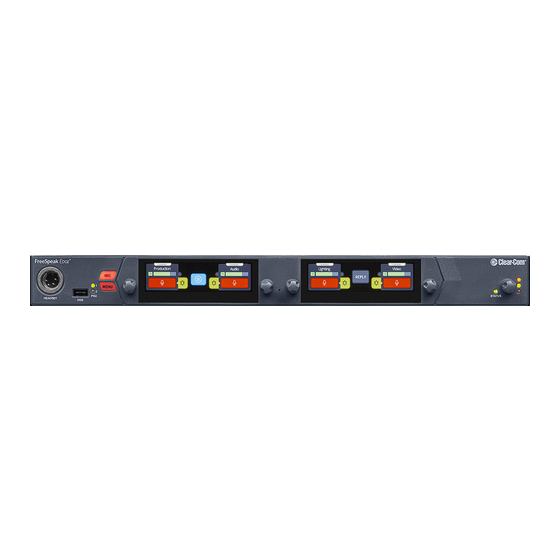
Page 11: Front Panel Connectors, Controls And Indicators
User Guide | FreeSpeak Edge Base Station Front Panel Connectors, Controls and Indicators The FreeSpeak Edge front panel connectors, controls and indicators are listed below. Item Description Headset connector (4-pin XLR female) Microphone key Menu key Rotary Encoders. Use these to control channel volume, mute or unmute audio, or to navigate through the menu system. -
Page 12: Intercom Touchscreens
User Guide | FreeSpeak Edge Base Station Item Description Power Input LEDs USB A connector. Use to: Register beltpacks Upgrade the Base Station Save/Restore system settings Obtain detailed logs for diagnostic purposes Intercom Touchscreens The Base Station has two intercom control touchscreens, available when the front panel screens are not in menu mode. - Page 13 User Guide | FreeSpeak Edge Base Station Item Description Listen activation indicator. Volume level indicator. Control the volume with the rotary controller next to the channel/audio source. Talk button. Call button. Use this to send a call signal. Menu button. Touch to see: Stage Announce All talk Remote mic kill (RMK)
- Page 14 User Guide | FreeSpeak Edge Base Station Item Description Channel indication. Audio routes can be point-to-point or channels. Notification bar Beltpack registration Progress of upgrades Support information gathering Resoration of configuration progress Reply button. Use CLEAR to clear the currently visible entry (does not clear the entire key stack).
-
Page 15: Rear Panel Connectors And Indicators
User Guide | FreeSpeak Edge Base Station Rear Panel Connectors and Indicators The rear connectors and indicators are listed below. Item Description Internal power connector. Mains power lead with internal power supply. Grounding screw. General Purpose Input/Output connectors x2 (DB-9F). GPIO 1 contains GPI1 and GPO1 &... -
Page 16: System Powering
User Guide | FreeSpeak Edge Base Station Item Description SA/PGM. RJ45 for SA and RJ45 to XLR for PGM. External power supply connector (12V DC). CAUTION: Before using, see System Powering on page System Powering FSEBase Station features dual power inputs: Mains power connector (IEC) internal power supply DC connector. - Page 17 User Guide | FreeSpeak Edge Base Station 1. Connect the external power supply 12V cable connector (A) to the rear chassis 12V input connector of the Station. Note: When connecting the power cable, be sure to push until the connector locks into the device. 2.
-
Page 18: Clear-Com Ethernet Cable Recommendations
User Guide | FreeSpeak Edge Base Station Clear-Com Ethernet Cable Recommendations Cable recommendations Category (Cat) Higher Cat numbers will support a higher bandwidth. Therefore, by using a higher Cat number you are future proofing your system to some extent. Example: Cat 5e : up to 1 GB Cat 6: up to 10 GB Use Cat 5e or higher. ... -
Page 19: Setting The Management Ip Address
User Guide | FreeSpeak Edge Base Station Program audio (PGM), you must connect this to the RJ45 port labeled SA/PGM (port 8) on the rear of your device, and connect your input (PGM) and output (SA) to these connectors. Stage announce (audio out): Male XLR Program feed (audio in): Female XLR Navigate to Configuration >... -
Page 20: Saving And Restoring System Configuration
User Guide | FreeSpeak Edge Base Station Saving and Restoring System Configuration Clear-Com recommends that you make a backup of your system configuration using the Save option that is available in the CCM and the front panel menu system. 2.8.1 Saving System Configuration in the CCM The Save and Restore options are available in the CCM top navigation bar. -
Page 21: Resetting To Default
User Guide | FreeSpeak Edge Base Station Resetting to Default Your Base Station can be reset to default settings either from the front panel menus or from the Core Configuration Manager (CCM). Note: When you use a pin reset on front the front of the Base Station the device reboots. 2.9.1 Resetting to Default from the Base Station Menu System 1. -
Page 22: Configuring From The Front Panel
User Guide | FreeSpeak Edge Base Station Configuring from the Front Panel This chapter describes how to configure the FreeSpeak Edge Base Station from the front panel. It contains the following sections: 3.1 Introduction to Configuring from the Front Panel 3.2 Setting the Management IP Address 3.3 Passwords, Addresses, Reset to Default, Save and Restore Configuration 3.4 Front Panel Menus... -
Page 23: Introduction To Configuring From The Front Panel
User Guide | FreeSpeak Edge Base Station Introduction to Configuring from the Front Panel Some common tasks you might perform from the front panel menus are: See/configure the Base Station IP address See the default CCM password Null your 2-wire audio ports Reset the Base Station to factory settings Reset the CCM password To enter the Base Station menu system, press the Menu button on the front panel. -
Page 24: Passwords, Addresses, Reset To Default, Save And Restore Configuration
User Guide | FreeSpeak Edge Base Station 3.2.1 Setting the Management IP Address from the Front Panel Menus 1. Press the MENU button. 2. Using the far left rotary controller, navigate to Networking. 3. Select Management. 4. Navigate to DHCP and select DISABLED. Push to select menu item. 5. - Page 25 User Guide | FreeSpeak Edge Base Station 3.3.2 Find the default password for the CCM 1. Press the Menu button on the front of the Base Station. 2. Navigate to Administration > CCM Access > Default Password using the rotary controllers.
- Page 26 User Guide | FreeSpeak Edge Base Station 3.3.4 Reset the CCM password 1. Press the Menu button on the front of the Base Station. 2. Using the right hand rotary controller select Administration > Reset > Reset CCM Pass. 3. Press the right hand rotary controller. 4.
-
Page 27: Front Panel Menus
User Guide | FreeSpeak Edge Base Station Front Panel Menus The front panel menu option are listed below. 3.4.1 Audio Settings Headset Headset Limit. This allows the user to set the headset limiter for the front panel headset. -12 dB to +8 dB/ OFF HS Mic Type Dynamic (default) Electret... - Page 28 User Guide | FreeSpeak Edge Base Station 3.4.3 2W Audio (A,B) Configure power settings for 2-wire audio sources and perform nulling. Interface - power settings Power detected? Yes/No Power Enabled/Disabled (default = disabled) Mode Clear-Com/RTS (default = Clear-Com) Nulling: 2W A and 2W B.Press the rotary control (Start) to perform a null. Nulling is only available if power is detected.
- Page 29 User Guide | FreeSpeak Edge Base Station 3.4.7 Networking Management Configure and view: LAN Port Assignment DHCP Enabled/Disabled IP Address (read only when DHCP is Enabled) Subnet Mask (read only when DHCP is Enabled) MAC Address (read only) Push the fourth rotary to open the on screen toucnscreen keyboard to change IP and Subnet. [OK] when done.
- Page 30 User Guide | FreeSpeak Edge Base Station 3.4.8 Administration Beltpacks Over the Air: Press rotary four to Start OTA. Put the Base Station in pairing mode for OTA registration of beltpacks (600 seconds). BP Role List Sorting: Role Number Alphabetical Battery type: use this setting if the beltpacks are not using the supplied Li-ion batteries.
- Page 31 User Guide | FreeSpeak Edge Base Station Settings Save Restore CCM Access Username Default password Hardware (view only) Information is for troubleshooting purposes only. Please note: the serial number in this section is the electronic main board serial number, not the device serial number. Page 31...
-
Page 32: The Core Configuration Manager (Ccm)
User Guide | FreeSpeak Edge Base Station The Core Configuration Manager (CCM) This chapter describes the main pages of the Core Congfiguration Manager (CCM). It contains the following sections: 4.1 Changing the CCM Password 4.2 Hardware Page Overview 4.3 Configuration Page Overview 4.4 Status Page Page 32... -
Page 33: Changing The Ccm Password
User Guide | FreeSpeak Edge Base Station Changing the CCM Password Change the password to one of your own choosing in the top right corner of the navigation bar. Note: You can reset your password to the default at any time from the Base Station front panel menus. Hardware Page Overview The Hardware page of the CCM is where you set up your system. - Page 34 User Guide | FreeSpeak Edge Base Station The Resources Page Click the Resources tab to see the resources page. This gives an overview of the hardware and ports that are present. From this page, you can use the Add Resource button to: View a list of both discovered and registered IP transceivers Add any discovered IP transceivers to the system Remove any registered IP transceivers from the system...
-
Page 35: Configuration
User Guide | FreeSpeak Edge Base Station Configuration Page Overview The Configuration page of the CCM is where you configure the intercom routing aspects of your system (add audio to channels and set up talk and call keys for beltpacks). It consists of four areas: Channels Roles... - Page 36 User Guide | FreeSpeak Edge Base Station 4.3.1 Channels Page The Channels page enables you to view channels and add ports to channels. Audio keys are added to channels in the Roles page. The center panel on this screen shows the live state of audio routing.
- Page 37 User Guide | FreeSpeak Edge Base Station 4.3.3 Roles Page The Roles page enables you to create roles for the devices in your intercom system. Roles are made for: The Base Station FreeSpeak II beltpacks FreeSpeak Edge beltpacks A role can be made that can be used with either an FS II beltpack or an FS Edge beltpack (this role can only be used on one beltpack at any one time).
- Page 38 User Guide | FreeSpeak Edge Base Station 4.3.4 Logic Page The Base Station offers six fully configurable GPIOs, increasing the range and possible uses of controls and relays. 2 x GPIs. These can be used, for example, to allow the station operator to open an audio route to a Channel using a foot switch, or to route a program feed to a Channel, Group or beltpack when an on-air light comes on.
-
Page 39: Status Page
User Guide | FreeSpeak Edge Base Station Status Page From the Status page of the CCM, you can view the status of all the resources that are connected to the FreeSpeak Edge Base Station. These include: Transceivers (IP and E1) Beltpacks Interface ports Here you will see error and warning states. -
Page 40: Example Applications
User Guide | FreeSpeak Edge Base Station Example Applications This chapter contains examples of typical applications. It contains the following sections: 5.1 FreeSpeak Edge Base with Freespeak II Wireless - E1 5.2 FreeSpeak Edge Base with FreeSpeak II Wireless-E1 and Splitter 5.3 FreeSpeak Edge Base with FreeSpeak Edge IP Transceivers 5.4 Split Frequency Setup (5, 2.4 and 1.9 GHz System) Page 40... -
Page 41: Freespeak Edge Base With Freespeak Ii Wireless - E1
User Guide | FreeSpeak Edge Base Station FreeSpeak Edge Base with Freespeak II Wireless - E1 The FreeSpeak II E1 transceivers use an E1 connection (telecommunications standard) directly to the Base Station. The Core Configuration Manager (CCM) is the easiest way to configure your system, but this setup can be configured with minimal use of the CCM if you work with the default role setup. - Page 42 User Guide | FreeSpeak Edge Base Station 5.1.1 Outline of General Setup and Configuration For E1 setup, see Connecting Transceivers Over E1 on page To access the CCM, see: The Core Configuration Manager (CCM) on page To register beltpacks, see Registering FreeSpeak Beltpacks on page To set Port Function, see Setting Port Function (Pinout) on a 4-Wire Connection on...
-
Page 43: Freespeak Edge Base With Freespeak Ii Wireless-E1 And Splitter
User Guide | FreeSpeak Edge Base Station FreeSpeak Edge Base with FreeSpeak II Wireless-E1 and Splitter This setup includes two splitters, both connected via shielded Cat 5e cable using E1 connectivity. Four channels are configured in the CCM: Channel 1=ALL, Channel 2=Lighting, Channel 3=Sound, Channel 4=FoH. - Page 44 User Guide | FreeSpeak Edge Base Station 5.2.1 Outline of General Setup and Configuration For E1 setup, see Connecting Transceivers Over E1 on page To set the splitter DIP switches, see the FSII Splitter Quick Start Guide (FSII SPL-QSG) in the Clear-Com FreeSpeak II Knowledge Center on the Clear-Com website: Clear-Com Freespeak II Knowledge Center To access the CCM, see...
-
Page 45: Freespeak Edge Base With Freespeak Edge Ip Transceivers
User Guide | FreeSpeak Edge Base Station FreeSpeak Edge Base with FreeSpeak Edge IP Transceivers This setup has a total of 6 FS Edge transceivers with 16 beltpacks. The transceivers are connected via a network that is configured for AES67 traffic. These are configured using the CCM. - Page 46 User Guide | FreeSpeak Edge Base Station 5.3.1 Outline of General Setup and Configuration For network setup, see Network Setup for IP Transceivers on page To access the CCM, seeThe Core Configuration Manager (CCM) on page To add IP transceivers to your system, see Using FreeSpeak Wireless Intercom on page For information on the connection process for IP transceivers, see the Quick Start Guides...
-
Page 47: Split Frequency Setup (5, 2.4 And 1.9 Ghz System)
User Guide | FreeSpeak Edge Base Station Split Frequency Setup (5, 2.4 and 1.9 GHz System) This setup has: E1 FS II transceivers (1.9) with 5 beltpacks E1 FS II transceivers (2.4) with 4 beltpacks FS Edge IP transceivers (5) with 10 beltpacks FS II IP transceivers (1.9) with 10 beltpacks. -
Page 48: Using Freespeak Wireless Intercom
User Guide | FreeSpeak Edge Base Station Using FreeSpeak Wireless Intercom This chapter describes how to connect to E1 and IP transceivers. It contains the following sections: 6.1 Overview of Transceivers 6.2 Connecting Transceivers Over E1 6.3 Adding IP Transceivers 6.4 Connecting Transceivers Over IP 6.5 Network Setup for IP Transceivers 6.6 Registering FreeSpeak Beltpacks... -
Page 49: Overview Of Transceivers
User Guide | FreeSpeak Edge Base Station Overview of Transceivers Connecting Transceivers Over E1 E1 is a telecommunications standard whereby data and power are sent over Cat 5/6 or Fiber cable. E1 connections must have dedicated cabling as it is not possible to use network switches with this technology. - Page 50 User Guide | FreeSpeak Edge Base Station Example connection with a splitter Note: The splitter connections are switched between RJ45 and Fiber routing using DIP switches inside the splitter. For more examples of connection options and how to set the DIP switches, see the FreeSpeak II Splitter Quick Start Guide available from the FreeSpeak II Knowledge Center.
- Page 51 User Guide | FreeSpeak Edge Base Station Splitter to TCVRs 328 ft (100 m) using shielded 24 AWG Cat 5/6e cable TCVRs powered by splitter 164 ft (50 m) using shielded 26 AWG Cat 5/6e cable 2625 ft (800 m) using shielded 24 AWG Cat 5/6e cable TCVRs have local/direct power 1312 ft (400 m) using shielded 26 AWG...
- Page 52 User Guide | FreeSpeak Edge Base Station 6.2.3 E1 Transceiver/Splitter Port Connection Type (RJ45 or Fiber) Transceivers/splitters can be connected to the Base Station using either RJ45 cable or fiber cable. You can have two RJ45 connections, two Fiber connections or one RJ45 and one Fiber. The connection type for the ports is determined by a software setting in the Core Configuration Manager (CCM).
- Page 53 User Guide | FreeSpeak Edge Base Station 6.2.5 Setting Cable Length Offset (E1) Cable length offset is used to optionally align the DECT or radio signals between transceivers. If transceivers are not synchronized, beltpack handover will not happen effectively. This is particularly important if you have overlapping transceiver coverage zones (RF cells) or the beltpacks need to move between coverage zones.
-
Page 54: Adding Ip Transceivers
User Guide | FreeSpeak Edge Base Station Adding IP Transceivers Note: To add E1 transceivers, see Connecting Transceivers Over E1 on page To add IP transceivers: 1. Navigate to Hardware > Resources and select Add Resource. The following screen appears. 2. -
Page 55: Connecting Transceivers Over Ip
User Guide | FreeSpeak Edge Base Station Connecting Transceivers Over IP When connecting IP transceivers, connect them to the LAN connector that is configured for AES67 on the rear of the Base Station using Ethernet cable. Network Setup for IP Transceivers on page Once your transceivers are set up on the network you will add them to your system using the CCM. -
Page 56: Network Setup For Ip Transceivers
User Guide | FreeSpeak Edge Base Station Network Setup for IP Transceivers The FreeSpeak Edge Base Station has LAN connections assignable to different network traffic such as Managment, AES67, Dante and so on. The LAN ports are fully user configurable but you can work with the following default settings: LAN 1: Management LAN 2: AES67 for FreeSpeak IP Transceivers LAN 3: Not configured (SFP) - Page 57 User Guide | FreeSpeak Edge Base Station 6.5.2 Connection to IP Transceivers and Dante, Example 2 Page 57...
- Page 58 User Guide | FreeSpeak Edge Base Station 6.5.3 Connection to IP Transceivers and Dante, Example 3 Page 58...
- Page 59 User Guide | FreeSpeak Edge Base Station 6.5.4 Connection to IP Transceivers, Example 4 If you are connecting to a network set up with heavy traffic, Clear-Com recommends that you split AES67 traffic into its own segment. Page 59...
-
Page 60: Registering Freespeak Beltpacks
User Guide | FreeSpeak Edge Base Station 6.5.5 Setup Rules The default setup, Management on LAN 1 and AES67 on LAN 2, allows your computer to be connected directly to the FreeSpeak Edge Base Station for configuration and a dedicated switch to LAN 2 for FreeSpeak IP transceivers. This is in order to accommodate the IP transceivers' need for high clocking accuracy. - Page 61 User Guide | FreeSpeak Edge Base Station 6.6.1 Registering a beltpack by USB cable This method of registering beltpacks is recommended for fast and easy set up. To register a beltpack using a USB cable, connect a beltpack to Base Station using a USB A to micro USB B (FSII) / USB C (FSE) cable.
- Page 62 User Guide | FreeSpeak Edge Base Station 6.6.3 Unregistering a beltpack To unregister a beltpack, navigate to Hardware > Resources > Endpoints (click the down arrow to see all connected Endpoints (beltpacks). Select an Endpoint by clicking on it. Select Unregister.
-
Page 63: Fs Edge Transceivers
User Guide | FreeSpeak Edge Base Station FS Edge Transceivers Wireless region and channel setup are important when using FS Edge transceivers. 6.7.1 Wireless Region Your Edge transceiver has a wireless region pre-configured, in order to comply with regional regulations. The wireless region setting in the CCM MUST match that of your transceiver, or the system will not work. - Page 64 User Guide | FreeSpeak Edge Base Station 6.7.2 Channel Scanning The FreeSpeak Edge transceiver system will automatically select channel 1, 2 and a backup channel (if using DFS channels) on each transceiver when you set it up. For best performance, it is necessary to ensure that selected channels are clear of interference from other devices.
- Page 65 User Guide | FreeSpeak Edge Base Station 6.7.3 Channel Score Channel Score is calculated using a weighted combination of: • RSSI (Received Signal Strength Indicator) • Channel activity (Use) • Access points (Ap) To scan all the transceivers in your network simultaneously, go to Hardware > Host > Wireless >...
-
Page 66: Using Dante Systems
User Guide | FreeSpeak Edge Base Station Using Dante Systems To configure Dante you must be familiar with the Audinate Dante Controller, available from the Audinate website. Before configuring the connection in the Dante Controller, you must determine which of the 4 LAN connectors on the Base Station you wish to use for Dante network traffic. - Page 67 User Guide | FreeSpeak Edge Base Station LAN connectors can be configured in any way you wish, but the CCM enforces that you can not configure IP transceivers (AES67) and Dante traffic on the same network. This is because AES67 network traffic has defferent timing requirements than Dante network traffic for FreeSpeak IP transceivers.
- Page 68 User Guide | FreeSpeak Edge Base Station 5. Details can also be viewed in the Dante Controller. 6. In the CCM navigate to Hardware>Resources>Dante Ports and add Dante ports. Give the new ports a suitable label. 7. Route the channels as required in the Dante Controller. Page 68...
- Page 69 User Guide | FreeSpeak Edge Base Station 8. You will see available Dante ports in the Configuration page of the CCM. These ports can be assigned to channels on the Base Station in the usual way. 9. Select the required channel click the + icon next to the port. Page 69...
-
Page 70: Using 2-Wire Systems
User Guide | FreeSpeak Edge Base Station Using 2-Wire Systems This chapter describes how to use the FreeSpeak Edge Base Station with 2-Wire intercom devices. It contains the following sections: 8.1 Introduction to 2-Wire Systems 8.2 2-Wire Port Compatibility Page 70... -
Page 71: Introduction To 2-Wire Systems
User Guide | FreeSpeak Edge Base Station Introduction to 2-Wire Systems When connecting 2-wire equipment the following applies: Terminate 2-wire partyline circuits must be terminated once on the line Do not terminate on more than one device in the system Enable/disable the termination. - Page 72 User Guide | FreeSpeak Edge Base Station Enable/disable the partyline power. Default setting: Disabled The Station default setting assumes the 2-wire partyline is powered elsewhere in the system (i.e. using a partyline main station or power supply) These functions can be set either in the 2-wire port settings page of the CCM or from the front panel menu on the Station Null 2-wire null serves the purpose of isolating audio that goes to the 2-wire partyline...
- Page 73 User Guide | FreeSpeak Edge Base Station To configure 2-wire port settings in the CCM navigate to: Hardware > Resources > Physical Ports > (select port) : Page 73...
-
Page 74: 2-Wire Port Compatibility
User Guide | FreeSpeak Edge Base Station 2-Wire Port Compatibility When connecting Clear-Com Stations to other Clear-Com equipment and third-party systems (2-wire) use the following guidelines. Device Type Supports call signalling? HelixNet HLI-2W2* Yes Encore MS-702/4 Yes Encore RS Beltpack RS-701 / 702 / 703 Yes Yes, but does not pass call signalling to 4-wire RTS 2-wire equipment... -
Page 75: Using 4-Wire Systems
User Guide | FreeSpeak Edge Base Station Using 4-Wire Systems This chapter describes how to use the FreeSpeak Edge Base Station with 4-Wire intercom devices. It contains the following sections: 9.1 Connecting 4-Wire 9.2 Port Function (4-Wire Pinout) 9.3 Connecting 4-Wire Clear-Com to Clear-Com 9.4 Setting Port Function (Pinout) on a 4-Wire Connection Page 75... -
Page 76: Connecting 4-Wire
User Guide | FreeSpeak Edge Base Station Connecting 4-Wire When referring to intercoms, a four-wire circuit describes an intercom connection (I/O) where there are four wires (two paths) and the paths are different for talk and listen. Analog or four-wire circuits use two pairs for balanced line-level audio signals, one for input and the other for output, using four wires in total. - Page 77 User Guide | FreeSpeak Edge Base Station Audio Out + Audio In + Audio In - Audio Out - Note: Always read your 3rd party device manual before connecting to Clear-Com. Note: The above diagram illustrates the default pinout mode for Clear-Com RJ45 : 4-wire-X. See Port Function for details.
- Page 78 User Guide | FreeSpeak Edge Base Station XLR Breakout Cable Termination to RJ45 4-Wire A breakout cable is supplied with the Arcadia and Edge stations. For other connections you need to make your own cable. CAB-RJ45-PGM-SA - Four-Wire Analog Audio Splitter Cable - PGM/SA with RJ45 to 3-pin XLR-F &...
- Page 79 User Guide | FreeSpeak Edge Base Station XLR Panel Termination to RJ45 4-Wire Page 79...
-
Page 80: Port Function (4-Wire Pinout)
User Guide | FreeSpeak Edge Base Station Port Function (4-Wire Pinout) Some 4-wire RJ45 connectors on Clear-Com products include a software configuration that switches audio I/O pin configuration according to the device you are connecting to. This means that when connecting to Clear-Com devices, a cross-over cable is not necessary. Clear-Com devices can have the following RJ45 4-wire pinouts: Clear-Com 4-Wire (To Panel on older systems) Clear-Com 4-Wire -X(To Matrix on older systems) -
Page 81: Connecting 4-Wire Clear-Com To Clear-Com
Clear-Com RJ45 pinout type on this device Device (Port Function) FreeSpeak II 4-wire-X (fixed) HelixNet HLI-4W2 4-wire-X (fixed) HME DX200/DX210/DX410 4-wire-X (fixed) Eclipse MVX-A16 4-wire (fixed) FreeSpeak II Base II Configurable. Default setting is 4-wire-X FreeSpeak Edge BaseArcadia Central Configurable. Default setting is 4-wire-X. -
Page 82: Setting Port Function (Pinout) On A 4-Wire Connection
User Guide | FreeSpeak Edge Base Station Setting Port Function (Pinout) on a 4-Wire Connection 1. Connect the devices using 1:1 Cat5/6/6e cable. 2. In the CCM, navigate to Hardware > Resources > Physical Ports. 3. Select the 4-wire port. 4. -
Page 83: Network Setup
User Guide | FreeSpeak Edge Base Station Network Setup This chapter describes how to set up and configure your network for FreeSpeak Edge Base Station IP transceivers. It contains the following sections: 10.1 Network Setup for IP Transceivers 10.2 LAN Configuration Rules 10.3 AES67 Network - PTP Follower Configuration Page 83... -
Page 84: Network Setup For Ip Transceivers
User Guide | FreeSpeak Edge Base Station 10.1 Network Setup for IP Transceivers The FreeSpeak Edge Base Station has LAN connections assignable to different network traffic such as Managment, AES67, Dante and so on. The LAN ports are fully user configurable but you can work with the following default settings: LAN 1: Management LAN 2 LAN 3: Not configured (SFP) - Page 85 User Guide | FreeSpeak Edge Base Station 10.1.2 Connection to IP Transceivers and Dante, Example 2 Page 85...
- Page 86 User Guide | FreeSpeak Edge Base Station 10.1.3 Connection to IP Transceivers and Dante, Example 3 Page 86...
- Page 87 User Guide | FreeSpeak Edge Base Station 10.1.4 Connection to IP Transceivers, Example 4 If you are connecting to a network set up where there is lots of traffic, either management or AES67, Clear-Com recommends that you split AES67 traffic into its own segment. Page 87...
-
Page 88: Lan Configuration Rules
User Guide | FreeSpeak Edge Base Station 10.1.5 Setup Rules The default setup, Management on LAN 1 and AES67 on LAN 2, allows your computer to be connected directly to the Base Station for configuration and a dedicated switch to LAN 2 for FreeSpeak IP transceivers. - Page 89 User Guide | FreeSpeak Edge Base Station 10.2.2 IP Rules The IP addresses cannot be in the reserved range: 10.0.0.0-10.0.0.7 The subnet mask may cause an overlap with the reserved range The IP addresses cannot be in the LQ tunnel range 172.23.xxx.xxx The IP addresses cannot be in the localhost range 127.xxx.xxx.xxx The IP addresses cannot be in the multicast range 224.xxx.xxx.xxx-239.xxx.xxx.xxx 10.2.3...
-
Page 90: Aes67 Network - Ptp Follower Configuration
User Guide | FreeSpeak Edge Base Station 10.3 AES67 Network - PTP Follower Configuration Arcadia and Edge v. 3.0 and upwards By default, the intercom stations (Arcadia and Edge) have clocking status: Reference (IEEE 1588 Master). Change the status of the intercom station clocking function to Follower (IEEE 1588 Slave) by enabling PTP Follower Mode. - Page 91 User Guide | FreeSpeak Edge Base Station In the CCM navigate to : Status > Overview > Host Device > Stats: For information and history, also look in the event log: Status > Event Log. Page 91...
-
Page 92: Configuring From The Ccm
User Guide | FreeSpeak Edge Base Station Configuring from the CCM This chapter describes how to use the CCM to set up, configure and monitor your intercom system. It contains the following sections: 11.1 Configuring Station Settings 11.2 Adding IP Transceivers 11.3 Registering Beltpacks 11.4 Channels and Groups 11.5 Managing Channels... -
Page 93: Configuring Station Settings
User Guide | FreeSpeak Edge Base Station 11.1 Configuring Station Settings To configure the Base Station, navigate to Hardware>Hosts. Here you can: Configure the network Upgrade the Base Station and connected resources Change the following wireless beltpack system settings: Beltpack administration pin numbers FS Edge wireless region (important for system compliance) FSII battery type, if you are not using the supplied Li-ion batteries you may use Alkaline or NiMH type batteries... - Page 94 User Guide | FreeSpeak Edge Base Station 11.1.1 Configuring the Network After changing the network configuration, you must click Apply or [Enter] key. For information see LAN Configuration Rules on page Page 94...
- Page 95 User Guide | FreeSpeak Edge Base Station 11.1.2 Upgrading To upgrade the Base Station and connected resources: 1. Select the Upgrade tab. 2. Select File then navigate to where the upgrade file is stored on your computer. 3. Select the file and when the Upgrade button lights, click it. This begins the upgrade process.
- Page 96 User Guide | FreeSpeak Edge Base Station 11.1.3 Setting Up the Wireless Beltpack System Select the Wireless tab. From the Wireless tab, you can set or view the following System and Station settings. System The administration pin for your wireless system, used by the beltpack to be able to access privileged functionality System ID.
- Page 97 User Guide | FreeSpeak Edge Base Station Select from a list of 5 GHz channels that you can exclude and prevent transceivers from using Scan all transceivers. Use this feature to scan the local 5 GHz RF space. All available channels will be scanned, and traffic reported.
-
Page 98: Adding Ip Transceivers
User Guide | FreeSpeak Edge Base Station FreeSpeak II Splitter/Transceiver ports: select RJ45 or Fiber connectivity for each port Audio RF Filter (improve resilience to corrupt wireless transmission) - for use with E1 1.9GHz transceivers only AA Battery type. You can choose not to use the Li-ion batteries supplied with the beltpacks, in which case you must specify battery type here. -
Page 99: Registering Beltpacks
User Guide | FreeSpeak Edge Base Station 3. Select the transceiver that you want to register from the left-hand area of the screen, and click the right-hand arrow. The selected transceiver appears in the right-hand list of registered transceivers. 11.3 Registering Beltpacks Before you can use a beltpack, you must register it. - Page 100 User Guide | FreeSpeak Edge Base Station 11.3.2 Registering a beltpack OTA To register a beltpack using OTA: 1. Navigate to Hardware > Resources and click Add Resource. The following screen appears: 2. Click Start OTA Registration. Note: A timer is started indicating how long the system is open for registration. You can close OTA registration on the system at any point.
-
Page 101: Channels And Groups
User Guide | FreeSpeak Edge Base Station 11.3.3 Unregistering a beltpack To unregister a beltpack, navigate to Hardware > Resources > Endpoints (click the down arrow to see all connected Endpoints. Select an Endpoint by clicking on it. Select Unregister. 11.4 Channels and Groups Channels and groups are both essentially digital containers for audio sources, allowing... - Page 102 User Guide | FreeSpeak Edge Base Station The default key behavior setting for a wireless beltpack in a Channel is Talk and Forced Listen. For more information, see Key Behavior. Page 102...
-
Page 103: Managing Channels
User Guide | FreeSpeak Edge Base Station 11.4.2 Groups A Group configuration enables an announcement or broadcast to a number of members at the same time. A group member can reply directly to the announcer using the Reply key. The other group members will not hear this. - Page 104 User Guide | FreeSpeak Edge Base Station 11.5.1 Viewing Information About a Channel When you open the Channels screen, the left-hand panel displays a list of all the channels that are currently present. The following information is displayed for each channel. Page 104...
- Page 105 User Guide | FreeSpeak Edge Base Station Status A green tick mark indicates that all the ports that are configured for the channel are connected. Otherwise, a warning triangle is shown. Name This field contains a label that enables you to identify the channel. Note: A label can contain up to 10 characters.
- Page 106 User Guide | FreeSpeak Edge Base Station Display Labels 11.5.3 Adding a New Channel To add a new channel: 1. Click the new channel icon . A new entry appears in the list of added channels. Note: You can only add new channels up to a maximum number (100). 2.
- Page 107 User Guide | FreeSpeak Edge Base Station 11.5.4 Adding Ports to a Channel To add ports to a channel: 1. From the Channel panel, select the channel in which the port is to be added. 2. From the Ports panel, click the add port icon of the port that you require.
-
Page 108: Managing Groups
User Guide | FreeSpeak Edge Base Station 11.5.5 Removing Ports From a Channel To remove a port from a channel: 1. From the Channels panel, select the required channel. 2. Click the remove icon of the port that you want to remove. The port is removed. - Page 109 User Guide | FreeSpeak Edge Base Station 11.6.1 Viewing Information About a Group When you open the Groups screen, the left-hand panel displays a list of all the groups that have been created. The following information is displayed for each group. Status A green tick mark indicates that all the ports that are configured for group are connected.
- Page 110 User Guide | FreeSpeak Edge Base Station Online This indicates how many of the total group members are online. Talkers This indicates how many FS II beltpacks or logic-routed ports have active talk routes on this group. 11.6.2 Adding a New Group To add a new group: 1.
- Page 111 User Guide | FreeSpeak Edge Base Station 11.6.3 Adding Ports and Roles to a Group To configure a group you must first put the members in the group. These can be ports and/or roles. When you have done this you will configure a talk key to the group (group administrator). Adding Ports to a Group 1.
- Page 112 User Guide | FreeSpeak Edge Base Station Adding Roles to a Group 1. In the Roles page, select the role you wish to add to the group. 2. On the left side of the screen, select Group Membership. Page 112...
- Page 113 User Guide | FreeSpeak Edge Base Station Configuring a Talk Key to the Group 1. In the Roles page, select the role you want to talk to the group. 2. Configure a talk key to the group (Talk Only) When you have configured members and a talk key to a group, you will see the group by selecting it in the Groups page.
-
Page 114: Managing Roles
User Guide | FreeSpeak Edge Base Station 11.6.5 Deleting a Group To delete a group: 1. From the Groups panel, select the group that you want to delete. 2. Remove all the ports from the group Note: If you do not remove the ports, you will be prompted to do so in step 3. 3. - Page 115 User Guide | FreeSpeak Edge Base Station 11.7.2 Role Templates When you add roles, a new role is always created from a template role. Template roles are editable. If you edit a template role, any new roles created from it have the edited settings. Select a role template to edit the settings.
- Page 116 User Guide | FreeSpeak Edge Base Station 11.7.3 Adding Roles To add roles: 1. Navigate to Configuration > Roles. 2. Click Add Roles. The following screen appears. 3. Enter a label for the role, the number of roles required and choose which endpoints will use this role (FS II, FS Edge or both).
- Page 117 User Guide | FreeSpeak Edge Base Station beside each role in the left-hand side of the screen. 4. Click Create. The new role appears in the list of roles in the left-hand side of the Roles screen. Page 117...
- Page 118 User Guide | FreeSpeak Edge Base Station 11.7.4 Editing Role Key Assignment 1. Navigate to Configuration > Roles and select required role on the left of the screen. 2. Click on the small white squares. The key assignment screen appears. 3.
- Page 119 User Guide | FreeSpeak Edge Base Station 11.7.6 Cloning Roles To clone roles: 1. Navigate to Configuration > Roles, and select the role that you wish to clone from the list of roles in the left-hand side of the screen. 2.
- Page 120 User Guide | FreeSpeak Edge Base Station The role is deleted and removed from the list of roles in the left-hand side of the screen. Page 120...
- Page 121 User Guide | FreeSpeak Edge Base Station 11.7.8 Setting Key Behavior Audio keys can be set to different Talk and Listen states. These key behavior states apply to the keys on the Base Station and beltpacks. Key behavior is configured in the Roles tab in the CCM.
-
Page 122: Setting Up Gpios And Logic Events
User Guide | FreeSpeak Edge Base Station 11.8 Setting up GPIOs and Logic Events 2 x GPIs 4 x GPOs Unlimited Logic Events Each GPI/GPO hosts up to 10 different events or actions. These actions can be turned off or on in the Status > Logic page of the CCM. 2 x DB 9F connectors on the rear of the Base Station For DB 9F pinouts, see Appendix A: Pinouts on page... - Page 123 User Guide | FreeSpeak Edge Base Station When someone talks to stage announce, an output relay (GPO) is sent to the external stage announce speaker. When someone talks to a channel labeled Radio, an output is sent to a 2-way radio. When a call signal (Call) comes into a channel, and output is sent to turn on an on-air light.
- Page 124 User Guide | FreeSpeak Edge Base Station 11.8.5 Configuring GPOs In this example you send an output trigger (for example to an external stage announce speaker) on GPO1 when a beltpackTalk is activated on the stage announce (SA) 4-wire port. 1.
-
Page 125: Monitoring System Status
User Guide | FreeSpeak Edge Base Station 11.9 Monitoring System Status You can monitor your system using the following features of the CCM: Overview Event Log Logic 11.9.1 Overview To see the Overview screen, navigate to Status > Overview. The following screen appears. The Overview screen consists to two sections. - Page 126 User Guide | FreeSpeak Edge Base Station 11.9.2 System Icons Each icon is color-coded to give an easily accessible view of the status of each entity. The following legend is used to indicate the status of each entity. 11.9.3 Monitoring Wireless Devices Navigate to Status >...
- Page 127 User Guide | FreeSpeak Edge Base Station Transceiver details Page 127...
- Page 128 User Guide | FreeSpeak Edge Base Station Monitoring Beltpack Details 11.9.4 Monitoring the Host Device Page 128...
-
Page 129: Monitoring The Event Log
User Guide | FreeSpeak Edge Base Station 11.10 Monitoring the Event Log The Event Log provides useful information about events that happen in the system. The Event Log can be filtered on: Time: default is 1 month prior to the current date and time Exceptions (warnings and errors): default is unchecked. -
Page 130: Monitoring The Logic Page (Status)
User Guide | FreeSpeak Edge Base Station 11.11 Monitoring the Logic Page (Status) This page shows the GPIs and GPOs (relay) that you have set up in the Configuration > Logic page. You can see if these are currently active in the system under the Status column. A green icon indicates a currently active input or relay. -
Page 131: Security
User Guide | FreeSpeak Edge Base Station Security 12.1 Warning The CCM ensures that you do not turn off port 80 without testing your certificate. If you turn off port 80 without ensuring that you can reach the CCM using port 433 it is possible to get locked out of your CCM. -
Page 132: Forcing Https
User Guide | FreeSpeak Edge Base Station 12.3 Forcing HTTPS 1. Chose and install a security certificate on the PC or browser used to reach the CCM of the Base Station. Clear-Com offers a choice of 3 different types of certificate, offering different levels of security. - Page 133 User Guide | FreeSpeak Edge Base Station 3. To enable Force HTTPS in the CCM navigate to: Hardware > Resources > Host > Security and click to enable Force HTTPS. This turns port 80 off, forcing traffic to use port 433.
-
Page 134: Using Security Certificates
User Guide | FreeSpeak Edge Base Station 12.4 Using Security Certificates There are three types of security certificate available. Choose the certification option that best suits your security requirements: A certificate of your own choosing (full chain and private key) An EasyDNS authorized certificate for *.clearcomdevices.com (this option requires you to register your Base Station with a DNS server) and cannot be used unless your Base Station has internet access... -
Page 135: Upgrading Firmware
User Guide | FreeSpeak Edge Base Station Upgrading Firmware There are two ways to upgrade the firmware on the Base Station: Using the CCM web interface. When upgrading from the CCM, you can upgrade all connected resources (for example, transceivers and beltpacks). Using a USB stick (USB A on the front of the Base Station). - Page 136 User Guide | FreeSpeak Edge Base Station 5. The display will show the available firmware files stored on the USB. Select the one you require. 6. Press the 4th rotary encoder. The unit will upgrade and then reboot. 7. To check the current firmware version, in the menu system navigate to Administration > Software >...
-
Page 137: Spare Parts
User Guide | FreeSpeak Edge Base Station Spare parts Part Part Number External power supply, 12VDC 150W PSU-EXT-0001 Split cable, RJ45 to PGM and SA CAB-RJ45-PGM-SA Ethernet fiber modules*: 1 Gbps SM SXFIBER SFP SFP-SMFO-1G-LX 1 Gbps MM LXFIBER SFP SFP-MMFO-1G-SX E1 fiber modules* Proprietary, based on E1: SM... -
Page 138: Front Panel Menu Reference Tables
User Guide | FreeSpeak Edge Base Station Front Panel Menu Reference Tables This chapter lists the front panel menu options. It contains the following sections: 15.1 Audio Settings 15.2 Host Settings 15.3 2 W Audio (A/B) (C/D) 15.4 Discovery 15.5 Transceiver 15.6 Networking 15.7 Administration Page 138... -
Page 139: Audio Settings
User Guide | FreeSpeak Edge Base Station Note: Default values are shown in bold. 15.1 Audio Settings Level 1 Level 2 Level 3 Level 4 8 to -12 dB/Off Audio Headset Headset Limit Default = 0 dB Headset detect Enabled/Disabled HS Mic Type Electret/Dynamic 8 to -15 dB... -
Page 140: Audio (A/B) (C/D)
User Guide | FreeSpeak Edge Base Station 15.3 2 W Audio (A/B) (C/D) Level 1 Level 2 Level 3 Level 4 Power 2W Audio (A / B) Interface Yes/No detected Power Enabled/Disabled Mode Clear-Com/RTS The nulling function is only 2W A Nulling available if power is detected. -
Page 141: Transceiver
User Guide | FreeSpeak Edge Base Station 15.5 Transceiver Level 1 Level 2 Level 3 Level 4 TCVR 1 ... XX View configured transceivers. Transceiver Version Max: E1; 10 IP TCVRs; 6 Label 0 - 69 m, 70 - 139 m, 140 - 209 m, 210 - Cable Comp 279 m, 280 - 349 m,... -
Page 142: Networking
User Guide | FreeSpeak Edge Base Station 15.6 Networking Level 1 Level 2 Level 3 Level 4 Networking Management LAN Status Up/Down LAN Port LAN Ports 1 - 4 DHCP Enabled/Disabled IP Address Subnet mask AES67 (only visible if AES67 has been LAN Status Up/Down... -
Page 143: Administration
User Guide | FreeSpeak Edge Base Station 15.7 Administration Level 1 Level 2 Level 3 Level 4 Administration Beltpacks Over The Air Start OTA Sort by Role BP Role List Sorting Number /Alphabetical Alkaline/NiMh (for use when not using Battery Type the supplied Li-ion type batteries) Software... - Page 144 User Guide | FreeSpeak Edge Base Station Level 1 Level 2 Level 3 Level 4 Username CCM Access Default password Hw Info Hw Version BOM number Hardware PCB number Serial number Product number Page 144...
-
Page 145: Appendix A: Pinouts
User Guide | FreeSpeak Edge Base Station Appendix A: Pinouts 16.1 GPIO pinouts GPIO 1 (Relay 1 &2) Page 145... - Page 146 User Guide | FreeSpeak Edge Base Station GPIO 2 (Relay 3 & 4) Suggested wiring for a footswitch From GPIO-DB9 pin 4 (input A1) GPIO-DB9 pin 9 (+12V) link (jumper) wire GPIO-DB9 pin 5 (input B1) footswitch GPIO-DB9 Shell (0V) footswitch Page 146...
-
Page 147: 2-Wire Pinouts
User Guide | FreeSpeak Edge Base Station 16.2 2-Wire Pinouts 16.2.1 Clear-Com 2-Wire XLR Pinout 16.2.2 RTS 2-Wire XLR pinout Page 147... -
Page 148: 4-Wire Pinouts
User Guide | FreeSpeak Edge Base Station 16.3 4-Wire Pinouts 4-wire 4-wire-X (default) Data in + Data out + Data in - Data out - Audio in + Audio out + Audio out + Audio in + Audio out - Audio in - Audio in - Audio out -... -
Page 149: Appendix B: Specifications
User Guide | FreeSpeak Edge Base Station Appendix B: Specifications This chapter contains a list of technical specifications for the Station. It contains the following subsections: 17.1 FreeSpeak Edge Base Station 17.2 Capacity 17.3 Network Specifications Page 149... -
Page 150: Freespeak Edge Base Station
User Guide | FreeSpeak Edge Base Station 17.1 FreeSpeak Edge Base Station Specification Value (1) 4-pin XLR-M Front panel headset auto headset detect Input type: Dynamic /Electret - Selectable Frequency response: headset mic - Partyline: 200Hz – 12 kHz + 3dBu Frequency response: headset mic - Line Out: 200Hz –... - Page 151 User Guide | FreeSpeak Edge Base Station Specification Value Front panel touch (2) 480 x 128 color TFT LED Touch Screen displays screens (2) Power supply status LEDs, (1) Base Station status LED, (1) Status LEDs Volume level three color control LED array The Base Station has two power supplies which can be used together to provide power redundancy.
- Page 152 User Guide | FreeSpeak Edge Base Station Specification Value (4) XLR-3F 2-wire I/O: Selectable RTS or Clear-Com mode, software controlled null, null depth >60dB at 1kHz 2-wire Power On/Off: A/B, C/D paired- software controlled 2-wire Output Voltage: 25 – 28 VDC, 560 mA per pair (A/B or C/D) 2-wire I/O 2-wire Impedance: >10kΩ...
-
Page 153: Capacity
User Guide | FreeSpeak Edge Base Station Specification Value (2) RJ45 (2) SFP, to be used with Fiber or RJ45 SFP module LAN connectors All 4 LAN ports are fully user configurable, to be split between management, AES67 and Dante traffic. Dimensions 1 RU: h.44 x w.483 x d. -
Page 154: Network Specifications
User Guide | FreeSpeak Edge Base Station 17.3 Network Specifications Specification Value RTSP/SAP AoIP Interface AES67 Protocols Dante Audio Sampling 24-bit Linear 48KHz Static IP Addressing DHCP Network Compatibility Layer 2 and Layer 3 only Quality of Service DiffServ RFC2474 IGMP On (AoIP) Multicast... - Page 155 User Guide | FreeSpeak Edge Base Station Specification Value Network Jitter < 1μs required for RF Syncing of Transceivers Tolerance Managed Ethernet Switch - Layer 3 1000 Base - T ports for endpoints 1000 Base IP Trunks between switches Recommended Ethernet Switches QoS Configuration Energy Efficient Ethernet bypass option...
-
Page 156: Appendix C: Spare Parts
User Guide | FreeSpeak Edge Base Station Appendix C: Spare Parts Part Part Number External power supply, 12VDC 150W PSU-EXT-0001 Split cable, RJ45 to PGM and SA CAB-RJ45-PGM-SA Fan plate assembly T40020-1 Rack ear (x1) 272G162-SP Encoder cap (x1) 272G286-SP Optional equipment Ethernet fiber modules*: 1 Gbps SM SXFIBER SFP... -
Page 157: Appendix D: Front Panel Menu Reference Tables
User Guide | FreeSpeak Edge Base Station Appendix D: Front Panel Menu Reference Tables This chapter lists the front panel menu options. It contains the following sections: 19.1 Audio Settings 19.2 Host Settings 19.3 2 W Audio (A/B) (C/D) 19.4 Discovery 19.5 Transceiver 19.6 Networking 19.7 Administration... -
Page 158: Audio Settings
User Guide | FreeSpeak Edge Base Station Note: Default values are shown in bold. 19.1 Audio Settings Level 1 Level 2 Level 3 Level 4 8 to -12 dB/Off Audio Headset Headset Limit Default = 0 dB Headset detect Enabled/Disabled HS Mic Type Electret/Dynamic 8 to -12 dB... -
Page 159: Audio (A/B) (C/D)
User Guide | FreeSpeak Edge Base Station 19.3 2 W Audio (A/B) (C/D) Level 1 Level 2 Level 3 Level 4 Power 2W Audio (A / B) Interface Yes/No detected Power Enabled/Disabled Mode Clear-Com/RTS The nulling function is only 2W A Nulling available if power is detected. -
Page 160: Transceiver
User Guide | FreeSpeak Edge Base Station 19.5 Transceiver Level 1 Level 2 Level 3 Level 4 TCVR 1 ... XX View configured transceivers. Transceiver Version Max: E1; 10 IP TCVRs; 6 Label 0 - 69 m, 70 - 139 m, 140 - 209 m, 210 - Cable Comp 279 m, 280 - 349 m,... -
Page 161: Networking
User Guide | FreeSpeak Edge Base Station 19.6 Networking Level 1 Level 2 Level 3 Level 4 Networking Management LAN Status Up/Down LAN Port LAN Ports 1 - 4 DHCP Enabled/Disabled IP Address Subnet mask AES67 (only visible if AES67 has been LAN Status Up/Down... -
Page 162: Administration
User Guide | FreeSpeak Edge Base Station 19.7 Administration Level 1 Level 2 Level 3 Level 4 Administration Beltpacks Over The Air Start OTA Sort by Role BP Role List Number Sorting /Alphabetical Alkaline/NiMh (for use when not using Battery Type the supplied Li-ion type batteries) Software... - Page 163 User Guide | FreeSpeak Edge Base Station Level 1 Level 2 Level 3 Level 4 Support Info Generate Insert USB Save Settings Insert USB Restore Username CCM Access Default password Hw Info Read only. Serial Hw Version number here is the BOM number number of the Hardware...
-
Page 164: Regulatory Compliance (Regulatory Model: 1410)
User Guide | FreeSpeak Edge Base Station Regulatory Compliance (Regulatory Model: 1410) Applicant Name: Clear-Com LLC Applicant Address: 1301 Marina Village Pkwy, Suite 105, Alameda CA 94501, United States Manufacturer Name: Clear-Com LLC Manufacturer Address: 1301 Marina Village Pkwy, Suite 105, Alameda CA 94501, United States Country of Origin: USA Brand: Clear-Com... -
Page 165: Fcc/Ic/Ec Rf Exposure Warning
User Guide | FreeSpeak Edge Base Station 20.2 FCC/IC/EC RF Exposure Warning - This product complies with FCC/IC/EC radiation exposure limits set forth for an uncontrolled environment. - Produits Clear-Com sont conformes aux limites IC d'exposition aux rayonnements définies pour un environnement non contrôlé. - This product may not be co-located or operated in conjunction with any other transceiver or transmitter. -
Page 166: European Union (Ce Mark)
User Guide | FreeSpeak Edge Base Station 20.5 European Union (CE mark) The CE marking indicates compliance with the following directives and standards, whenever applicable to the product in question. Directives: - Radio Equipment Directive 2014/53/EU - Electromagnetic Compatibility Directive 2014/30/EU - Low Voltage Directive 2014/35/EU - RoHS Directive 2011/65/EU, 2015/863/EU Standards:... -
Page 167: Electrical And Electronic Equipment (Weee) Waste
User Guide | FreeSpeak Edge Base Station 20.7 Electrical and Electronic Equipment (WEEE) Waste The European Union (EU) WEEE Directive (2012/19/EU) places an obligation on producers (manufacturers, distributors and/or retailers) to take-back electronic products at the end of their useful life. The WEEE Directive covers most Clear-Com products being sold into the EU as of August 13, 2005.
Need help?
Do you have a question about the Clear-Com FreeSpeak Edge Base Station and is the answer not in the manual?
Questions and answers