Advertisement
Quick Links
The TI7000 links a telephone to a NEXEO|HDX™ or
®
EOS|HD
system so that one designated headset can
also be used to answer incoming phone calls.
WHAT'S INCLUDED
•
One TI7000 Telephone Interface
•
Two Cables (Cat5 Base Station, RJ11 Telephone)
•
One Jack Splitter
•
Mounting Hardware
TOOLS/EQUIPMENT REQUIRED (wall mounting only)
3
•
Drill and drill bits (~
/
•
Screwdrivers (Phillips #2 and small slotted)
•
Wire cutter/stripper and safety glasses
INSTALLATION AND SETUP
Note: The base station interface cable is short (3 ft
(0.91 m)). Mount the TI7000 close to the Base Station.
Wall mount instructions:
1. Hold the TI7000 against the wall and mark the wall
through the two mounting holes on each end of the
unit (see Fig. 1).
2. Drill two holes at the marked locations (avoid elec-
trical or plumbing obstructions).
3. Insert the included screw anchors until flush with
the wall. Use a screwdriver to securely mount the
TI7000 to the wall using the included hardware.
Connections:
1. Unplug the store telephone from the wall port and
plug the included telephone jack splitter into the
same wall port.
2. Plug the telephone into one of the ports on the
telephone jack splitter, see Fig 1.
3. Plug one end of the included telephone interface
into the other port on the telephone jack splitter
and connect the other end to the RJ11 port on the
TI7000. See Fig 1 and 2.
4. Plug one end of the included base station interface
cable into the RJ45 port on the TI7000. Open the
base station and connect the other end to:
For NEXEO, J201 on the base station PCBA. See
Fig. 3 for J201 location.
For EOS, J15 on the base station PCBA. See the
EOS section of this guide on page 3.
HM ELECTRONICS, INC.
2848 Whiptail Loop, Carlsbad, CA 92010 USA
Phone: 1-800-848-4468
Fax: 858-552-0172
Website: www.hme.com
Email: support@hme.com
Quick Reference Installation Guide
16 th
inch (4.8 mm))
TI7000 TELEPHONE INTERFACE
Note: The TI7000 can only be used with a landline,
and is only for use in the US and Canada.
NEXEO BASE STATION
FRONT VIEW
TELEPHONE
TELEPHONE
JACK SPLITTER
Wall Port
Fig. 1
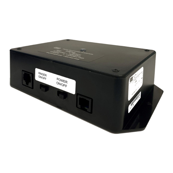
TI7000 TELEPHONE INTERFACE MODULE
(CONNECTOR VIEW)
STATUS LIGHT
BS INTERFACE CABLE
TO J201 on
NEXEO BASE STATION
RINGER
ON/OFF
RJ45
Fig. 2
TI7000
Mounting Holes
Base Station
Interface cable
Telephone Interface cable
TELEPHONE INTERFACE
CABLE TO TELEPHONE
JACK SPLITTER
POWER
ON/OFF
RJ11
HME# PUB-00215
Rev B 07/20/23
Advertisement

Subscribe to Our Youtube Channel
Related Manuals for HME TI7000


Summary of Contents for HME TI7000
- Page 1 (0.91 m)). Mount the TI7000 close to the Base Station. Mounting Holes Wall mount instructions: 1. Hold the TI7000 against the wall and mark the wall through the two mounting holes on each end of the unit (see Fig. 1).
- Page 2 SWITCH PORT set in the ON position, Switches 1, 3, and 4 are OFF. If using the TI7000 for EOS, switch #2 must be set in the OFF position (switches 1, 3, and 4 are also OFF). Fig. 6 © 2023 HM Electronics, Inc. All rights reserved.
- Page 3 Interface cable REMOTE SWITCHES DOORS TELEPHONE TELEPHONE TELEPHONE Note: Also, make sure the TI7000 DIP Switch has been JACK SPLITTER Telephone Interface cable set for EOS. See Note on page 2 and see Fig.6. Wall Port EOS BASE STATION SETTINGS:...
- Page 4 See NEXEO | HDX - Regulatory, Compliance, and Safety Guide online A copy of this guide and more can be found by scanning this QR code or going to: https://www.hme.com/qsr/drive-thru-user-manuals/ The HME logo and product names are registered trademarks of HM Electronics, Inc.
Need help?
Do you have a question about the TI7000 and is the answer not in the manual?
Questions and answers