Advertisement
Quick Links
The TI7000 provides the hardware necessary to link
®
a telephone to the NEXEO
HS7000 Headset to be used to answer incoming phone
calls.
TOOLS/EQUIPMENT REQUIRED (wall mounting only)
3
•
Drill and drill bits (~
/
•
Screwdriver (Phillips #2)
•
Safety Glasses
INSTALLATION AND SETUP
Note: The base station interface cable is short (3 ft
(0.91 m)) so mount the TI7000 close to the NEXEO
Base Station.
Wall mount instructions:
1. Hold the TI7000 against the wall and mark the wall
through the two mounting holes on each end of the
unit (see Fig. 1).
2. Drill two holes at the marked locations (avoid elec-
trical or plumbing obstructions).
3. Insert the included screw anchors until flush with
the wall.
4. Use a screwdriver to securely mount the TI7000 to
the wall using the included hardware.
Connections:
1. Unplug the store telephone from the wall port and
plug the included telephone jack splitter into the
same wall port.
2. Plug the telephone into one of the two ports on the
telephone jack splitter, see Fig 1.
3. Use the included telephone interface cable, plug
it into the other port on the telephone jack splitter
and connect the other end to the RJ11 port on the
TI7000. See Fig 1 and 2.
4. Open the Base Station and connect the included
base station interface cable from the RJ45 port
on the TI7000 to J201 on the base station PCBA
(see Fig. 3 for J201 location and Table 1 for J201
callout if necessary).
HM ELECTRONICS, INC.
2848 Whiptail Loop, Carlsbad, CA 92010 USA
Phone: 1-800-848-4468
Fax: 858-552-0172
Website: www.hme.com
Email: support@hme.com
Quick Reference Installation Guide
NEXEO | HDX™ TI7000 TELEPHONE INTERFACE
System. It allows one
16 th
inch (4.8 mm))
NEXEO BASE STATION
FRONT VIEW
TELEPHONE
TELEPHONE
JACK SPLITTER
Wall Port
Fig. 1
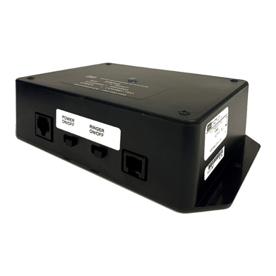
TI7000 TELEPHONE INTERFACE MODULE
(CONNECTOR VIEW)
STATUS LIGHT
BS INTERFACE CABLE
TO J201 on
NEXEO BASE STATION PCBA
NEXEO BASE STATION
POWER
ON/OFF
RJ45
J1300
USB
Type C
Reset button to
Fig. 2
reboot system
J2003
SW2001
PCBA Partial View
Serial
Debug
J200
USB
J1301
1
J600
J201
J800
1
1
Telephone
Timer Greet
Interface
Veh Detect 1
Fig. 3
TI7000
Mounting Holes
Base Station
Interface cable
Telephone Interface cable
TELEPHONE INTERFACE
CABLE TO TELEPHONE
JACK SPLITTER
1
1
RINGER
J1400
Ethernet
ON/OFF
J4501
J4500
Remote
J3000
J3200
Module 1
RJ11
J803
Early
Remote
J3400
Warnings
Module 2
1
Remote
J804
J3600
Module 3
Remote
Switches
Remote
1
J3800
Module 4
J805
Alert
Inputs
J1
1
GND
J802
J801
DC -
Veh Detect
1
1
Inputs
DC +
1
Timer Greet
Veh Detect 2
HME# PUB-00215
Rev A 01/06/23
Power
In
Advertisement

Subscribe to Our Youtube Channel
Related Manuals for HME NEXEO HDX TI7000


Summary of Contents for HME NEXEO HDX TI7000
- Page 1 Inputs DC + Telephone Timer Greet Timer Greet Interface Veh Detect 1 Veh Detect 2 Fig. 3 HM ELECTRONICS, INC. HME# PUB-00215 2848 Whiptail Loop, Carlsbad, CA 92010 USA Rev A 01/06/23 Phone: 1-800-848-4468 Fax: 858-552-0172 Website: www.hme.com Email: support@hme.com...
- Page 2 A copy of this guide and more can be found by scanning this QR code or going to: https://www.hme.com/qsr/drive-thru-user-manuals/ The HME logo and product names are registered trademarks of HM Electronics, Inc. © 2023 HM Electronics, Inc. All rights reserved.
Need help?
Do you have a question about the NEXEO HDX TI7000 and is the answer not in the manual?
Questions and answers