
Subscribe to Our Youtube Channel
Related Manuals for HME Clear-Com FIM-S222


Summary of Contents for HME Clear-Com FIM-S222
- Page 1 User Guide Clear-Com FIM-S222 User Guide Part Number: 399G132 Rev A.1 Date: 6/8/15...
-
Page 2: Table Of Contents
User Guide | FIM-S222 Table of Contents Document Reference ..................3 1.1 Important Safety Instructions ................4 1.2 Safety symbols ....................5 Introduction ....................6 Installing the FIM-S222 ................7 3.1 Unpacking ....................... 7 3.2 FIM-S222 System Configuration ................. 7 3.3 Selecting and Installing the Fiber-Optic Cable ............ -
Page 3: Document Reference
Clear-Com FIM-S222 User Guide Part Number: 399G132sRevision: A Legal Disclaimers Copyright © 2014-2015 HME Clear-Com Ltd. All rights reserved. Clear-Com and the Clear-Com logo are registered trademarks of HM Electronics, Inc. The software described in this document is furnished under a license agreement and may be used only in accordance with the terms of the agreement. -
Page 4: Important Safety Instructions
User Guide | FIM-S222 1.1 Important Safety Instructions Read these instructions. Keep these instructions. Heed all warnings. Follow all instructions. Do not use this apparatus near water. Clean only with dry cloth. Do not block any ventilation openings. Install in accordance with the manufacturer’s instructions. -
Page 5: Safety Symbols
User Guide | FIM-S222 1.2 Safety symbols Familiarize yourself with the safety symbols in Figure 1: Safety symbols. These symbols are displayed on the apparatus and warn you of the potential danger of electric shock if the system is used improperly. Figure 1-1: Safety symbols Note: Important. -
Page 6: Introduction
With a Clear-Com FIM-S222 System, you can connect intercom panels or interfaces to a central matrix using fiber-optic cables at distances of up to 12 miles (20 km). -
Page 7: Installing The Fim-S222
User Guide | FIM-S222 Installing the FIM-S222 3.1 Unpacking When you receive your Clear-Com FIM-S222 System, check to make sure you have received all components of the system. The following items make up a Clear-Com FIM-S222: FIM-S222 multiplexer/demultiplexer unit ... -
Page 8: Connecting Fiber-Optic Cable To The Fim-S222
User Guide | FIM-S222 Mark or tag the optical fibers when they are pulled, carefully avoiding the fiber tip, so that their identity is known at both ends. If there is confusion about the identity of the two fibers, shine a flashlight at one end of the fiber and look for light at the other end. -
Page 9: Connecting Audio/Data Cables To The Fim-S222
User Guide | FIM-S222 3.5 Connecting Audio/Data Cables to the FIM-S222 RJ-45 connectors on the FIM-S222 unit’s right side panel connect the unit to audio and data inputs and outputs, as shown in Figure 3-2. Two ports are provided, labeled PORT-1 and PORT-2. The data passing through these two ports is bi-directional. -
Page 10: Powering The Fim-S222
User Guide | FIM-S222 Figure 3-3 Wiring an FIM-S222 to Intercom Panels or Interfaces Figure 3-4 illustrates the CAT-5 and above cable pinout configuration. The maximum length for CAT-5 cables is 10,000 feet (3 km). Figure 3-4 CAT-5 Cable Pinout Diagram 3.6 Powering the FIM-S222 Power the FIM-S222 by plugging the supplied external power adapter into the mains power source, and then plugging the adapter output into the power supply connector on... -
Page 11: Compatibility With Fim-102D Interfaces
User Guide | FIM-S222 Power supply connector When power is first applied, you will notice that the LEDs on the left side panel flash for a few moments at random. When the power within the unit has stabilized, the left-most LED will illuminate at full intensity for a moment. -
Page 12: Using The Fim-S222
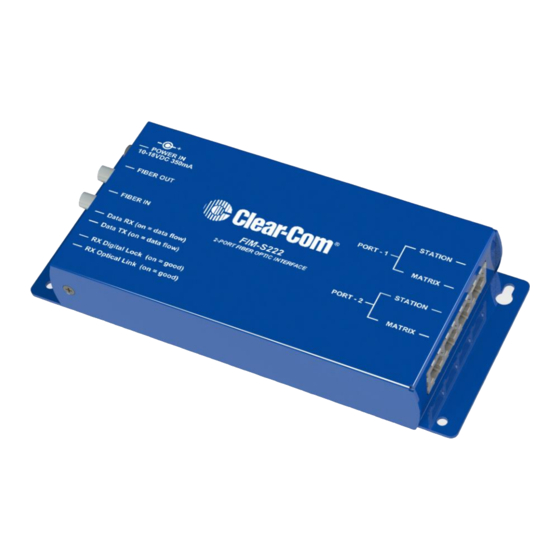
User Guide | FIM-S222 Using the FIM-S222 4.1 FIM-S222 Left Side Panel Connectors and Indicators Power supply connector Fiber Out (ST socket) Fiber In (ST socket) Data RX (on = data flow) Data TX (on = data flow) LEDs RX Digital lock (on = good) RX optical link (on = good) Figure 4-1 Left Side Panel of the FIM-S222 Fiber Out... -
Page 13: Fim-S222 Right Side Panel Connectors
4.3 Applications 4.3.1 Connecting Intercom Panels to the Central Matrix The Clear-Com FIM-S222 system transmits audio and data signals from 1 or 2 intercom panels or interfaces to the matrix frame through the process illustrated in Figure 4-3. The text below gives a step-by-step description of the signal processing that occurs as an intercom signal passes through the system. - Page 14 User Guide | FIM-S222 3. The first FIM-S222 unit then multiplexes (combines) the digital audio signals with the already-digital data signals Figure 4-3 Connecting Intercom Panels to the Central Matrix 4. The first FIM-S222 then converts the multiplexed digital signal into an optical signal. 5.
-
Page 15: Connecting Interface Modules To The Central Matrix
User Guide | FIM-S222 9. The second FIM-S222 unit then transmits the analog audio and digital data signals for each intercom panel to the central matrix over copper cable terminated with RJ-45 connectors. 10. The central matrix receives the intercom panels’ audio and data signals in the same format in which they were originally sent by the Matrix Plus 3 or Eclipse intercom panels CIRCUIT... -
Page 16: Using The Fim-S222 With The Ef-701M As A Stand-Alone Party Line Extender
User Guide | FIM-S222 Figure 4-4 Connecting Interface Modules to the Central Matrix 4.3.3 Using the FIM-S222 with the EF-701M as a Stand-Alone Party Line Extender Using a Clear-Com EF-701M at each end of an FIM-S222 set, you can extend Clear- Com or RTS 2-wire party line intercoms over a fiber-optic link independent of a matrix intercom system. -
Page 17: Maintaining The Fim-S222
User Guide | FIM-S222 Maintaining the FIM-S222 5.1 Troubleshooting Tips Listed below are some of the more common problems that you may experience, their possible causes and suggested solutions. POSSIBLE SYMPTOM CAUSE ACTION No operation, indicators No power. Make sure the external power all off. -
Page 18: Fim-1222 For Grass Valley Densité Frames
User Guide | FIM-S222 FIM-1222 for Grass Valley Densité Frames The functionality of the FIM-S222 is now available in the form of a card that plugs into a Grass Valley Densité-series frame. The FIM-1222 card occupies a single slot in the frame. It is sized for the 2RU Densité-2 frame, but optional extenders allow it to fit into 3RU Densité... -
Page 19: Rear Panels And Connectors
User Guide | FIM-S222 An alternative application uses FIM-1222 cards in Densité frames at both station and matrix ends of the system. 6.2 Rear panels and connectors Two rear panels are available for the FIM- 1222: FIM-1222-RP-SRP – station end ... -
Page 20: Connector Pinouts
User Guide | FIM-S222 6.2.1 Connector Pinouts The rear panel connectors have the following pinouts: FIM-1222-RP-SRP FIM-1222-MF-SRP Pin # STATION 1 & STATION 2 MATRIX 1 & MATRIX 2 RS-422 input + RS-422 output + RS-422 input – RS-422 output – Audio input + Audio output + Audio output +... -
Page 21: Local Control Panel Operation
User Guide | FIM-S222 6.3.2 Local Control Panel Operation Push the SELECT button on the FIM-1222 card edge (see section 6.3.1) to assign the local control panel to operate the FIM-1222. Use the control panel buttons to navigate through the menu, as described below. -
Page 22: Menu For Local Status Monitoring
User Guide | FIM-S222 6.3.3 Menu for local status monitoring The FIM-1222 reports its operational status to the frame’s on-board controller. Press the SELECT button on the FIM-1222 front card edge to assign the frame’s local control panel to the FIM-1222 ... - Page 23 User Guide | FIM-S222 Note that the information available through the menu may also be accessed remotely, if the frame is connected to a Grass Valley iControl system.
-
Page 24: Specifications
User Guide | FIM-S222 Specifications Audio Transmission Method Digital, TDM, 24-bit, 48k samples/sec Input Impedance 600 Ohms balanced Output Impedance 30 Ohms balanced Maximum Input Level (600 Ohms) +18 dBm (peak) Maximum Output Level (from 30 Ohms balanced) +18 dBm into 600 Ohms Frequency Response (@0 dBm from 50 Hz to 15 kHz) ±0.2 dB... - Page 25 User Guide | FIM-S222 Power Requirements Voltage 9-18 VDC WARNING: Absolute maximum voltage is 18 VDC. Equipment damage may occur at higher voltages. NOTICE ABOUT SPECIFICATIONS While Clear-Com makes every attempt to maintain the accuracy of the information contained in its product manuals, the information is subject to change without notice. Performance specifications included in this manual are design-center specifications and are included for customer guidance and to facilitate system installation.
-
Page 26: Compliance
User Guide | FIM-S222 Compliance FCC notice This device complies with Part 15 of the FCC rules. Operation is subject to the following two conditions: (1) This device may not cause harmful interference, and (2) This device must accept any interference received, including interference that may cause undesired operation. - Page 27 User Guide | FIM-S222 Instructions for Disposal of WEEE by Users in the European Union The symbol shown below is on the product or on its packaging which indicates that this product was put on the market after August 13, 2005 and must not be disposed of with other waste.
Need help?
Do you have a question about the Clear-Com FIM-S222 and is the answer not in the manual?
Questions and answers