Table of Contents
Advertisement
Quick Links
Advertisement
Table of Contents

Related Manuals for PaloAlto Networks PA-7500


Summary of Contents for PaloAlto Networks PA-7500
- Page 1 PA-7500 Next-Gen Firewall Hardware Reference docs.paloaltonetworks.com...
- Page 2 Alto Networks. A list of our trademarks can be found at www.paloaltonetworks.com/company/ trademarks.html. All other marks mentioned herein may be trademarks of their respective companies. Last Revised May 2, 2023 PA-7500 Next-Gen Firewall Hardware Reference 2023 Palo Alto Networks, Inc. ©...
-
Page 3: Table Of Contents
PA-7500 Series Firewall DPC LEDs................55 PA-7500 Series Firewall SFC LEDs................57 PA-7500 Series Firewall Maintenance............59 Replace a PA-7500 Series Firewall AC or DC Power Supply......... 60 Replace a PA-7500 Series Firewall Interface Card............62 Replace a PA-7500 Series Firewall Fan Assembly............67 Replace a PA-7500 Series Firewall System Drive.............70... - Page 4 Table of Contents Replace a PA-7500 Series Firewall Logging Drive............73 PA-7500 Series Firewall Specifications............75 PA-7500 Series Firewall Physical Specifications............... 76 PA-7500 Series Firewall Electrical Specifications............. 77 PA-7500 Series Firewall Component Electrical Specifications......77 PA-7500 Series Firewall Power Cord Types............77 PA-7500 Series Firewall Environmental Specifications........... 79 PA-7500 Series Firewall Compliance Statements........
-
Page 5: Before You Begin
Before You Begin Read the following topics before you install or service a Palo Alto Networks next-generation ® firewall or appliance.The following topics apply to all Palo Alto Networks firewalls and appliances except where noted. • Upgrade/Downgrade Considerations for Firewalls and Appliances •... -
Page 6: Upgrade/Downgrade Considerations For Firewalls And Appliances
20, then proceed with the upgrade. If the value the downgrade. If the is less than 20, then value is less than 20, contact support for then contact support for assistance. assistance. PA-7500 Next-Gen Firewall Hardware Reference 2023 Palo Alto Networks, Inc. ©... -
Page 7: Tamper Proof Statement
• The integrity of the warranty label on the firewall or appliance is not compromised. (PA-7000 Series firewalls only) PA-7000 Series firewalls are modular systems and therefore do not include a warranty label on the firewall. PA-7500 Next-Gen Firewall Hardware Reference 2023 Palo Alto Networks, Inc. ©... -
Page 8: Third-Party Component Support
Before You Begin Third-Party Component Support Before you consider installing third-party hardware, read the Palo Alto Networks Third-Party Component Support statement. PA-7500 Next-Gen Firewall Hardware Reference 2023 Palo Alto Networks, Inc. ©... -
Page 9: Product Safety Warnings
Mettez au rebut les batteries usagées conformément aux instructions. • I/O ports are intended for intra-building connections only and not intended for OSP (Outside Plant) connections or any network connections subject to external voltage surge events. PA-7500 Next-Gen Firewall Hardware Reference 2023 Palo Alto Networks, Inc. ©... - Page 10 Toutefois, vous devez le faire dans les 45 secondes et vous ne pouvez remplacer qu’un tiroir à la fois, sinon le circuit de protection thermique arrêtera le pare-feu. PA-7500 Next-Gen Firewall Hardware Reference 2023 Palo Alto Networks, Inc. ©...
- Page 11 à accès limité uniquement. Une zone à accès limité correspond à une zone dans laquelle l’accès n’est autorisé au personnel (de service) qu'à l'aide d'un outil spécial, PA-7500 Next-Gen Firewall Hardware Reference 2023 Palo Alto Networks, Inc.
- Page 12 • A suitably-rated DC mains disconnect device must be provided as part of the building installation. French Translation: Un interrupteur d'isolement suffisant doit être fourni pendant l'installation du bâtiment. PA-7500 Next-Gen Firewall Hardware Reference 2023 Palo Alto Networks, Inc. ©...
-
Page 13: Pa-7500 Series Firewall Overview
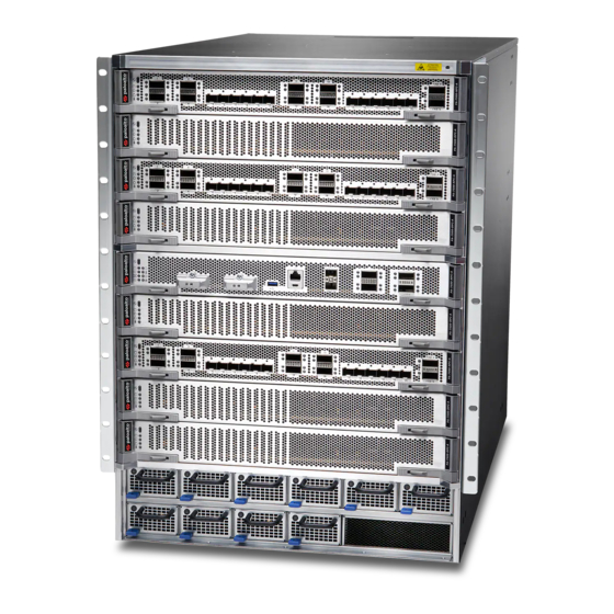
PA-7500 Series Firewall Overview The PA-7500 Series firewalls are high-performance modular firewalls designed for large enterprise environments. These multi-blade chassis can leverage either AC or DC power and use hot-swappable slot cards to allow for expansion as needs grow. There are a total of nine... -
Page 14: Pa-7500 Series Firewall Front And Back Panel Descriptions
• PA-7500 Series Front Panel • PA-7500 Series Back Panel PA-7500 Series Front Panel The following image shows the front panel of the PA-7500 Series firewall and the table describes each front panel component. Item Component Description Front slot cards... -
Page 15: Pa-7500 Series Back Panel
Connect Power to the PA-7500 Series Firewall. PA-7500 Series Back Panel The following image shows the back panel of the PA-7500 Series firewall and the table describes each back panel component. PA-7500 Next-Gen Firewall Hardware Reference 2023 Palo Alto Networks, Inc. - Page 16 Two slots that house Switch Fabric Cards (SFCs). One SFC must be installed while a second SFC can be installed for redundancy. View the PA-7500 Series Module and Interface Card Descriptions for more information on the slot cards and their components.
- Page 17 On the back panel of the chassis, the power supplies are numbered as follows: For more information on connecting power to the firewall, see Connect Power to the PA-7500 Series Firewall. PA-7500 Next-Gen Firewall Hardware Reference 2023 Palo Alto Networks, Inc.
-
Page 18: Pa-7500 Series Module And Interface Card Descriptions
PA-7500 Series Firewall Overview PA-7500 Series Module and Interface Card Descriptions The following topics list the components and features of each PA-7500 Series firewall interface card. • PA-7500 Series Firewall Management Processing Card (MPC) • PA-7500 Series Firewall Network Processing Card (NPC) •... - Page 19 You can configure HA2 (data link) on the HSCI ports or on NPC data ports. When configuring on dataplane ports, you must ensure that both the HA2 and HA2-Backup PA-7500 Next-Gen Firewall Hardware Reference 2023 Palo Alto Networks, Inc. ©...
-
Page 20: Pa-7500 Series Firewall Network Processing Card (Npc)
The Network Processing Card (NPC) provides the firewall with network connectivity. An NPC can be installed in slots 1, 2, 3, 4, 6, 7, 8, and 9. The following image shows the PA-7500 NPC and the table below describes each labeled component. -
Page 21: Pa-7500 Series Firewall Data Processing Card (Dpc)
The Data Processing Card (DPC) provides the firewall with additional processing power and capacity. A DPC can be installed in slots 1, 2, 3, 4, 6, 7, 8, and 9. The following image shows the PA-7500 DPC and the table below describes each labeled component. -
Page 22: Pa-7500 Series Firewall Switch Fabric Card (Sfc)
An SFC can be installed in one or both of the two back slots of the chassis. The second SFC is used for redundancy. The following image shows the PA-7500 SFC and the table below describes each labeled component. - Page 23 A small button that, with the help of a pin, can be used to reset the SFC and its associated front slot cards. Ejector Handles Handles that are used to insert replace the interface card. PA-7500 Next-Gen Firewall Hardware Reference 2023 Palo Alto Networks, Inc. ©...
- Page 24 PA-7500 Series Firewall Overview PA-7500 Next-Gen Firewall Hardware Reference 2023 Palo Alto Networks, Inc. ©...
-
Page 25: Pa-7500 Series Firewall Installation
After the firewall is installed in the rack (with all components installed), connect power, verify that the interface cards are functioning, and then connect the network and management cables. The PA-7500 Series firewalls ship with racking equipment and cables that enable you to install the firewall in your deployment environment. •... -
Page 26: Install The Pa-7500 Series Firewall In An Equipment Rack
PA-7500 Series Firewall Installation Install the PA-7500 Series Firewall in an Equipment Rack The following procedure describes how to install the PA-7500 Series firewall in an equipment rack. The PA-7500 chassis and the interface cards (MPC, NPC, DPC, and SFC) ship in separate boxes and it is recommended that you install the cards after you rack-mount the appliance. - Page 27 STEP 2 | Position the bottom edges of the fixed and adjustable brackets to the bottom of the 14 RU rack space reserved for the PA-7500. Align the slotted holes of the fixed mounting bracket PA-7500 Next-Gen Firewall Hardware Reference 2023 Palo Alto Networks, Inc.
- Page 28 Similarly, align the slotted holes in the adjustable mounting bracket to the holes on the rear of the equipment frame. PA-7500 Next-Gen Firewall Hardware Reference 2023 Palo Alto Networks, Inc.
- Page 29 (not provided) compatible with your equipment frame. Tighten the screws to their recommended torque value. The mounting brackets are designed for equipment frames that are up to 32” deep (81.3 cm). PA-7500 Next-Gen Firewall Hardware Reference 2023 Palo Alto Networks, Inc. ©...
- Page 30 STEP 4 | Use the provided 6-32 x 5/16 flathead screws to secure the adjustable bracket to the fixed bracket. A minimum of 6 screws are required for each side. PA-7500 Next-Gen Firewall Hardware Reference 2023 Palo Alto Networks, Inc. ©...
- Page 31 STEP 6 | Slide the PA-7500 on the brackets that were previously mounted to the equipment frame until the front mounting flanges of the PA-7500 are flush against the mounting surface of the equipment frame. PA-7500 Next-Gen Firewall Hardware Reference 2023 Palo Alto Networks, Inc.
- Page 32 PA-7500 Series Firewall Installation STEP 7 | Secure the PA-7500 to the equipment frame on both sides using 8 screws per bracket (not provided). The screws must be compatible with your equipment frame. PA-7500 Next-Gen Firewall Hardware Reference 2023 Palo Alto Networks, Inc.
- Page 33 PA-7500 Series Firewall Installation STEP 8 | Use the provided 8-32 x 3/8” Phillips panhead screws to secure the back side of the PA-7500 to the previously mounted brackets. PA-7500 Next-Gen Firewall Hardware Reference 2023 Palo Alto Networks, Inc. ©...
-
Page 34: Install A Pa-7500 Series Firewall Interface Card
PA-7500 Series Firewall Installation Install a PA-7500 Series Firewall Interface Card The Management Processing Card (MPC), Network Processing Card (NPC), and Data Processing Card (DPC) are installed on the front panel of the chassis. The process to install each of these interface cards is the same. - Page 35 Close the ejector handles to ensure that the card is secure in place. PA-7500 Next-Gen Firewall Hardware Reference 2023 Palo Alto Networks, Inc.
- Page 36 PA-7500 Series Firewall Installation PA-7500 Next-Gen Firewall Hardware Reference 2023 Palo Alto Networks, Inc. ©...
- Page 37 PA-7500 Series Firewall Installation PA-7500 Next-Gen Firewall Hardware Reference 2023 Palo Alto Networks, Inc. ©...
- Page 38 2. (SFC) Insert the blank into the back slot. Secure the blank in place by turning the two thumb tabs so that they lock into the chassis. PA-7500 Next-Gen Firewall Hardware Reference 2023 Palo Alto Networks, Inc. ©...
- Page 39 PA-7500 Series Firewall Installation To remove the blank, turn the thumb tabs so that it is unlocked from the chassis. Pull the blank outwards. PA-7500 Next-Gen Firewall Hardware Reference 2023 Palo Alto Networks, Inc. ©...
-
Page 40: Connect Power To The Pa-7500 Series Firewall
PA-7500 Series Firewall Installation Connect Power to the PA-7500 Series Firewall The PA-7500 Series firewall supports up to ten AC or DC power supplies. A minimum of four power supplies is required, while additional power supplies can be used to provide redundancy. -
Page 41: Connect Ac Power To The Pa-7500 Series Firewall
PA-7500 Series Firewall Installation Connect AC Power to the PA-7500 Series Firewall The following procedure describes how to connect AC power to the PA-7500 Series firewall. The AC power supplies support 100 to 240VAC power input. A minimum of four power supplies is required. - Page 42 PA-7500 Series Firewall Installation ensuring that each pair of power supplies is connected to its own circuit breaker. This ensures power redundancy and allows for planned electrical circuit maintenance. PA-7500 Next-Gen Firewall Hardware Reference 2023 Palo Alto Networks, Inc. ©...
-
Page 43: Connect Dc Power To The Pa-7500 Series Firewall
Connect DC Power to the PA-7500 Series Firewall The following procedure describes how to connect DC power to the PA-7500 Series firewall. The DC power supplies support 48 to 60VDC power input. A minimum of four power supplies is required. - Page 44 DC power source. Connect the black wire to the DC positive (RTN) terminal of your DC power source. Do this for each of the power supplies you are installing, ensuring that each PA-7500 Next-Gen Firewall Hardware Reference 2023 Palo Alto Networks, Inc.
- Page 45 DC power supplies. It is best to route the cables first and then plug the cables into the power supplies. PA-7500 Next-Gen Firewall Hardware Reference 2023 Palo Alto Networks, Inc. ©...
-
Page 46: View Power Statistics Of The Pa-7500 Series Firewalls
View Power Statistics of the PA-7500 Series Firewalls Use the following information to learn how to view active power statistics on a PA-7500 Series firewall to help you ensure power redundancy and to plan for growth. You can view the amount of power that each power supply is producing as well as the power rating for each hardware component. - Page 47 3. View the output for information on the status of each component and the current power rating. For example, the following table shows the CLI output (in table format) from a PA-7500 with four power supplies installed. The output shows each front slot (1 to 9), the installed power supplies and fan assemblies, the status of each component, the rated power consumption for each component, and the amount of power produced by each power supply.
-
Page 48: Connect Cables To The Pa-7500 Series Firewall
If you install two matching firewalls in a high availability configuration, you will also connect HA cables between the two appliances (see HA Links and Backup Links). The next image shows the PA-7500 firewall cable connections. PA-7500 Next-Gen Firewall Hardware Reference 2023 Palo Alto Networks, Inc. ©... -
Page 49: Pa-7500 Series Firewall Led Definitions
PA-7500 Series Firewall LED Definitions • Interpret the PA-7500 Series Firewall LEDs • Interpret the PA-7500 Series Firewall Interface Card LEDs • PA-7500 Series Firewall MPC LEDs • PA-7500 Series Firewall NPC LEDs • PA-7500 Series Firewall DPC LEDs •... -
Page 50: Interpret The Pa-7500 Series Firewall Leds
PA-7500 Series Firewall LED Definitions Interpret the PA-7500 Series Firewall LEDs The following table describes the definitions of the LEDs located on the power supplies and fan assemblies. For the interface card LED definitions, see Interpret the PA-7500 Series Firewall Interface Card LEDs. -
Page 51: Interpret The Pa-7500 Series Firewall Interface Card Leds
PA-7500 Series Firewall LED Definitions Interpret the PA-7500 Series Firewall Interface Card LEDs Consult the following topics to view the LED definitions of each interface card and its ports. • PA-7500 Series Firewall MPC LEDs • PA-7500 Series Firewall NPC LEDs •... - Page 52 PA-7500 Series Firewall LED Definitions Description High Availability • Green—The firewall is the active peer in an active/passive configuration. • Yellow—The firewall is the passive peer in an active/passive configuration. • Off—High availability (HA) is not operational on this firewall.
- Page 53 PA-7500 Series Firewall LED Definitions Description • Green—The power supply is operating normally. • Red—The power supply is present but is not working. The following table describes how to interpret the LEDs on the MPC ports. Description LOG-1 and LOG-2 (zQSFP) The zQSFP ports have four LEDs each;...
-
Page 54: Pa-7500 Series Firewall Npc Leds
PA-7500 Series Firewall LED Definitions PA-7500 Series Firewall NPC LEDs The following table describes how to interpret the status LEDs on a Network Processing Card (NPC). Description Service Allows a remote administrator to illuminate the LED on a specific front-slot card so an on-site technician can locate the card. -
Page 55: Pa-7500 Series Firewall Dpc Leds
PA-7500 Series Firewall LED Definitions Description See the PA-7500 Series Firewall Environmental Specifications for the operating temperature range. The following table describes how to interpret the LEDs on the NPC ports. Description SFP, SFP+, and SFP28 The SFP, SFP+ and SFP28 ports have four LEDs each;... - Page 56 PA-7500 Series Firewall LED Definitions Description Service Allows a remote administrator to illuminate the LED on a specific front-slot card so an on-site technician can locate the card. • Off—The firewall is operating normally. • Blue—The firewall is instructed by the CLI or Web Interface to enable this LED.
-
Page 57: Pa-7500 Series Firewall Sfc Leds
PA-7500 Series Firewall LED Definitions PA-7500 Series Firewall SFC LEDs The following table describes how to interpret the status LEDs on a Switch Fabric Card (SFC). Description Service Allows a remote administrator to illuminate the LED on a specific front-slot card so an on-site technician can locate the card. - Page 58 PA-7500 Series Firewall LED Definitions Description Temperature • Green—The firewall temperature is normal. • Yellow—The firewall temperature is outside tolerance levels. See the PA-7500 Series Firewall Environmental Specifications for the operating temperature range. PA-7500 Next-Gen Firewall Hardware Reference 2023 Palo Alto Networks, Inc.
-
Page 59: Pa-7500 Series Firewall Maintenance
PA-7500 Series Firewall Maintenance The following topics describes how to replace field-serviceable components on a PA-7500 Series firewall. For an overview of the hardware components, see PA-7500 Series Firewall Overview. • Replace a PA-7500 Series Firewall AC or DC Power Supply •... -
Page 60: Replace A Pa-7500 Series Firewall Ac Or Dc Power Supply
Replace a PA-7500 Series Firewall AC or DC Power Supply The following instructions describe how to replace a power supply in a PA-7500 Series firewall. STEP 1 | Put the provided ESD wrist strap on your wrist ensuring that the metal contact is touching your skin. - Page 61 It is best to route and secure the cable first and then plug the cable into the power supply. PA-7500 Next-Gen Firewall Hardware Reference 2023 Palo Alto Networks, Inc. ©...
-
Page 62: Replace A Pa-7500 Series Firewall Interface Card
ESD ports located on the appliance before handling ESD sensitive hardware. STEP 2 | (MPC only) Ensure that the PA-7500 firewall is powered off and that the fans are not still spinning. PA-7500 Next-Gen Firewall Hardware Reference 2023 Palo Alto Networks, Inc. - Page 63 • (SFC) Push the ejector tabs on the card away from the center, prompting a click. This will allow the ejector handles to rotate outward and unlock the card. PA-7500 Next-Gen Firewall Hardware Reference 2023 Palo Alto Networks, Inc. ©...
- Page 64 PA-7500 Series Firewall Maintenance PA-7500 Next-Gen Firewall Hardware Reference 2023 Palo Alto Networks, Inc. ©...
- Page 65 PA-7500 Series Firewall Maintenance STEP 4 | Grip the ejector handles and gently pull the card out of its slot. PA-7500 Next-Gen Firewall Hardware Reference 2023 Palo Alto Networks, Inc. ©...
- Page 66 Boot the appliance with the new MPC installed. When prompted, log in and reset the firewall to factory default settings. STEP 7 | (MPC only) Restore your previous device configuration. PA-7500 Next-Gen Firewall Hardware Reference 2023 Palo Alto Networks, Inc. ©...
-
Page 67: Replace A Pa-7500 Series Firewall Fan Assembly
PA-7500 Series Firewall Maintenance Replace a PA-7500 Series Firewall Fan Assembly The PA-7500 Series firewall can support up to fifteen dual-rotor, single fan assemblies on its rear side. Each single fan assembly can be individually removed and replaced. When a fan is functioning as expected, the LED on the fan assembly will be green. - Page 68 LED on the Management Processing Card (MPC). The individual fan assembly LED shows green if it is functioning as expected. Similarly, the fan LED on the MPC also PA-7500 Next-Gen Firewall Hardware Reference 2023 Palo Alto Networks, Inc.
- Page 69 You can also view the status of the fan trays by entering the following command: admin@PA-7500> show system environmentals fan-tray To view the status of each fan on a fan tray, run the following command: admin@PA-7500>...
-
Page 70: Replace A Pa-7500 Series Firewall System Drive
PA-7500 Series Firewall Maintenance Replace a PA-7500 Series Firewall System Drive The Management Processing Card (MPC) features a pair of Solid State Drives (SSDs) containing the files of the PA-7500 Series firewall. The following procedure describes how to replace the SSD in the MPC. - Page 71 Remove the failed drive from the RAID 1 array. In this example, run the following command to remove drive Sys1 from the array: admin@PA-7500> request system raid remove sys1 STEP 3 | Confirm that the failed drive is removed from all partitions. In the following output of the show system raid detail, you see that drive id Sys1 is now missing from all partitions.
- Page 72 ESD ports located on the chassis. STEP 13 | Slide the interface card back into its slot. See Install a PA-7500 Series Firewall Interface Card for more information. PA-7500 Next-Gen Firewall Hardware Reference 2023 Palo Alto Networks, Inc.
-
Page 73: Replace A Pa-7500 Series Firewall Logging Drive
PA-7500 Series Firewall Maintenance Replace a PA-7500 Series Firewall Logging Drive The Management Processing Card (MPC) contains two slots for logging drives. The following procedure describes how to install or replace a logging drive. STEP 1 | Attach an ESD strap to your wrist and plug the other end in to the ESD port location on the chassis. - Page 74 Executing this command will delete all data on the drive being added. Adding the logging drive can take a few minutes. Use admin@PA-7500> show system disk details to check the status. The Reason field displays Admin enabled when the process is complete.
-
Page 75: Pa-7500 Series Firewall Specifications
PA-7500 Series Firewall Specifications • PA-7500 Series Firewall Physical Specifications • PA-7500 Series Firewall Electrical Specifications • PA-7500 Series Firewall Component Electrical Specifications • PA-7500 Series Firewall Power Cord Types • PA-7500 Series Firewall Environmental Specifications... -
Page 76: Pa-7500 Series Firewall Physical Specifications
PA-7500 Series Firewall Specifications PA-7500 Series Firewall Physical Specifications The following table describes the PA-7500 Series firewall physical specifications. Specification Value Rack units—14RU Rack units Dimensions Chassis • Height—24.4" (61.98 cm) • Depth—31.0" (78.74 cm) • Width—17.4" (44.20 cm) Front slot card (MPC, DPC, and NC) •... -
Page 77: Pa-7500 Series Firewall Electrical Specifications
• Output Power— TBD PA-7500 Series Firewall Power Cord Types The PA-7500 Series firewalls ship with four AC or four DC power supplies by default. You can order up to six additional power supplies (ten total) and power cords are included with each power supply. - Page 78 Power Cord, North America, 15A, 250V, IEC C19 to IEC C14, 10ft PAN-PWR-C19-US-120V Power Cord, North America, 15A, 125V, C19 to NEMA 5-15P, 10ft PAN-PWR-C19-JP-120V Power Cord, Japan, 15A, 125V, JISC8303 to C19, 10ft, PSE Certified PA-7500 Next-Gen Firewall Hardware Reference 2023 Palo Alto Networks, Inc. ©...
-
Page 79: Pa-7500 Series Firewall Environmental Specifications
PA-7500 Series Firewall Specifications PA-7500 Series Firewall Environmental Specifications The following table describes PA-7500 Series firewall environmental specifications. Specification Value Operating temperature range 0° to 50°C (32°F to 122°F) Storage temperature range -20° to 70°C (-4°F to 158°F) Humidity 5% to 90% non-condensing... - Page 80 PA-7500 Series Firewall Specifications PA-7500 Next-Gen Firewall Hardware Reference 2023 Palo Alto Networks, Inc. ©...
-
Page 81: Pa-7500 Series Firewall Compliance Statements
Our products meet standards for product safety and electromagnetic compatibility when used for their intended purpose. To view compliance statements for the PA-7500 Series firewalls, see Compliance Statements. -
Page 82: Compliance Statements
• NEBS Requirements The following lists the Network Equipment Building System (NEBS) requirements for PA-7500 Series firewalls. • The firewall is intended to be installed in a Network Telecommunication Facility (Central Office) as part of a Common Bonding Network (CBN) or Isolated Bonding Network (IBN). - Page 83 PA-7500 Series Firewall Compliance Statements • BSMI EMC Statement—User warning: This is a Class A product. When used in a residential environment it may cause radio interference. In this case, the user will be required to take adequate measures. • Manufacturer—Flextronics International.
- Page 84 PA-7500 Series Firewall Compliance Statements PA-7500 Next-Gen Firewall Hardware Reference 2023 Palo Alto Networks, Inc. ©...
Need help?
Do you have a question about the PA-7500 and is the answer not in the manual?
Questions and answers