Table of Contents
Advertisement
Quick Links
Advertisement
Table of Contents

Related Manuals for jost JSK36D


Summary of Contents for jost JSK36D
- Page 1 JSK36D Air Release Installation and operating instructions...
- Page 2 Table of contents MUB 002 013 M30 (REV--) 02-2024...
-
Page 3: Table Of Contents
4.4 Manual opening in an emergency if the remote control fails............... 17 5 Maintenance..............19 5.1 Lubrication instructions (supplementary to the standard JSK36D)............19 5.2 Adjusting the locking mechanism (supplementary to standard JSK36D)..........20 6 Recycling............... 22 MUB 002 013 M30 (REV--) 02-2024... -
Page 4: Explanation Of Symbols
Explanation of symbols WARNING! Means that death, serious physical injury or significant material damage can occur if the relevant safety instruc- tions are not followed. ATTENTION! Means that slight physical injury or material damage can occur if the relevant safety instructions are not fol- lowed. -
Page 5: General Product Information
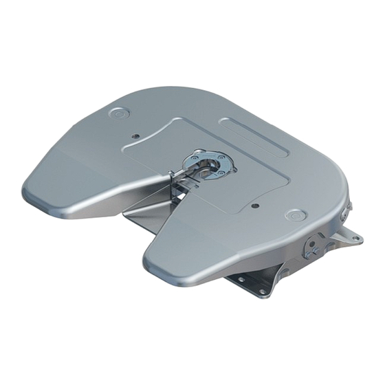
General product information The JSK36D Air Release is a pneumatically activated version of the ADVICE! JSK36D standard fifth wheel coupling (ECE 55R 01 0301), with the same load data and heights. This version differs from the stan- All other and more detailed information not... - Page 6 General product information Diagram of “JSK36D Air Release” version (closed and locked) Rope with handle Sensor Safety latch Pneumatic cylinder MUB 002 013 M30 (REV--) 02-2024...
-
Page 7: Installation
Installation General installation instructions In the JSK36D “PNFA” version, the tipping angle may need to be restricted at the front in the direction of travel, depending on the To secure the JSK36D Air Release (in accordance with Regulation vehicle body. It is essential to check this before use, especially ECE R55 01) to the vehicle chassis, make sure that all the fastening when the height is low (e.g. -
Page 8: Installing The Tilt Stop
Installation Installing the tilt stop Installation direction arrow 1. Mount the tilt stop (2) on the front left-hand side, on the left pedestal (1), on the side with only two holes in the foot. 2. Pay attention to the installation direction arrow (4), i.e. arrow in direction of travel. -
Page 9: Installing The Remote Display
Installation Installing the remote display 1. Connect the indicator light (2) to the sensor (1). Use Red and Black coloured wires (with ferrules). 2. Connect the series resistor (3) as shown in the diagram. 3. Connect the remote display circuit to the vehicle’s on-board electrical system. - Page 10 Installation ADVICE! ADVICE! Any combination of switching voltage and switch- The remote display must be positioned in close ing current must not exceed the max. switching proximity to the remote control. capacity. All electronic components must be protected For the device to function, the series resistor (3) against harmful environmental influences such as must be designed in line with the sensor (1) and moisture and corrosion.
-
Page 11: Installing The Remote Control
Installation Installing the remote control ADVICE! The fifth wheel coupling must be clearly visible from the remote control device. To make sure the second safety latch resets, the rope mechanism must not be obstructed. The remote control must bear a label indicating and explaining its function. - Page 12 Installation Compressed air quality Compressed Max. 15 bar air network Min. 5 bar (main air) Compressed air quality according to ISO 8573-1 ≙ ≤ 5 µm Solids Particle size/density ≙ -40 °C Water Dew point ≙ ≤ 5 mg/m mg/m Quality classes ATTENTION! Remove the filter (on the front) from the pneu-...
-
Page 13: Operation
Operation Open/closed status – open and unlocked Remote display (1): no light, or lights up red Lever (3) is visibly extended Remote display Lever is protruding, in open position Second lock (latch) open MUB 002 013 M30 (REV--) 02-2024... -
Page 14: Open/Closed Status - Closed And Locked, Pre-Departure Inspection
Operation Open/closed status – closed and locked, pre-departure inspection Remote display (1): lights up green ADVICE! Perform a pull test on the second lock (2): latch must move under tension The light must indicate “off-on-off-on” during the rope pull test. Remote display Lever in locked position Lever (3) is in locked position... -
Page 15: Opening The Coupling To Uncouple A Semi-Trailer
Operation Opening the coupling to uncouple a semi-trailer Procedure 1. Undo the lock to release the On/Off switch. 2. Pull the rope until the light goes out. Keep the rope pulled. ✓ The safety latch is now open. 3. Activate the cylinder while pulling the rope. ✓... - Page 16 Operation 4. After uncoupling A Return to the remote control and switch off pressure to the cylinder. B Secure the remote control to protect from unauthorised access. ATTENTION! Check the status of the locking mechanism before start- ing any journey, see 4.1 "Open/closed status – open and unlocked", page 13.
-
Page 17: Manual Opening In An Emergency If The Remote Control Fails
Operation Manual opening in an emergency if the remote control fails If the pneumatic opening mechanism is not functioning or in an emergency, the locking mechanism can be opened manually. We recommend wearing work gloves to make this easier. Two persons are required for this process. - Page 18 Operation Procedure 1. Pull the rope (1) to release the mechanism, see "Open/closed status – open and unlocked", page 13. 2. Using a suitable tool*, push the lever (2) out of the locking edge: 2.1: Insert the tool in the cutout and find the edge of the locking lever.
-
Page 19: Maintenance
Maintenance Lubrication instructions (supplementary to the standard Grease specification JSK36D) We recommend JOST high-performance lubricant (Art. No. SKE 013 440 000). ADVICE! For all other maintenance instructions, please refer to Installation & Operating Manual JSK36/37. Guide blocks Lever fulcrums Lever guide Recommended after every 50,000 km or as needed (e.g. -
Page 20: Adjusting The Locking Mechanism (Supplementary To Standard Jsk36D)
Maintenance Adjusting the locking mechanism (supplementary to standard JSK36D) ADVICE! The locking mechanism can only be adjusted using the JOST setting master for fifth wheel coupling SKE008630000. Bolt Locking lever MUB 002 013 M30 (REV--) 02-2024... - Page 21 6. Move the locking bar into its end position by gently knocking the locking lever (2) towards the centre of the vehicle. Make sure that the front edge of the JOST setting master does not lift up off the fifth wheel coupling plate. The entire surface of...
-
Page 22: Recycling
Recycling At the end of their useful life, all JOST products must be sorted by material and disposed of in an environmentally responsible manner. Check whether JOST products, spare and wear parts can be recycled before disposal. Recycle as many parts as possible. - Page 24 Member of JOST World JOST, Germany, Tel. +49 6102 295-0, tkd-technik@jost-world.com, www.jost-world.com MUB 002 013 M30 (REV--) 02-2024 • 2.0 1210299...
Need help?
Do you have a question about the JSK36D and is the answer not in the manual?
Questions and answers