Table of Contents
Advertisement
Quick Links
UM9180/1.0
May 2024
Features
•
Complete demonstration platform for the DRM1000
DRM/AM/FM Broadcast Receiver Module
•
Antenna connections for MF, HF or VHF
•
Push-button selection of: MF/HF/VHF bands, AM/FM/DRM
modes, frequency scan, station, volume up and down, storage
of up to four saved stations
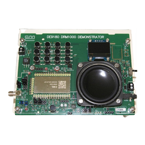
Figure 1 - Demonstration platform for the DRM1000 DRM/AM/FM Broadcast Receiver Module
1
Brief Description
The DE9180 is a compact demonstration platform that allows the functionality of the DRM1000 AM/FM Broadcast Receiver
Module to be easily demonstrated. The DRM1000 module is supplied soldered directly to the PCB, as it would be in an end-
product.
The DE9180 provides a full complement of inputs, outputs, and controls to allow the performance of the DRM1000 to be
assessed. Included are external power supply connector, headphone socket, connection for an external HF/VHF antenna,
connection for an external MF antenna, loudspeaker, battery holder and 16x2-character OLED display. Also included is a
12-button keypad that provides for adjustment of volume level (up and down), station selection, frequency band selection,
four pre-set station memory buttons, frequency scan, and other user functions.
A separate ferrite rod antenna may be mounted on the underside of the DE9180.
This document refers to the latest version of the DE9180 when used with a DRM1000 module loaded with the latest
firmware.
© 2024 CML Microsystems Plc
COMPANY CONFIDENTIAL
USER MANUAL
•
•
•
CONTENTS
Can operate from 3 AA alkaline batteries or
4.5V dc power supply
OLED user display
Built-in 2-inch loudspeaker and headphone
output
Advertisement
Table of Contents

Related Manuals for CML Microcircuits DE9180


Summary of Contents for CML Microcircuits DE9180
- Page 1 Module to be easily demonstrated. The DRM1000 module is supplied soldered directly to the PCB, as it would be in an end- product. The DE9180 provides a full complement of inputs, outputs, and controls to allow the performance of the DRM1000 to be assessed. Included are external power supply connector, headphone socket, connection for an external HF/VHF antenna, connection for an external MF antenna, loudspeaker, battery holder and 16x2-character OLED display.
-
Page 2: Table Of Contents
Evaluation Kit for DRM1000 DE9180 Brief Description ............................... 3 History..................................2 Block Diagrams ................................. 3 Preliminary Information ............................4 Laboratory Equipment............................... 4 4.1.1 Power Supply ..................................4 Handling Precautions ................................ 4 4.2.1 SSD Devices ..................................4 4.2.2 Contents – Unpacking ............................... 4 Approvals................................... - Page 3 Figure 1 - Demonstration platform for the DRM1000 DRM/AM/FM Broadcast Receiver Module ............3 Figure 2 - DRM1000 Block Diagram ..............................3 Figure 3 - DE9180 Kit Block Diagrams ..............................3 Figure 4 - Typical Connections for DE9180 ............................5 Figure 5 - PCB Layout: Top ..................................
-
Page 4: History
Demonstration Kit for DRM1000 DE9180 History Version Changes Date First Approved Release May 2024 © 2024 CML Microsystems Plc UM9180/1.0... -
Page 5: Brief Description
Demonstration Kit for DRM1000 DE9180 Block Diagrams Figure 2 - DRM1000 Block Diagram Figure 3 - DE9180 Kit Block Diagrams © 2024 CML Microsystems Plc UM9180/1.0... -
Page 6: Preliminary Information
500 mA. There is also a battery connector J2. Both inputs are reverse polarity protected using a series diode. Note: Do not connect a power supply to the DE9180 if batteries are inserted as this may cause component damage. Handling Precautions This product is designed for use in office and laboratory environments. -
Page 7: Operation
Select the frequency band required using the MF/HF/VHF button. The display will show the selected band. On first use with DRM press the AM/FM/DRM mode button to select DRM in the display. Place the DE9180 in a location where there is good radio reception (e.g. outdoors or close to a window) and press the SCAN button for at least 2 seconds. -
Page 8: Signal Lists
Demonstration Kit for DRM1000 DE9180 Signal Lists Table 1 - User Connector Pinouts USER CONNECTOR PINOUTS Connector Connector Signal Signal Description Ref. Pin No. Name Type 4.5 V Power supply input Power supply ground Battery + Battery - I2S_DATA_CS (DRM1000 future option) - Page 9 Demonstration Kit for DRM1000 DE9180 Table 2 - Test Points TEST POINTS Test Point Typical Description Ref. Measurement +4.5 V Input power test + 3.3 V VCC test +3.3 V RESETN J8 -1 Line level audio test output J8-2 Audio ground...
-
Page 10: Circuit Schematics And Board Layouts
Demonstration Kit for DRM1000 DE9180 Circuit Schematics and Board Layouts For clarity, the circuit schematic diagrams are available as separate high-resolution files, which can be downloaded from the CML website. The layouts for each side of the PCB are shown in the following two diagrams. -
Page 11: Detailed Description
2” speaker and headphone output Hardware Description Full details of the DRM1000 module is contained within its own separate datasheet. The DE9180 is assembled on a 136 mm x 103 mm, 1.6 mm thick 4-layer PCB (reference PCB780F), using FR4 / VT481 2116 dielectric. -
Page 12: Display And Control
A low level, single ended LOUT signal is also available at J8. Adjustments and Controls The DE9180 provides adjustments and control via a switch matrix as follows. Table 6 - Switch Matrix Switch Matrix... - Page 13 Demonstration Kit for DRM1000 DE9180 Table 7 - Button Functions Button Functions Button name Function: short press < 0.5s Function: long press ≥ 2s VOL+ Increase volume by one step Increase volume continuously while held VOL- Decrease volume by one step...
-
Page 14: Application Information
Application Information 8.3.1 Ferrite Rod Antenna A Ferrite Rod antenna may be fitted to the underside of the DE9180 for MF band reception. This optional ferrite rod offers two possible configurations: • A single winding connected to ANT1 (ANT_P & ANT_N), pins 1 and 2 and is tuned via the DRM1000 internal capacitor bank via R21/R22. -
Page 15: Troubleshooting
DE9180 Troubleshooting The DE9180 is a complex system. If incorrectly programmed or modified, results will be at variance from datasheet performance. Please study the DRM1000 datasheet, along with the associated schematics and layout drawings for these carefully when troubleshooting. This section provides suggestions to help users resolve application issues they might encounter. -
Page 16: Performance Specification
Demonstration Kit for DRM1000 DE9180 Performance Specification Electrical Performance 9.1.1 Absolute Maximum Ratings Exceeding these maximum ratings can result in damage to the Demonstration Kit. Table 9 - Absolute Maximum Ratings Absolute Maximum Ratings Min. Max. Units Supply (V Current into or out of V... - Page 17 Demonstration Kit for DRM1000 DE9180 CML does not assume any responsibility for the use of any circuitry described. No IPR or circuit patent licences are implied. CML reserves the right at any time without notice to change the said circuitry and any part of this product specification. Evaluation kits and demonstration boards are supplied for the sole purpose of demonstrating the operation of CML products and are supplied without warranty.
Need help?
Do you have a question about the DE9180 and is the answer not in the manual?
Questions and answers