Table of Contents
Advertisement
Quick Links
CML Microcircuits
COMMUNICA TION SEMICONDUCTORS
UM9720/1 March 2013
Features
CMX972 Quadrature 20-300MHz
Demodulator
Options for on-chip PLL or External LO
Sources
1
Brief Description
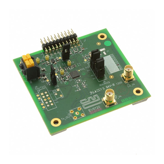
The EV9720 is an Evaluation Kit designed for evaluating and demonstrating the capabilities of the
CMX972 integrated circuit. All the circuits necessary to demonstrate the facilities provided by the IC, such
as matching circuits, power supply regulators, etc are provided on the EV9720 board. Note that as the
EV9720 shares a common pcb with the EV9730, the pcb will not be fully populated.
A C-BUS interface connector is provided for control of the EV9720 by a host microcontroller or CML
PE0002 interface card.
2013 CML Microsystems Plc
Evaluation Kit
C-BUS Interface to Host µC
Easy Interfacing to PE0601-xxx
EV9720
User Manual
Provisional Issue
Advertisement
Table of Contents

Related Manuals for CML Microcircuits EV9720


Summary of Contents for CML Microcircuits EV9720
-
Page 1: Brief Description
CMX972 integrated circuit. All the circuits necessary to demonstrate the facilities provided by the IC, such as matching circuits, power supply regulators, etc are provided on the EV9720 board. Note that as the EV9720 shares a common pcb with the EV9730, the pcb will not be fully populated. -
Page 2: Table Of Contents
Approvals ....................5 Quick Start ......................6 Hardware/Software Installation (for PE0002) ..........6 First – Initial Setup - EV9720 Quadrature IF Demodulator ....... 6 4.2.1 Make External Connections and Apply Power ......6 Second – Configure - EV9720 Quadrature IF Demodulator ..... 7 4.3.1... - Page 3 Page Figure 1 EV9720 Block Diagram ........................4 Figure 2 USB Driver Installation Message Box .....................6 Figure 3 Typical Connections for EV9720 as a Quadrature IF Demodulator ..........7 Figure 4a PCB Layout: top ..........................13 Figure 5 Reset Dialog Box ..........................16 Figure 6 Product Selection Dialog Box ......................16 Figure 7 The CBUS Control Tab .........................17...
-
Page 4: Block Diagram
External Resonator & VCOP1 Varactors VCOP2 OA1N LO_IN_2 Divide OA1P RXLO 2 or 4 RXIP RXIN Offset Adj. IF_IN IFIN RXQP Offset RXQN Regulator Adj. Power RXI/RXQ (J8) Regulator Figure 1 EV9720 Block Diagram 2013 CML Microsystems Plc UM9720/1... -
Page 5: Preliminary Information
3.1.2 Control Interface To use the EV9720, the user will need a mechanism to send and receive data and commands via the C-BUS host microcontroller interface on the CMX972, which is brought out on connector J7. The CMX972 datasheet gives details of the registers and commands. -
Page 6: Quick Start
4.2.1 Make External Connections and Apply Power An example of typical connections to the EV9720 is shown in Figure 3. Perform the following steps in sequence: 1. Connect test leads as shown in Figure 3, except the power to J6. -
Page 7: Second - Configure - Ev9720 Quadrature If Demodulator
4.3.1 EV9720 Configuration The following steps should be undertaken to configure the EV9720 to receive at 45MHz with an I/Q output. Set the applied signals and register values as shown in the following table. Note: Setting the CMX972 registers requires the use of the PE0002 host connected as above. -
Page 8: Third - Operate - Ev9720 Quadrature If Demodulator
Third – Operate - EV9720 Quadrature IF Demodulator Following the configuration procedures given in sections 4.2 and 4.3, the EV9720 should be operating as a receiver at 45MHz. Various evaluation tests can now be performed. 2013 CML Microsystems Plc... -
Page 9: Signal Lists
Evaluation Kit for CMX972 EV9720 Signal Lists The input power supply connection is via a 2-way snap socket J6. J2, J3 and J5 are RF signals and use SMA 50 Ohm sockets. J8 is a 10-pin header for differential RXI/RXQ modulation outputs from the demodulator. - Page 10 C-BUS Clock. Spare pin. Leave unconnected. RDATA C-BUS Data Output Spare pin. Leave unconnected. IRQN Interrupt request - if required. Not used, so remains unconnected on EV9720. GNDD Power Connection to Digital Ground. GNDD Power Connection to Digital Ground. Spare pin. Leave unconnected.
- Page 11 Evaluation Kit for CMX972 EV9720 The differential output I/Q signals from the demodulator (interface connector J8) are described in Table 3, along with the connections for single ended I/Q outputs, by using the general purpose op-amps, in Table 4. CONNECTOR PINOUT for J8...
- Page 12 Note that the voltages are typical for their active state. As the EV9720 shares a common pcb with the EV9730, the pcb will not be fully populated. In particular, connectors J2, J9, along with trimpot VR1, are not fitted. The pcb pads for J4 are underneath the board.
-
Page 13: Circuit Schematics And Board Details
Evaluation Kit for CMX972 EV9720 Circuit Schematics and Board Details For clarity, circuit schematics are available as a separate high-resolution file available from the CML web site as part of the support files package. The layout on each side is shown in Figure 4, below. - Page 14 Evaluation Kit for CMX972 EV9720 LO_IN_2 70.000 mm Figure 4b PCB Layout: bottom 2013 CML Microsystems Plc UM9720/1...
-
Page 15: Detailed Description
7.1.2 Oscillator The EV9720 provides components to use the VCO amplifier and PLL contained within the CMX972 device. As supplied, the resonator circuit (L4, C21, C20, C25, D1, D2) is configured for 180MHz operation with a tuning sensitivity of approximately 8MHz/V. The oscillator is usable up to about 1GHz, for further details consult the CMX972 datasheet. -
Page 16: Pc Control Software Description
The EV9720 itself does not require any embedded firmware, however, it does require C-BUS control from an external microcontroller. The CML product, PE0002, can be used with the EV9720 and PC software files (‘ES9700xx.zip’). To use the software, connect the EV9720 as shown in Figure 3. -
Page 17: The C-Bus Control Tab
Evaluation Kit for CMX972 EV9720 Once the initialisation and kit selection process is complete, one of four tabs can be selected, as shown in Figure 7 to Figure 10. The four tabs represent a particular set of registers or a particular function of the CMX972. -
Page 18: The Registers Tab
Evaluation Kit for CMX972 EV9720 ;If using C-BUS port 2 then use the following lines register 2 RESET 0 device 2 copy 0 *RESET 7.2.2 The Registers Tab The Registers tab gives the user access to the general control, Rx control and Rx mode registers, see Figure 8. -
Page 19: The Script Handler Tab
The script language is documented separately in the “Script Language Reference” document, which can be downloaded with the PE0002 support package from the CML website. Control of the EV9720 does not require the use of script files. 2013 CML Microsystems Plc... - Page 20 Evaluation Kit for CMX972 EV9720 Figure 10 The Script Handler Tab To select a script file, click on the ‘Select Script’ button. The Open File Dialog is displayed. Browse and select the script file. The folder that contains the script file will be the working folder of the script (i.e.
-
Page 21: Evaluation Tests
Evaluation Kit for CMX972 EV9720 7.3 Evaluation Tests The EV9720 is intended to allow evaluation and demonstration of the CMX972 device. The following is a list of tests which can be performed, along with the typical EV9720 performance. 7.3.1 Quadrature IF Demodulator 7.3.1.1 I/Q Signals Apply a LO signal (J3) of 90MHz, -10dBm and a RF signal (J5) of 45.002MHz, -53dBm. - Page 22 7.3.1.2 Noise Figure By applying a –100dBm signal to the EV9720 receiver input (J5) it is easy to evaluate the system noise figure by measuring the signal to noise on either I/Q output. For example, apply a LO signal (J3) of 90MHz, -10dBm and a RF signal (J5) of 45.002MHz, -100dBm.
-
Page 23: Troubleshooting
‘ES9700xx.exe’ software Faulty USB port or cable. Check USB cable to your PC. fails to run correctly and reports PE0002 or EV9720 is not powered Power up PE0002 (5.0V) and an error during start up. up during start up. EV9720 (7.2V). -
Page 24: Pll/Vco Operation
Evaluation Kit for CMX972 EV9720 7.4.3 PLL/VCO Operation Error Observed Possible Cause Remedy PLL does not lock. VCO or PLL is not enabled. Check values of PLL registers M and R Divider setting are incorrect. $2A to 2D. Check general control (Lock detect bit = ‘0’). -
Page 25: Performance Specification
V pins +200 Current into or out of any other connector pin 8.1.2 Operating Limits Correct operation of the EV9720 Evaluation Kit outside these limits is not implied. Notes Min. Max. Units Supply Voltage (V 2013 CML Microsystems Plc... -
Page 26: Operating Characteristics
Evaluation Kit for CMX972 EV9720 8.1.3 Operating Characteristics For the following conditions unless otherwise specified: V = 7.2V, T = +25°C. Notes Min. Typ. Max. Units DC Parameters – – (CMX972 Powersaved) – – (CMX972 Demodulator, PLL and VCO) AC Parameters... - Page 27 Evaluation Kit for CMX972 EV9720 CML does not assume any responsibility for the use of any circuitry described. No IPR or circuit patent licences are implied. CML reserves the right at any time without notice to change the said circuitry and any part of this product specification.
Need help?
Do you have a question about the EV9720 and is the answer not in the manual?
Questions and answers