Table of Contents
Advertisement
Quick Links
CML Microcircuits
COMMUNICATION SEMICONDUCTORS
UM8000/4 October 2004
1.0
Features
•
For FX/MX828, 829 Product
Evaluation
•
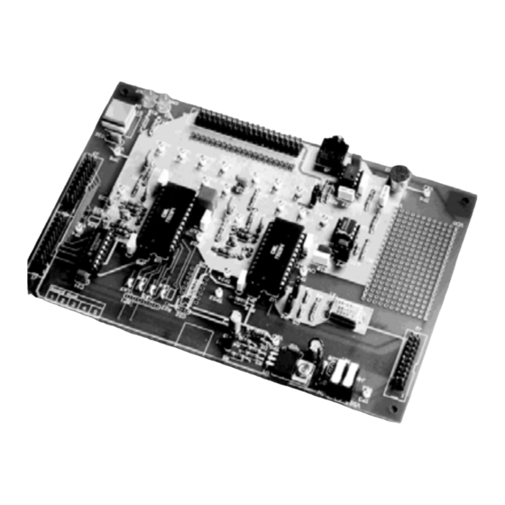
UV-Erasable PIC µC Board
•
On-Board Microphone
•
On-Board Regulator
•
Easy Access to Test Points
1.1
Brief Description
The EV8000 Evaluation Kit comprises two boards. The signalling processor board contains an
FX828 and an FX829. The signalling processor board is powered from a single 8 - 35V dc power
supply; an on-board regulator sets 3.3V or 5.0V operation. LEDs indicate the status of the FX829
carrier detect output and the FX828 comparator output. Both of these lines are available on the
same connectors as the C-BUS. The FX828 and FX829 may be driven from a common external
clock, or from a common crystal oscillator. The supply current of either target device may be
measured by removing the appropriate jumper. A user prototyping area is provided and important
signals can be monitored by test points. There is an on-board microphone and a loudspeaker
output.
C-BUS signals can be applied at either of two connectors (J1 or J2). The other can be used to
add future C-BUS evaluation kits in parallel with the EV8000. A third connector (J3) provides a
daisy chained C-BUS to enable a second EV8000 signalling processor board to be controlled
from the same PC. The signalling processor board can also be used with a user's own µC board,
with appropriate software. Component footprints are provided in case the user requires level
shifting between the C-BUS input logic HI and the V
The µC board is fitted with a PIC µC containing the firmware to interface a PC serial port to the
signalling processor board C-BUS. The EV8000 is controlled by Windows
© 2004 CML Microsystems Plc
Evaluation Kit User
•
Socketed Discrete Components
around Target Devices
•
User's Prototyping Area
•
Loudspeaker Output
•
Single Power Supply Operation
•
TM
Windows
level of the signalling processor board.
DD
EV8000
Manual
Provisional Issue
Software Included
TM
software on the PC.
Advertisement
Table of Contents

Related Manuals for CML Microcircuits EV8000


Summary of Contents for CML Microcircuits EV8000
-
Page 1: Features
C-BUS signals can be applied at either of two connectors (J1 or J2). The other can be used to add future C-BUS evaluation kits in parallel with the EV8000. A third connector (J3) provides a daisy chained C-BUS to enable a second EV8000 signalling processor board to be controlled from the same PC. -
Page 2: Table Of Contents
Evaluation Kit User Manual for FX828 and FX829 EV8000 CONTENTS Section Page Features ....................1 Brief Description ................1 Preliminary Information ..............4 1.2.1 Laboratory Equipment............... 4 1.2.2 Handling Precautions ..............4 Quick Start ................... 5 1.3.1 Setting-Up ................... 5 1.3.2... - Page 3 Evaluation Kit User Manual for FX828 and FX829 EV8000 Figure 1 Block Diagram © 2004 CML Microsystems Plc UM8000/4...
-
Page 4: Preliminary Information
Evaluation Kit User Manual for FX828 and FX829 EV8000 Preliminary Information 1.2.1 Laboratory Equipment The following laboratory equipment is needed to use this evaluation kit: 1.2.1.1 8 - 35V DC Power Supply (which can also be used to supply the PIC programming voltage, if set to 13V). -
Page 5: Quick Start
Ensure the PC software supplied is set up as detailed in Section 1.6.3.1. The EV8000 boards each have connections for a single 8 - 35V dc power supply. Only one board (as shown in Figure 1) needs to be connected as power is supplied to the other board over the 20-way flat cable. -
Page 6: Operation
Evaluation Kit User Manual for FX828 and FX829 EV8000 1.3.2 Operation This evaluation kit has no inherent functionality without the µC board and appropriate firmware and PC software. The signalling processor board may be used independently of the µC board, if the user wishes to interface to a different type of µC. -
Page 7: Signal Lists
Evaluation Kit User Manual for FX828 and FX829 EV8000 Signal Lists CONNECTOR PINOUT - SIGNALLING PROCESSOR BOARD Connector Connector Signal Signal Description Ref. Pin No. Name Type J1, J2 1, 2 V IN Power +ve power from external power supply. - Page 8 Evaluation Kit User Manual for FX828 and FX829 EV8000 CONNECTOR PINOUT - SIGNALLING PROCESSOR BOARD Connector Connector Signal Signal Description Ref. Pin No. Name Type V SS Power 0V power from external power supply. V IN Power +ve power from external power supply.
- Page 9 Evaluation Kit User Manual for FX828 and FX829 EV8000 TEST POINTS - SIGNALLING PROCESSOR BOARD Test Point Default Description Ref. Measurement 8 - 35V V IN connection. 5.0V V DD connection (3.3V or 5.0V) V SS connection. V SS connection.
- Page 10 Evaluation Kit User Manual for FX828 and FX829 EV8000 CONNECTOR PINOUT - µC BOARD Connector Connector Signal Signal Description Ref. Pin No. Name Type 1, 2 V IN Power +ve power from external power supply. 3, 4 V SS Power 0V power from external power supply.
- Page 11 Evaluation Kit User Manual for FX828 and FX829 EV8000 CONNECTOR PINOUT - µC BOARD Connector Connector Signal Signal Description Ref. Pin No. Name Type Output PC connection (linked to DTR). Output PC connection to screen. Input PC connection to keyboard.
-
Page 12: Circuit Schematics And Board Layouts
Evaluation Kit User Manual for FX828 and FX829 EV8000 Circuit Schematics and Board Layouts For clarity, circuit schematics are provided as a separate, high-resolution pdf file. 74HC4050 74F07 Figure 4 Signalling Processor Board - Layout © 2004 CML Microsystems Plc... - Page 13 Evaluation Kit User Manual for FX828 and FX829 EV8000 R2_2 R3_2 R2_1 R3_1 JP5-7 xclk board mod Figure 5 µC Board - Layout © 2004 CML Microsystems Plc UM8000/4...
-
Page 14: Detailed Description
Evaluation Kit User Manual for FX828 and FX829 EV8000 Detailed Description 1.6.1 Hardware Description - Signalling Processor Board 1.6.1.1 Operating Voltage Jumper JP1 is used to select the operating voltage. Open circuit selects 5.0V operation (default) and closed circuit (link fitted) selects 3.3V operation. -
Page 15: Hardware Description - Μc Board
Evaluation Kit User Manual for FX828 and FX829 EV8000 Hardware Description - µC Board 1.6.2 1.6.2.1 Operating Voltage Jumper JP1 is used to select the operating voltage. A link fitted at position 1,2 selects 3.3V operation and at position 2,3 selects 5.0V operation (default). Do not operate this board with the link on jumper JP1 removed. -
Page 16: Software Description - Signalling Processor Board
Evaluation Kit User Manual for FX828 and FX829 EV8000 1.6.3 Software Description - Signalling Processor Board 1.6.3.1 Installation The ES8000 Windows Application Software consists of a single executable file named ES8000xx.EXE, where xx refers to the version number. Copy this from its 3.5” floppy disk to the hard disk of the user’s PC. - Page 17 Ensure all of the hardware is connected correctly. Follow the ‘Starting the ES8000 Windows Application Software’ instructions described earlier. When the ES8000 Windows Application Software is executed a pop-up window asks the user to switch on the EV8000 kit. Switch on the power supply feeding the signalling processor and µC boards.
- Page 18 µC board reset switch. This pop-up disappears when the µC board reset switch (SW1) is pushed. Performs a General Reset on the current C-BUS. All EV8000 devices and ES8000 active device forms on this C-BUS will be reset.
- Page 19 Evaluation Kit User Manual for FX828 and FX829 EV8000 1.6.3.9 Menubars The main application menubar which resides at the top of the main window contains five pulldown menus. This menubar is available for use until a device form is opened. Whenever a device form is active a form menubar resides at the top of the main window.
- Page 20 Evaluation Kit User Manual for FX828 and FX829 EV8000 1.6.3.10 Adding a Device Form There are two ways to add device forms to the view. The quickest method is to click on the Add Device toolbar button which opens the Add Device pop-up window. The second way involves clicking on the Setup menu and then selecting the Add Device command.
- Page 21 Evaluation Kit User Manual for FX828 and FX829 EV8000 FX828 Note: The GP Timer edit box displays the number to be programmed into the GP Timer Register. © 2004 CML Microsystems Plc UM8000/4...
- Page 22 Evaluation Kit User Manual for FX828 and FX829 EV8000 FX829 For certain user input values, device programming data will not be generated and the write register concerned will not be updated. When this situation occurs a stop error message pop-up window will be opened to notify the user.
- Page 23 Update button. This will also acquire the settings of the read registers. The read register settings will then be displayed on the device form view. To minimise data exchange between the PC and EV8000, only modified write register settings are passed to the µC.
- Page 24 FX828 will display CTCSS and Selcall tones, depending on the state of the Tone Decoder Mode bit in the Signalling Set-up write register. For the FX828, both sets of tones are stored in memory but only one set is sent to the EV8000 Evaluation Kit, depending on the Tone Decode mode setting.
- Page 25 Evaluation Kit User Manual for FX828 and FX829 EV8000 1.6.3.19 Automatic Disabling of Input Controls This software feature shows the user which areas of the device form require user input and also prevents the user selecting incorrect modes of operation.
- Page 26 Evaluation Kit User Manual for FX828 and FX829 EV8000 The user can read or write to either near or far C-BUS by clicking on the respective C-BUS radio buttons (CBUS or CBUS2). The General Reset button within this window will allow the user to reset devices controlled by the selected C-BUS.
- Page 27 Evaluation Kit User Manual for FX828 and FX829 EV8000 1.6.3.22 FFSK Rx Message Select FFSKRX and AMP1 by clicking on their respective checkboxes in the Control 1 write register and enable the required synchronisation bit in the Control 3 / IRQ Enable write register. If RX SYNC WORD PRIME is selected, enter a 2-byte RX SYNC word in hex, before clicking on the Update button.
- Page 28 Evaluation Kit User Manual for FX828 and FX829 EV8000 Warning: Prolonged window resizing or similar background activities may cause application warnings or even fatal errors whilst receiving continuous FFSK messages with small inter-message delays. 1.6.3.23 FFSK Tx Message Select FFSKTX, TXIDLEM and TXDATAM by clicking on their respective checkboxes and then click on the Update button.
- Page 29 To allow the user to perform FX829 Bit Error Rate Testing (BERT) the EF8000 firmware contains a BERT routine, configured by the ES8000 Windows Application software. This facility requires two EV8000 signalling processor boards (near and far) and user input to both near and far FX829 device forms before BERT can commence.
-
Page 30: Software Description - Μc Board
Evaluation Kit User Manual for FX828 and FX829 EV8000 Two control buttons allow the user to start and stop the function which in turn generate either ‘running’ or ‘idle’ status messages. The Tester should be started before the user clicks on the Start button to ensure bit synchronisation is achieved. -
Page 31: Known Bugs In The Es8000 (V 1.0) Software
Evaluation Kit User Manual for FX828 and FX829 EV8000 Notes: Assembler output files must be in the Intel hex format (.HEX) in order to be usable by this programming software. The PIC µC supplied has a Configuration Word which is preset to 3FB9H if it is a PIC 16C74JW or 16LC74JW, or to 3FB1H if it is a PIC 16C74AJW or 16LC74AJW. -
Page 32: Troubleshooting Guide For The Es8000 (V 1.0) Software
Answer: This may occur due to an unconnected serial cable or EV8000 PSU problem. The ES8000 Windows Application Software will not function correctly after a ‘Cannot Write Port’ error message has occurred. Shutdown the ES8000 and turn off the power supply feeding the signalling processor and µC boards. -
Page 33: Performance Specification
Evaluation Kit User Manual for FX828 and FX829 EV8000 Performance Specification 1.7.1 Electrical Performance Absolute Maximum Ratings Exceeding these maximum ratings can result in damage to the Evaluation Kit. Min. Max. Units Supply (V -0.3 40.0 Supply (V -0.3 Voltage on any connector pin to V , except J3 -0.3... - Page 34 Evaluation Kit User Manual for FX828 and FX829 EV8000 Operating Characteristics For the following conditions unless otherwise specified: Evaluation Devices Xtal Frequency = 4.032MHz, µC Xtal Frequency = 4.0MHz, = 3.3V or 5.0V, Tamb = +25°C. Notes Min. Typ. Max.
- Page 35 Evaluation Kit User Manual for FX828 and FX829 EV8000 CML does not assume any responsibility for the use of any circuitry described. No IPR or circuit patent licences are implied. CML reserves the right at any time without notice to change the said circuitry and any part of this product specification.
Need help?
Do you have a question about the EV8000 and is the answer not in the manual?
Questions and answers