Table of Contents
Advertisement
Quick Links
UM9941A/1
April 2020
Features
Demonstration of SDR wireless data modem supporting multiple
bit rates and modulation schemes
Direct Conversion Receiver (CMX994E) and Cartesian Feedback
Loop Transmitter (CMX998)
1W Transmitter Operation
Designed to meet EN 302 561 / EN 300 113
1
Brief Description
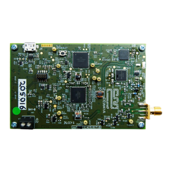
The DE9941A i s a small demonstration platform for the CMX994E Di rect Conversion Receiver, the CMX998 Ca rtesian Loop
Tra ns mitter a nd the CMX7364 Mul ti -mode Hi gh Performa nce Wi rel es s Da ta Modem. The s ma l l form fa ctor of the
demonstration/evaluation platform is possible due to the compact nature of the CML IC s oluti ons . The DE9941A ca n be
us ed to demonstrate Tx a nd Rx performance with multi-level QAM, FSK a nd GMSK type modul a ti on. Together wi th the
on-board ARM host controller, a full tra nsceiver ca n be demons tra ted us i ng a Functi on Ima ge a nd control s cri pts .
The DE9941A provi des a Fractional-N PLL a nd VCO to provi de l ocal oscillator signa l s for the CMX994E a nd CMX998. The
on-board ARM mi crocontroller, together with the control scripts, gives the user the a bility to program the RF s ynthesi s er
to the correct operating frequencies. The design also i ncludes a 1W power a mplifier, ha rmoni c fi l ter a nd Tx/Rx s wi tch.
The RF performance is designed to be compliant wi th EN 302 561 / EN 300 113 a nd a l l the ci rcui ts a re provi ded wi th
power-down ca pa bi l i ty to a l l ow s ta ndby functi on a l i ty.
The des i gn i s a i med to be l ow cos t, wi th a mi ni mum number of component types /va l ues .
2020 CML Microsystems Plc
Advanced SDR Demonstrator
USER MANUAL
Provides a demonstration platform for the
CMX7364 Multi-mode High Performance Wireless
Data Modem
On-board PLL and VCO for 350 to 400 MHz
Operation
On-board STM32 ARM microcontroller and script
handler + USB interface
Small size – 87mm x 55mm
DE9941A
User Manual
Advance Information
16 April 2020
Advertisement
Table of Contents

Related Manuals for CML Microcircuits DE9941A


Summary of Contents for CML Microcircuits DE9941A
-
Page 1: Brief Description
ARM host controller, a full tra nsceiver ca n be demons tra ted us i ng a Functi on Ima ge a nd control s cri pts . The DE9941A provi des a Fractional-N PLL a nd VCO to provi de l ocal oscillator signa l s for the CMX994E a nd CMX998. The on-board ARM mi crocontroller, together with the control scripts, gives the user the a bility to program the RF s ynthesi s er to the correct operating frequencies. -
Page 2: Table Of Contents
Advanced SDR Demonstrator DE9941A CONTENTS Secti on Pa ge Brief Description ................................. 1 Block Diagram ..................................4 Preliminary Information ..............................5 Labora tory Equipment................................. 5 3.1.1 Power Suppl y..................................5 Ha ndling Preca utions ................................5 3.2.2 Contents - Unpa cking ................................5 Approvals..................................... - Page 3 Fi gure Pa ge Fi gure 1 Block Diagra m ..................................4 Fi gure 2 Typi cal Evalua tion Connections fo r DE9941A.......................... 7 Fi gure 3 PCB La yout: top..................................10 Fi gure 4 PCB La yout: bottom ................................10 Fi gure 5 Function Image Load................................
-
Page 4: Block Diagram
Advanced SDR Demonstrator DE9941A Block Diagram Regulator +3V3D Power Regulator +3V3A Interface Connector Regulator +3V3_VCO Coax Connector Interface Regulator +3V3A_RX Regulator +3V3A_TX Tx/Rx Rx_EN Antenna MAIN CMX994E GPIO ADCs AUXADC/ (RF5110G) RAMDAC STM32 MAIN CMX998 C-BUS DACs THRU C-BUS External LO... -
Page 5: Preliminary Information
The DE9941A i s designed to be used with the ES9941A s oftwa re pa cka ge runni ng on a PC whi ch provi des control l er functi onality vi a the USB interface. This s oftware a llows scripts to be us ed to control the CMX7364. Al l RF ci rcui ts a re control led vi a the CMX7364 C-BUS i nterface. -
Page 6: Quick Start
Thi s Quick Start configuration a ssumes that the user has installed the ES9941A Wi ndows GUI software which provides the i nterface between DE9941A and a controlling PC. The script l anguage used i s the same as the PE0003. The PE0003 Scri pt La nguage Reference document i s available from the Des i gn Res ources a rea of the PE0003 product pa ge on the CML webs i te. -
Page 7: Es9941A Software And Driver Installation
ES9941A Software and Driver Installation When connecti ng the DE9941A for the fi rs t ti me the Wi ndows 10 dri ver for the STM mi crocontrol l er s houl d be a utomatically i nstalled. If any problems are experienced the STM32 Vi rtual Com Port dri ver ca n be downloaded from the STM webs ite. -
Page 8: Configuration
FI-4.x beca us e thi s ful l y uti l i ti es the Tx functi ona l i ty due to QAM bei ng a non-cons ta nt envel ope modul a ti on. The fol l owi ng procedures a l l ow the us er to qui ckl y s et up the DE9941A for Rx or Tx opera ti on. -
Page 9: Signal Lists
Advanced SDR Demonstrator DE9941A Signal Lists Table 1 Connector List CONNECTOR PINOUT Connector Connector Signal Signal Description Ref. Pin No. Name Type ANTENNA Tx Output or Rx Input 4.5V Power s uppl y i nput GNDA Power s uppl y ground... -
Page 10: Circuit Schematics And Board Layouts
Circuit Schematics and Board Layouts The DE9941A ci rcuit s chematic is a vailable as s eparate high-resolution fi l es , whi ch ca n be downl oa ded from the CML webs i te. The l a yout on ea ch s i de of the pcb i s s hown i n Fi gure 3 a nd Fi gure 4 bel ow. -
Page 11: Detailed Description
Power Amplifier The DE9941A i ncludes a 1W Power Amplifier U2 (RF5110G) configured for 350 to 400 MHz opera ti on a nd i s ca pa bl e of produci ng ~+25dBm (mea n) output power wi th 16-QAM modul a ti on. -
Page 12: Receiver
Application Information See s ecti on 4.1 for boa rd s etup deta i l s a nd s ecti on 4.2 for opera ti ng the DE9941A a s a tra ns mi tter or recei ver. 7.3.1... -
Page 13: Function Image Load
Scri pts ca n be executed us i ng the “Scri pt Ha ndl er” ta b - brows e to the rel eva nt s cri pts a nd then pres s Run. The fol l owi ng s cri pts a re a va i l a bl e to s upport the DE9941A: ... - Page 14 4, 16 a nd 64. The s cript includes a channel ta ble which configures the LMX2571 over the enti re opera ti ng ra nge of 350.05MHz to 399.55MHz. The cha nnel ta bl e i s s hown i n Ta bl e 3. Table 3 DE9941A Channel Table Frequency (MHz) Channel No 351.25...
- Page 15 Advanced SDR Demonstrator DE9941A Figure 6 Setup Script Channel No Selection Figure 7 Setup Script User Prompt to Ensure Rx Input is OFF to Allow Rx DC Calibration 2020 CML Microsystems Plc UM9941A/1...
- Page 16 Advanced SDR Demonstrator DE9941A Figure 8 Setup Script User Prompt to Check Rx Performance Figure 9 Setup Script User Prompt to Check Tx Null Condition 2020 CML Microsystems Plc UM9941A/1...
- Page 17 Advanced SDR Demonstrator DE9941A Figure 10 Setup Script Log Screen after Script has completed DE9941A_QAM_RX and DE9941A_QAM_TX At the top of the scri pts the user ca n s elect whether to test with ra w or coded data (0 = ra w/non-coded a nd 1 = coded) a nd how ma ny burs ts to do the tes t over.
- Page 18 Advanced SDR Demonstrator DE9941A Figure 11 Rx Script User Prompt to Enable AGC Figure 12 Tx Script User Prompt to Select Modulation Type to Send (4, 16, 32 or 64) 2020 CML Microsystems Plc UM9941A/1...
- Page 19 Advanced SDR Demonstrator DE9941A Figure 13 Rx Script Log Screen Following Successful Reception Figure 14 Tx Script Log Screen Following Successful Transmission 2020 CML Microsystems Plc UM9941A/1...
-
Page 20: Typi Cal Recei Ver Resul Ts With Cmx7364 Fi-4
Advanced SDR Demonstrator DE9941A Figure 15 Typical ber_results.txt file Output From the Rx 7.3.4 Typical Receiver Results with CMX7364 FI-4 The Receiver Response Equaliser wi thin the CMX7364 ha s been used in s ingle mode to crea te a cha nnel fi l ter tha t ha s compensation for the ADCs and also the channel filtering within the Rx chain. - Page 21 -93dBm Sensitivity results for the DE9941A for 4-QAM, 16-QAM a nd 64-QAM a re s hown i n Figure 16; the res ul ts were ta ken a t 366.5MHz. It ca n be s een tha t there i s s i gni fi ca nt ma rgi n on the EN 300 113 l i mi ts a bove.
- Page 22 Advanced SDR Demonstrator DE9941A Fi gure 17 s hows the 4-QAM s ensitivity performance at the top, middle a nd bottom of the frequency ra nge; channel 16, 8 a nd 1 res pecti vel y. Figure 17 Rx Sensitivity at Different Frequencies with 4-QAM, 18 ksymbols/s Adjacent Channel Rejection The a djacent channel rejection was measured with the wanted signal at -102dBm (i.e.
- Page 23 Advanced SDR Demonstrator DE9941A The res ul ts i n Ta bl e 6 s how tha t thi s l i mi t ca n be met wi th 16-QAM modul a ti on, wi th ~4dB ma rgi n.
- Page 24 Advanced SDR Demonstrator DE9941A Figure 18 4-QAM, 16-QAM and 64-QAM Co-Channel Performance Intermodulation Intermodulation was measured a gainst EN 300 113, whi ch specifies that the wanted tone is 3dB a bove the limit s pecifi ed i n Ta ble 4 a nd the s pacing between the unwanted tones is 50kHz. The fi rst unwanted tone wa s a t +/-50kHz offs et from wa nted and was un-modulated.
-
Page 25: Typi Cal Tra Nsmi T Performance Wi Th Cmx7364 Fi -4
Advanced SDR Demonstrator DE9941A Table 10 4-QAM Rx Spurious Response and Blocking Performance Interferer Offset of Level Comment Interferer (Hz) (dBm) Modul a ted -33.5 Modul a ted 100k -33.5 Modul a ted 125k -33.5 Modul a ted 150k Modul a ted... - Page 26 Advanced SDR Demonstrator DE9941A 16-QAM ACP The pl ot i n Figure 19 wa s taken at 350.05MHz, Fi gure 20 i s a t 366.5MHz a nd Figure 21 i s at 399.55MHz wi th a ba ud ra te of 18 ks ymbols/s.
- Page 27 Advanced SDR Demonstrator DE9941A Figure 21 16-QAM, 18 ks/s, ACP Performance at 399.55MHz Figure 22 16-QAM, 9.6 ks/s, ACP Performance at 366.5MHz Figure 23 16-QAM, 40 ks/s, ACP Performance at 366.5MHz 2020 CML Microsystems Plc UM9941A/1...
- Page 28 16-QAM Constellation and EVM In Fi gure 24 to Fi gure 26 there are plots of the DE9941A Tx output a t 366.5MHz a t di fferent ba ud ra tes , s howi ng the res ul ta nt cons tel l a ti on a nd EVM.
- Page 29 Advanced SDR Demonstrator DE9941A Figure 27 Wideband Plots of Tx at 350.05MHz Figure 28 Wideband Plots of Tx at 366.5MHz Figure 29 Wideband Plots of Tx at 399.55MHz 2020 CML Microsystems Plc UM9941A/1...
- Page 30 Advanced SDR Demonstrator DE9941A Power and Modulation Ramping Pl ots in Figure 30 a nd Figure 31 s how the ra mp-up a nd ra mp-down profiles using QAM a nd the plots in Figure 31 to Figure 33 s how the s pectra l puri ty us i ng ma x hol d on the tra ces for 100 burs ts tra ns mi tted .
- Page 31 Advanced SDR Demonstrator DE9941A Figure 33 Tx Spectral Purity in Transient Mode, 10MHz Span (QAM) 2020 CML Microsystems Plc UM9941A/1...
-
Page 32: Troubleshooting
Troubleshooting The DE9941A i s a complex RF and baseband system. If i ncorrectly programmed or modified, res ul ts wi l l be a t va ri a nce from da tasheet performance. Pl ease s tudy the CMX7364, CMX998 a nd CMX994E da ta sheets, along with the manuals and the a ssociated s chematics and layout drawings for these a nd the DE9941A PCB ca reful l y when troubl es hooti ng. -
Page 33: Performance Specification
Advanced SDR Demonstrator DE9941A Performance Specification Electrical Performance 8.1.1 Absolute Maximum Ratings Exceedi ng thes e ma xi mum ra ti ngs ca n res ul t i n da ma g e to the Eva l ua ti on Ki t. -
Page 34: Opera Ting Cha Ra Cteris Ti Cs
Advanced SDR Demonstrator DE9941A 8.1.3 Operating Characteristics For the fol l owi ng condi ti ons unl es s otherwi s e s peci fi ed: Xta l Frequency = 38.4MHz, Bi t Ra te = 18ksymbols/s, Noi s e Bandwidth = 16kHz, V = 4.5V, T... - Page 35 Advanced SDR Demonstrator DE9941A CML does not assume any responsibility for the use of any circuitry described. No IP R or circuit patent licences are implied. CML reserves the right at any time without notice to change the said circuitry and any part of this product specification. Evaluation kits and demonstration boards are supplied for the sole purpose of demonstrati ng the operation of CML products and are supplied without warranty.
- Page 36 Mouser Electronics Authorized Distributor Click to View Pricing, Inventory, Delivery & Lifecycle Information: CML Microcircuits DE9941A-375...
Need help?
Do you have a question about the DE9941A and is the answer not in the manual?
Questions and answers