ASROCK H55M LE - V 1.0 - 01-2010 User Manual
Hide thumbs
Also See for H55M LE - V 1.0 - 01-2010:
- Brochure (6 pages) ,
- Installation manual (181 pages)

Related Manuals for ASROCK H55M LE - V 1.0 - 01-2010


Summary of Contents for ASROCK H55M LE - V 1.0 - 01-2010
- Page 1 H55M-LE User Manual Version 1.0 Published January 2010 Copyright©2010 ASRock INC. All rights reserved. 1 1 1 1 1...
- Page 2 (including damages for loss of profits, loss of business, loss of data, interruption of business and the like), even if ASRock has been advised of the possibility of such damages arising from any defect or error in the manual or product.
-
Page 3: Table Of Contents
2.10 SATAII Hard Disk Setup Guide ........26 2.11 Serial ATA (SATA) / Serial ATAII (SATAII) Hard Disks Installation ..............27 2.12 Hot Plug Function for SATA / SATAII HDDs ....27 2.13 SATA / SATAII HDD Hot Plug Feature and Operation Guide ................28 2.14 Driver Installation Guide .......... - Page 4 3.4.5 PCIPnP Configuration ........... 45 3.4.6 Super IO Configuration ........46 3.4.7 USB Configuration ..........47 3.5 Hardware Health Event Monitoring Screen ....48 3.6 Boot Screen ..............49 3.6.1 Boot Settings Configuration ........49 3.7 Security Screen ............50 3.8 Exit Screen ..............
-
Page 5: Introduction
ASRock’s commitment to quality and endurance. In this manual, chapter 1 and 2 contain introduction of the motherboard and step-by-step guide to the hardware installation. Chapter 3 and 4 contain the configuration guide to BIOS setup and information of the Support CD. -
Page 6: Specifications
Specifications Specifications Specifications Specifications Specifications - Micro ATX Form Factor: 9.6-in x 8.0-in, 24.4 cm x 20.3 cm Platform - Solid Capacitor for CPU power - Supports Intel Core i7 / i5 / i3 and Pentium G6950 ® ® Processors in LGA1156 Package... - Page 7 - 1 x VGA/D-Sub Port - 1 x VGA/DVI-D Port - 6 x Ready-to-Use USB 2.0 Ports - 1 x RJ-45 LAN Port with LED (ACT/LINK LED and SPEED LED) - HD Audio Jack: Side Speaker/Rear Speaker/Central/Bass/ Line in/Front Speaker/Microphone (see CAUTION 8) - 4 x SATAII 3.0Gb/s connectors, support NCQ, AHCI and “Hot...
- Page 8 Overclocking may affect your system stability, or even cause damage to the components and devices of your system. It should be done at your own risk and expense. We are not responsible for possible damage caused by overclocking.
- Page 9 OS with 64-bit CPU, there is no such limitation. ® For those CPU that only support up to DDR3 1333, the XMP DDR3 1600 is supported through overclocking. The maximum shared memory size is defined by the chipset vendor and is subject to change.
- Page 10 USB flash drive or hard drive must use FAT32/16/12 file system. 14. The software name itself – OC DNA literally tells you what it is capable of. OC DNA, an exclusive utility developed by ASRock, provides a conve- nient way for the user to record the OC settings and share with others.
-
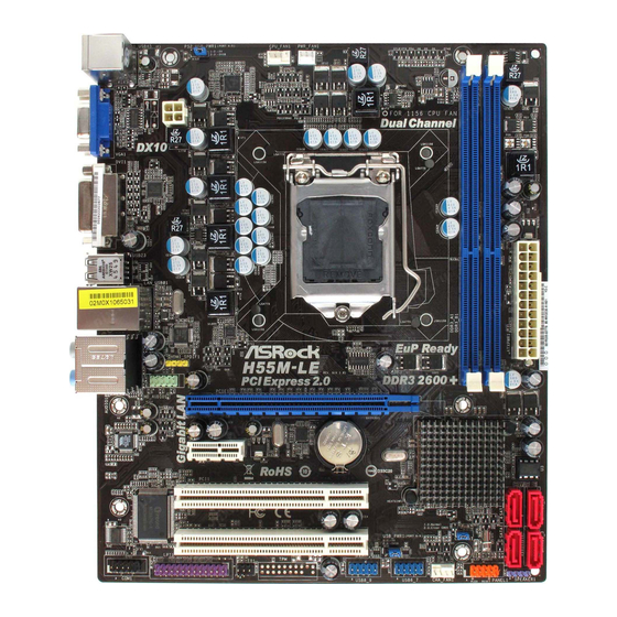
Page 11: Motherboard Layout
COM Port Header (COM1) 16Mb SPI Flash PCI Slots (PCI1-2) Secondary SATAII Connector (SATAII_2, Red) PCI Express 2.0 x1 Slot (PCIE2, White) Primary SATAII Connector (SATAII_1, Red) PCI Express 2.0 x16 Slot (PCIE1, Blue) Third SATAII Connector (SATAII_3, Red) Front Panel Audio Header... -
Page 12: I/O Panel
Line In (Light Blue) PS/2 Keyboard Port (Purple) ** 7 Front Speaker (Lime) * There are two LED next to the LAN port. Please refer to the table below for the LAN port LED indications. LAN Port LED Indications ACT/LINK... - Page 13 To enable Multi-Streaming function, you need to connect a front panel audio cable to the front panel audio header. After restarting your computer, you will find “VIA HD Audio Deck” tool on your system. Please follow below instructions according to the OS you install.
-
Page 14: Installation
Chapter 2: Installation Chapter 2: Installation This is a Micro ATX form factor (9.6" x 8.0", 24.4 x 20.3 cm) motherboard. Before you install the motherboard, study the configuration of your chassis to ensure that the motherboard fits into it. -
Page 15: Cpu Installation
Before you insert the 1156-Pin CPU into the socket, please check if the CPU surface is unclean or if there is any bent pin on the socket. Do not force to insert the CPU into the socket if above situation is found. - Page 16 1156-Pin CPU For proper inserting, please ensure to match the two orientation key notches of the CPU with the two alignment keys of the socket. Step 3-3. Carefully place the CPU into the socket by using a purely vertical motion.
-
Page 17: Installation Of Heatsink And Cpu Fan
CPU and the heatsink to improve heat dissipation. Ensure that the CPU and the heatsink are securely fastened and in good contact with each other. Then connect the CPU fan to the CPU_FAN connector (CPU_FAN1, see page 11, No. -
Page 18: Installation Of Memory Modules (Dimm)
DIMMs or the system components. Step 1. Unlock a DIMM slot by pressing the retaining clips outward. Step 2. Align a DIMM on the slot such that the notch on the DIMM matches the break on the slot. notch break... -
Page 19: Expansion Slots (Pci And Pci Express Slots)
PCIE1 (PCIE x16 slot; Blue) is used for PCI Express x16 lane width graphics cards. PCIE2 (PCIE x1 slot; White) is used for PCI Express cards with x1 lane width cards, such as Gigabit LAN card, SATA2 card, etc. Installing an expansion card... -
Page 20: Jumpers Setup
After waiting for 15 seconds, use a jumper cap to short pin2 and pin3 on CLRCMOS1 for 5 seconds. However, please do not clear the CMOS right after you update the BIOS. -
Page 21: Onboard Headers And Connectors
2.8 Onboard Headers and Connectors Onboard headers and connectors are NOT jumpers. Do NOT place jumper caps over these headers and connectors. Placing jumper caps over the headers and connectors will cause permanent damage of the motherboard! Serial ATAII Connectors... - Page 22 HDA to function correctly. Please follow the instruction in our manual and chassis manual to install your system. 2. If you use AC’97 audio panel, please install it to the front panel audio header as below: A.
- Page 23 Though this motherboard provides 4-Pin CPU fan (Quiet Fan) support, the 3-Pin CPU fan still can work successfully even without the fan speed control function. If you plan to connect the 3-Pin CPU fan to the CPU fan connector on this motherboard, please connect it to Pin 1-3.
- Page 24 HDMI_SPDIF Header HDMI_SPDIF header, providing SPDIF audio output to HDMI VGA (3-pin HDMI_SPDIF1) card, allows the system to (see p.11 No. 29) SPDIFOUT connect HDMI Digital TV/ projector/LCD devices. Please connect the HDMI_SPDIF connector of HDMI VGA card to this header.
-
Page 25: Hdmi_Spdif Header Connection Guide
HDMI (High-Definition Multi-media Interface) is an all-digital audio/video specification, which provides an interface between any compatible digital audio/ video source, such as a set-top box, DVD player, A/V receiver and a compatible digital audio or video monitor, such as a digital television (DTV). A complete HDMI system requires a HDMI VGA card and a HDMI ready motherboard with a HDMI_SPDIF header. -
Page 26: Sataii Hard Disk Setup Guide
Before installing SATAII hard disk to your computer, please carefully read below SATAII hard disk setup guide. Some default setting of SATAII hard disks may not be at SATAII mode, which operate with the best performance. In order to enable SATAII function, please follow the below instruction with different vendors to correctly adjust your SATAII hard disk to SATAII mode in advance;... -
Page 27: Installation
STEP 2: Connect the SATA power cable to the SATA / SATAII hard disk. STEP 3: Connect one end of the SATA data cable to the motherboard’s SATAII connector. STEP 4: Connect the other end of the SATA data cable to the SATA / SATAII hard disk. 2.12 Hot Plug F 2.12 Hot Plug F... -
Page 28: Guide
SATA / SATAII driver is available on our support website: www.asrock.com 4. Make sure to use the SATA power cable & data cable, which are from our motherboard package. 5. Please follow below instructions step by step to reduce the risk of HDD crash... - Page 29 Please do follow below instruction sequence to process the Hot Unplug, improper procedure will cause the SATA / SATAII HDD damage and data loss. Step 1 Unplug SATA data cable from SATA / SATAII HDD side. Unplug SATA 15-pin power cable connector (Black) from SATA / SATAII HDD side. Step 2...
-
Page 30: Driver Installation Guide
2.14 Driver Installation Guide To install the drivers to your system, please insert the support CD to your optical drive first. Then, the drivers compatible to your system can be auto-detected and listed on the support CD driver page. Please follow the order from up to bottom side to install those required drivers. -
Page 31: Untied Overclocking Technology
Untied Overclocking function, please enter “Overclock Mode” option of BIOS setup to set the selection from [Auto] to [Manual]. Therefore, CPU FSB is untied during overclocking, but PCI / PCIE buses are in the fixed mode so that FSB can operate under a more stable overclocking environment. -
Page 32: Bios Setup Utility
The BIOS FWH chip on the motherboard stores the BIOS SETUP UTILITY. You may run the BIOS SETUP UTILITY when you start up the computer. Please press <F2> or <Del> during the Power-On-Self-Test (POST) to enter the BIOS SETUP UTILITY, otherwise, POST will continue with its test routines. -
Page 33: Navigation Keys
3 . 2 3 . 2 3 . 2 Main Screen Main Screen Main Screen When you enter the BIOS SETUP UTILITY, the Main screen will appear and display the system overview. BIOS SETUP UTILITY OC Tweaker Advanced H/W Monitor... -
Page 34: Oc Tweaker Screen
® ® Load CPU EZ OC Setting You can use this option to load CPU EZ overclocking setting. Please note that overclocing may cause damage to your CPU and motherboard. It should be done at your own risk and expense. - Page 35 Good Night LED Enable this option to turn off Power LED and Lan LED when the system is power on. The keyboard LED will also be turned off in S1, S3 and S4 state. The default value is [Disabled]. Overclock Mode Use this to select Overclock Mode.
- Page 36 Exit v02.54 (C) Copyright 1985-2005, American Megatrends, Inc. DRAM tCL Use this item to adjust the means of memory accessing. Configuration options : [Auto], [6] to [11]. DRAM tRCD This controls the number of DRAM clocks for TRCD. Configuration options: [Auto], [3] to [15].
- Page 37 IGD VID Use this to select onboard VGA VID. The default value is [Auto]. Would you like to save current setting user defaults? In this option, you are allowed to load and save three user defaults according to your own requirements.
-
Page 38: Advanced Screen
. Just launch ® this tool and save the new BIOS file to your USB flash drive, floppy disk or hard drive, then you can update your BIOS only in a few clicks without preparing an additional floppy diskette or other complicated flash utility. -
Page 39: Cpu Configuration
[Enabled] v02.54 (C) Copyright 1985-2005, American Megatrends, Inc. CPU Ratio Setting If the ratio status is unlocked, you will find this item appear to allow you changing the ratio value of this motherboard. Enhance Halt State All processors support the Halt State (C1). The C1 state is supported through the native processor instructions HLT and MWAIT and requires no hardware support from the chipset. - Page 40 Intel (R) C-STATE tech. is achieved by making the power and thermal con- trol unit part of the core logic and not part of the chipset as before. Migration of the power and thermal management flow into the processor allows us...
-
Page 41: Chipset Configuration
DVMT/FIXED Memory You are allowed to adjust the shared memory size in this item if you set DVMT Mode Select as [DVMT Mode]. Configuration options: [128MB], [256MB] and [Maximum DVMT]. The option [Maximum DVMT] only appears when you adopt the memory module with 1024MB or above. -
Page 42: Acpi Configuration
Use this item to enable or disable Ring-In signals to turn on the system from the power-soft-off mode. PCI Devices Power On Use this item to enable or disable PCI devices to turn on the system from the power-soft-off mode. PS/2 Keyboard Power On Use this item to enable or disable PS/2 keyboard to turn on the system from the power-soft-off mode. -
Page 43: Storage Configuration
RTC Alarm Power On Use this item to enable or disable RTC (Real Time Clock) to power on the system. ACPI HPET Table Use this item to enable or disable ACPI HPET Table. The default value is [Disabled]. Please set this option to [Enabled] if you plan to use this... - Page 44 [ARMD]: This is used for IDE ARMD (ATAPI Removable Media Device), such as MO. LBA/Large Mode Use this item to select the LBA/Large mode for a hard disk > 512 MB under DOS and Windows; for Netware and UNIX user, select [Disabled] to disable the LBA/Large mode.
-
Page 45: Pcipnp Configuration
Reporting Technology) feature. Configuration options: [Disabled], [Auto], [Enabled]. 32-Bit Data Transfer Use this item to enable 32-bit access to maximize the IDE hard disk data transfer rate. 3 . 4 . 5 3 . 4 . 5 PCIPnP Configuration 3 . -
Page 46: Super Io Configuration
(C) Copyright 1985-2003, American Megatrends, Inc. Serial Port Address Use this item to set the address for the onboard serial port or disable it. Configuration options: [Disabled], [3F8 / IRQ4], [2F8 / IRQ3], [3E8 / IRQ4], [2E8 / IRQ3]. -
Page 47: Usb Configuration
[Enabled] - Enables support for legacy USB. [Auto] - Enables legacy support if USB devices are connected. [Disabled] - USB devices are not allowed to use under legacy OS and BIOS setup when [Disabled] is selected. If you have USB compatibility issue, it is recommended to select [Disabled] to enter OS. -
Page 48: Hardware Health Event Monitoring Screen
3 . 5 Hardware Health Event Monitoring Screen In this section, it allows you to monitor the status of the hardware on your system, including the parameters of the CPU temperature, motherboard temperature, CPU fan speed, chassis fan speed, and the critical voltage. -
Page 49: Boot Screen
Boot Screen Boot Screen 3 . 6 3 . 6 Boot Screen In this section, it will display the available devices on your system for you to configure the boot settings and the boot priority. BIOS SETUP UTILITY Main OC Tweaker... -
Page 50: Security Screen
Security Screen 3 . 7 3 . 7 Security Screen In this section, you may set or change the supervisor/user password for the system. For the user password, you may also clear it. BIOS SETUP UTILITY Main OC Tweaker Advanced... -
Page 51: Exit Screen
When you select this option, it will pop-out the following message, “Discard changes?” Select [OK] to discard all changes. Load BIOS Defaults Load BIOS default values for all the setup questions. F9 key can be used for this operation. Load Performance Setup Default (IDE/SATA) This performance setup default may not be compatible with all system configurations. -
Page 52: Install Operating System
4 . 2 . 4 4 . 2 . 4 C o n t a c t I n f o r m a t i o n C o n t a c t I n f o r m a t i o n...
Need help?
Do you have a question about the H55M LE - V 1.0 - 01-2010 and is the answer not in the manual?
Questions and answers