
Related Manuals for ASROCK H55M


Summary of Contents for ASROCK H55M
- Page 1 H55M User Manual Version 1.1 Published March 2010 Copyright©2010 ASRock INC. All rights reserved. 1 1 1 1 1...
- Page 2 ASRock. ASRock assumes no responsibility for any errors or omissions that may appear in this guide. With respect to the contents of this guide, ASRock does not provide warranty of any kind, either expressed or implied, including but not limited to the implied warranties or condi- tions of merchantability or fi...
-
Page 3: Table Of Contents
Contents Contents Contents Contents Contents 1 Introduction 1 Introduction ........... 1 Introduction ...................... 5 5 5 5 5 ........... 1 Introduction 1 Introduction ........... 1.1 Package Contents ............5 1.2 Specifications ..............6 1.3 Two CrossFireX Graphics Card Support List .... 11 1.4 Motherboard Layout ............ - Page 4 3 BIOS S 3 BIOS SETUP UTILITY 3 BIOS S ETUP UTILITY ETUP UTILITY ETUP UTILITY .................................... 37 3 BIOS S 3 BIOS S ETUP UTILITY ........... Introduction Introduction Introduction Introduction Introduction ..............................................37 3.1.1 BIOS Menu Bar ............
-
Page 5: Introduction
In case any modifications of this manual occur, the updated version will be available on ASRock website without further notice. You may find the latest VGA cards and CPU support lists on ASRock website as well. ASRock website http://www.asrock.com If you require technical support related to this motherboard, please visit our website for specific information about the model you are using. -
Page 6: Specifications
Specifications Specifications Specifications Specifications Specifications Platform - Micro ATX Form Factor: 9.6-in x 8.8-in, 24.4 cm x 22.4 cm - Solid Capacitor for CPU power ® ® - Supports Intel Core i7 / i5 / i3 and Pentium G6950 Processors in LGA1156 Package - 4 + 1 Power Phase Design - Supports Intel ®... - Page 7 Audio - 7.1 CH HD Audio (VIA ® VT1718S Audio Codec) - PCIE x1 Gigabit LAN 10/100/1000 Mb/s - Realtek RTL8111DL - Supports Wake-On-LAN Rear Panel I/O I/O Panel - 1 x PS/2 Keyboard Port - 1 x VGA/D-Sub Port - 1 x VGA/DVI-D Port - 1 x HDMI Port - 1 x Optical SPDIF Out Port...
- Page 8 - FCC, CE, WHQL - EuP Ready (EuP ready power supply is required) (see CAUTION 20) * For detailed product information, please visit our website: http://www.asrock.com WARNING Please realize that there is a certain risk involved with overclocking, including adjusting the setting in the BIOS, applying Untied Overclocking Technology, or using the third- party overclocking tools.
- Page 9 64-bit / Vista / XP 64-bit / XP SP1 or SP2. 13. It is a user-friendly ASRock overclocking tool which allows you to surveil your system by hardware monitor function and overclock your hardware devices to get the best system performance under Windows ®...
- Page 10 15. ASRock Instant Flash is a BIOS flash utility embedded in Flash ROM. This convenient BIOS update tool allows you to update system BIOS without entering operating systems first like MS-DOS or Windows ® . With this utility, you can press <F6> key during the POST or press <F2> key to BIOS setup menu to access ASRock Instant Flash.
-
Page 11: Tm Graphics Card Support List
Catalyst 9.7 Powercolor HD3870/512MB Radeon HD 3870 Catalyst 9.7 Powercolor HD4670/512MB-GDDR3 Radeon HD4670 Catalyst 9.7 * For the latest updates of the supported PCI Express VGA card list for CrossFireX Mode, please visit our website for details. ASRock website: http://www.asrock.com/support/index.htm... -
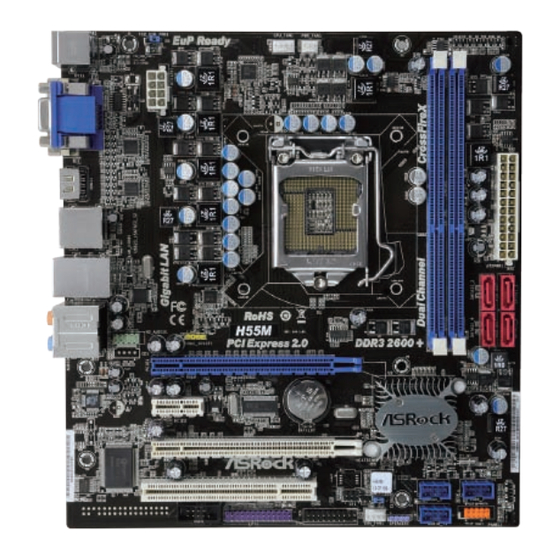
Page 12: Motherboard Layout
22.4cm (8.8 in) EuP Ready USB 2.0 PS2_USB_PWR1 T: USB4 B: USB5 CPU_FAN1 PWR_FAN1 ATX12V1 USB 2.0 Top: T: USB0 RJ-45 B: USB1 RoHS H55M HD_AUDIO1 PCI Express 2.0 DDR3 2600+ HDMI_SPDIF1 PCIE1 CMOS AUDIO CODEC Intel PCIE2 Battery PCIE3 16Mb USB8_9... -
Page 13: I/O Panel
I/O Panel I/O Panel I/O Panel I/O Panel I/O Panel USB 2.0 Ports (USB45) ** 8 Front Speaker (Lime) VGA/D-Sub Port Microphone (Pink) LAN RJ-45 Port USB 2.0 Ports (USB01) Central / Bass (Orange) Powered eSATAII/USB Connectors Rear Speaker (Black) HDMI Port Optical SPDIF Out Port VGA/DVI-D Port... - Page 14 To enable Multi-Streaming function, you need to connect a front panel audio cable to the front panel audio header. After restarting your computer, you will find “VIA HD Audio Deck” tool on your system. Please follow below instructions according to the OS you install. ®...
-
Page 15: Installation
Chapter 2: Installation Chapter 2: Installation Chapter 2: Installation Chapter 2: Installation Chapter 2: Installation This is a Micro ATX form factor (9.6" x 8.8", 24.4 x 22.4 cm) motherboard. Before you install the motherboard, study the configuration of your chassis to ensure that the motherboard fits into it. -
Page 16: Cpu Installation
2.3 CPU Installation 2.3 CPU Installation 2.3 CPU Installation 2.3 CPU Installation 2.3 CPU Installation For the installation of Intel 1156-Pin CPU, please follow the steps below. Load Plate Load Lever Socket Body Contact Array 1156-Pin Socket Overview Before you insert the 1156-Pin CPU into the socket, please check if the CPU surface is unclean or if there is any bent pin on the socket. - Page 17 Step 3. Insert the 1156-Pin CPU: Step 3-1. Hold the CPU by the edge where is marked with black line. Step 3-2. Orient the CPU with IHS (Integrated Heat Sink) up. Locate Pin1 and the two ori- entation key notches. orientation key notch alignment key Pin1...
-
Page 18: Installation Of Heatsink And Cpu Fan
Installation of CPU Fan and Heatsink Installation of CPU Fan and Heatsink Installation of CPU Fan and Heatsink Installation of CPU Fan and Heatsink Installation of CPU Fan and Heatsink This motherboard is equipped with 1156-Pin socket that supports Intel 1156-Pin CPU. Please adopt the type of heatsink and cooling fan compliant with Intel 1156-Pin CPU to dissipate heat. -
Page 19: Installation Of Memory Modules (Dimm)
2.5 Installation of Memory Modules (DIMM) 2.5 Installation of Memory Modules (DIMM) H55M motherboard provides two 240-pin DDR3 (Double Data Rate 3) DIMM slots, and supports Dual Channel Memory Technology. For dual channel configuration, you always need to install two identical (the same brand, speed, size and chip- type) memory modules in the DDR3 DIMM slots to activate Dual Channel Memory Technology. -
Page 20: Expansion Slots (Pci And Pci Express Slots)
2.6 Expansion Slots (PCI and PCI Express Slots) 2.6 Expansion Slots (PCI and PCI Express Slots) 2.6 Expansion Slots (PCI and PCI Express Slots) 2.6 Expansion Slots (PCI and PCI Express Slots) 2.6 Expansion Slots (PCI and PCI Express Slots) There are 1 PCI slot and 3 PCI Express slots on this motherboard. -
Page 21: Crossfirex
CrossFireX CrossFireX CrossFireX and Quad CrossFireX and Quad CrossFireX and Quad CrossFireX Operation Operation Operation CrossFireX CrossFireX and Quad CrossFireX and Quad CrossFireX Operation Operation Guide Guide Guide Guide Guide This motherboard supports CrossFireX and Quad CrossFireX feature. CrossFireX technology offers the most advantageous means available of combining multiple high performance Graphics Processing Units (GPU) in a single PC. - Page 22 Step 2. Connect two Radeon graphics cards by installing CrossFire Bridge on CrossFire Bridge Interconnects on the top of Radeon graphics cards. (CrossFire Bridge is provided with the graphics card you purchase, not bundled with this motherboard. Please refer to your graphics card vendor for details.) CrossFire Bridge Step 2.
- Page 23 2.7.2 Driver Installation and Setup 2.7.2 Driver Installation and Setup 2.7.2 Driver Installation and Setup 2.7.2 Driver Installation and Setup 2.7.2 Driver Installation and Setup Step 1. Power on your computer and boot into OS. Step 2. Remove the ATI driver if you have any VGA driver installed in your system.
-
Page 24: Tm Tm
Although you have selected the option “Enable CrossFire ”, the CrossFireX function may not work actually. Your computer will automatically reboot. After restarting your computer, please confirm whether the option “Enable CrossFire ” in “ATI Catalyst Control Center” is selected or not; if not, please select it again, and then you are able to enjoy the benefit of CrossFireX feature. -
Page 25: Surround Display Feature
2.8 Surround Display Feature 2.8 Surround Display Feature 2.8 Surround Display Feature 2.8 Surround Display Feature 2.8 Surround Display Feature This motherboard supports Surround Display upgrade. With the external add-on PCI Express VGA cards, you can easily enjoy the benefits of Surround Display feature. -
Page 26: Onboard Headers And Connectors
2.10 Onboard Headers and Connectors 2.10 Onboard Headers and Connectors 2.10 Onboard Headers and Connectors 2.10 Onboard Headers and Connectors 2.10 Onboard Headers and Connectors Onboard headers and connectors are NOT jumpers. Do NOT place jumper caps over these headers and connectors. Placing jumper caps over the headers and connectors will cause permanent damage of the motherboard! Serial ATAII Connectors... - Page 27 TPM Header This connector supports a Trusted Platform Module (TPM) (19-pin TPM1) system, which can securely (see p.12 No. 22) store keys, digital certificates, passwords, and data. A TPM system also helps enhance network security, protects digital identities, and ensures platform integrity.
- Page 28 System Panel Header This header accommodates PLED+ PLED- PWRBTN# several system front panel (9-pin PANEL1) functions. (see p.12 No. 16) DUMMY RESET# HDLED- HDLED+ Chassis Speaker Header Please connect the chassis speaker to this header. SPEAKER (4-pin SPEAKER 1) DUMMY DUMMY (see p.12 No.
- Page 29 ATX 12V Power Connector Please connect an ATX 12V power supply to this connector. (8-pin ATX12V1) (see p.12 No. 1) Though this motherboard provides 8-pin ATX 12V power connector, it can still work if you adopt a traditional 4-pin ATX 12V power supply. To use the 4-pin ATX power supply, please plug your power supply along with Pin 1 and Pin 5.
-
Page 30: Hdmi_Spdif Header Connection Guide
2.11 HDMI_SPDIF Header Connection Guide 2.11 HDMI_SPDIF Header Connection Guide 2.11 HDMI_SPDIF Header Connection Guide 2.11 HDMI_SPDIF Header Connection Guide 2.11 HDMI_SPDIF Header Connection Guide HDMI (High-Definition Multi-media Interface) is an all-digital audio/video specification, which provides an interface between any compatible digital audio/ video source, such as a set-top box, DVD player, A/V receiver and a compatible digital audio or video monitor, such as a digital television (DTV). -
Page 31: Sataii Hard Disk Setup Guide
2.12 SA 2.12 SA 2.12 SAT T T T T AII Hard Disk Setup Guide AII Hard Disk Setup Guide AII Hard Disk Setup Guide AII Hard Disk Setup Guide 2.12 SA 2.12 SA AII Hard Disk Setup Guide Before installing SATAII hard disk to your computer, please carefully read below SATAII hard disk setup guide. -
Page 32: Installation
2.13 2.13 Serial A 2.13 Serial A Serial A Serial AT T T T T A (SA A (SA A (SAT T T T T A) / Serial A A (SA A) / Serial A A) / Serial AT T T T T AII (SA A) / Serial A AII (SA AII (SAT T T T T AII) Hard Disks... -
Page 33: Guide
SATA / SATAII Hot Plug support information of our motherboard is indicated in the product spec on our website: www.asrock.com 2. Make sure your SATA / SATAII HDD can support Hot Plug function from your dealer or HDD user manual. - Page 34 How to Hot Plug a SATA / SATAII HDD: Points of attention, before you process the Hot Plug: Please do follow below instruction sequence to process the Hot Plug, improper procedure will cause the SATA / SATAII HDD damage and data loss. Step 1 Step 2 Please connect SATA power cable 1x4-pin end...
-
Page 35: Driver Installation Guide
2.16 2.16 2.16 Driver Installation Guide Driver Installation Guide Driver Installation Guide Driver Installation Guide 2.16 2.16 Driver Installation Guide To install the drivers to your system, please insert the support CD to your optical drive first. Then, the drivers compatible to your system can be auto-detected and listed on the support CD driver page. -
Page 36: Untied Overclocking Technology
Using SATA / SATAII HDDs without NCQ function STEP 1: Set up BIOS. A. Enter BIOS SETUP UTILITY Advanced screen Storage Configuration. B. Set the option “SATA Operation Mode” to [IDE]. STEP 2: Install Windows ® 7 / 7 64-bit / Vista / Vista 64-bit OS on your system. -
Page 37: Bios Setup Utility
Chapter 3: BIOS SETUP UTILITY Chapter 3: BIOS SETUP UTILITY Chapter 3: BIOS SETUP UTILITY Chapter 3: BIOS SETUP UTILITY Chapter 3: BIOS SETUP UTILITY 3 . 1 3 . 1 3 . 1 Introduction Introduction Introduction 3 . 1 3 . -
Page 38: Navigation Keys
System Time [ :00:09] select a field. System Date [Mon 11/09/2009] Use [+] or [-] to BIOS Version : H55M P1.00 configure system Time. Processor Type : Intel (R) Core (TM) CPU 870 @ 2.93GHz (64bit) Processor Speed : 2933MHz... -
Page 39: Oc Tweaker Screen
3.3 OC T OC T OC T OC Tweak weak weak weaker Screen er Screen er Screen er Screen OC T weak er Screen In the OC Tweaker screen, you can set up overclocking features. BIOS SETUP UTILITY Main OC Tweaker Advanced H/W Monitor Boot... - Page 40 If you select [I.O.T.] (Intelligent Overclocking Technology), the system will automatically enable the overclocking function when your CPU is heavy loaded. BCLK Frequency (MHz) Use this option to adjust BCLK (Internal Base Clock) frequency. PCIE Frequency (MHz) Use this option to adjust PCIE frequency. Boot Failure Guard Enable or disable the feature of Boot Failure Guard.
- Page 41 DRAM tRAS This controls the number of DRAM clocks for TRAS. Configuration options: [Auto], [9] to [31]. DRAM tRFC This controls the number of DRAM clocks for TRFC. Configuration options: [Auto], [15] to [255]. DRAM tWR This controls the number of DRAM clocks for TWR. Configuration options: [Auto], [3] to [15].
- Page 42 ASRock VDrop Control Use this to enable or disable ASRock VDrop control. Configuration options: [With VDrop] and [Without VDrop]. The default value is [With VDrop]. CPU Voltage Use this to select CPU Voltage. Configuration options: [Auto], [Manual] and [Overdrive Offset]. The default value is [Auto].
-
Page 43: Advanced Screen
Setting wrong values in this section may cause the system to malfunction. ASRock Instant Flash ASRock Instant Flash is a BIOS flash utility embedded in Flash ROM. This convenient BIOS update tool allows you to update system BIOS without ®... -
Page 44: Cpu Configuration
3 . 4 . 1 3 . 4 . 1 CPU Configuration 3 . 4 . 1 CPU Configuration CPU Configuration CPU Configuration 3 . 4 . 1 3 . 4 . 1 CPU Configuration BIOS SETUP UTILITY Advanced Configure advanded CPU settings Select the ration between CPU Core Intel (R) Core (TM) CPU... - Page 45 Vista / 7, or Linux kernel version 2.4.18 or higher. This option will be hidden if the installed CPU does not support Hyper-Threading technology. Active Processor Cores Use this item to select the number of cores to enable in each processor package.
-
Page 46: Chipset Configuration
3 . 4 . 2 3 . 4 . 2 Chipset Configuration 3 . 4 . 2 Chipset Configuration Chipset Configuration Chipset Configuration 3 . 4 . 2 3 . 4 . 2 Chipset Configuration BIOS SETUP UTILITY Advanced Chipset Settings Primary Graphics Adapter [PCI] [Auto]... - Page 47 OnBoard Lan This allows you to enable or disable the “OnBoard Lan” feature. Intel VT-d Configuration ® ® Use this to enable or disable Intel VT-d technology (Intel Virtualization Technology for Directed I/O). The default value of this feature is [Disabled].
-
Page 48: Acpi Configuration
3.4.3 3.4.3 ACPI Configuration 3.4.3 ACPI Configuration ACPI Configuration ACPI Configuration 3.4.3 3.4.3 ACPI Configuration BIOS SETUP UTILITY Advanced ACPI Configuration Select auto-detect or disable the STR feature. Suspend To RAM [Disabled] [Power Off] Restore on AC/Power Loss [Disabled] Ring-In Power On [Disabled] PCI Devices Power On [Disabled]... -
Page 49: Storage Configuration
3.4.4 3.4.4 Storage Configuration 3.4.4 Storage Configuration Storage Configuration Storage Configuration 3.4.4 3.4.4 Storage Configuration BIOS SETUP UTILITY Advanced Storage Configuration Options [IDE] SATA Operation Mode SATAII 1,2,3,4 Configuration [Compatible] AHCI [Enhanced] eSATAII 1,2 Configuration Disabled SATAII_1 [Hard Disk] SATAII_2 [Not Detected] SATAII_3 [Not Detected]... - Page 50 IDE Device Configuration You may set the IDE configuration for the device that you specify. We will use the “Primary IDE Master” as the example in the following instruction. BIOS SETUP UTILITY Advanced Primary IDE Master Select the type of device connected Device :Hard Disk to the system.
-
Page 51: Pcipnp Configuration
DMA Mode DMA capability allows the improved transfer-speed and data-integrity for com- patible IDE devices. S.M.A.R.T. Use this item to enable or disable the S.M.A.R.T. (Self-Monitoring, Analysis, and Reporting Technology) feature. Configuration options: [Disabled], [Auto], [Enabled]. 32-Bit Data Transfer Use this item to enable 32-bit access to maximize the IDE hard disk data transfer rate. -
Page 52: Super Io Configuration
3.4.6 3.4.6 Super IO Configuration 3.4.6 Super IO Configuration Super IO Configuration Super IO Configuration 3.4.6 3.4.6 Super IO Configuration BIOS SETUP UTILITY Advanced Configure Super IO Chipset Serial Port Address [3F8 / IRQ4] Infrared Port Address [Disabled] Parallel Port Address [378] Parallel Port Mode [ECP + EPP]... -
Page 53: Usb Configuration
3.4.7 3.4.7 USB Configuration 3.4.7 USB Configuration USB Configuration USB Configuration 3.4.7 3.4.7 USB Configuration BIOS SETUP UTILITY Advanced USB Configuration To enable or disable the onboard USB controllers. USB Controller [Enabled] Legacy USB Support [Enabled] USB 2.0 Rate Matching hub [Enabled] Select Screen Select Item... -
Page 54: Hardware Health Event Monitoring Screen
3 . 5 3 . 5 Hardware Health Event Monitoring Screen 3 . 5 Hardware Health Event Monitoring Screen Hardware Health Event Monitoring Screen Hardware Health Event Monitoring Screen 3 . 5 3 . 5 Hardware Health Event Monitoring Screen In this section, it allows you to monitor the status of the hardware on your system, including the parameters of the CPU temperature, motherboard temperature, CPU fan speed, chassis fan speed, and the critical voltage. -
Page 55: Boot Screen
3 . 6 3 . 6 3 . 6 Boot Screen Boot Screen Boot Screen Boot Screen 3 . 6 3 . 6 Boot Screen In this section, it will display the available devices on your system for you to configure the boot settings and the boot priority. -
Page 56: Security Screen
Use this option to select logo in POST screen. This option only appears when you enable the option “Full Screen Logo”. Configuration options: [Auto], [EuP], [Scenery] and [ASRock]. The default value is [Auto]. Boot From Onboard LAN Use this item to enable or disable the Boot From Onboard LAN feature. -
Page 57: Exit Screen
3.8 Exit Screen Exit Screen Exit Screen Exit Screen Exit Screen BIOS SETUP UTILITY Main OC Tweaker Advanced H/W Monitor Boot Security Exit Exit Options Exit system setup after saving the Save Changes and Exit changes. Discard Changes and Exit Discard Changes F10 key can be used for this operation. -
Page 58: Install Operating System
C o n t a c t I n f o r m a t i o n If you need to contact ASRock or want to know more about ASRock, welcome to visit ASRock’s website at http://www.asrock.com; or you may contact your...
Need help?
Do you have a question about the H55M and is the answer not in the manual?
Questions and answers