Table of Contents
Advertisement
Quick Links
Advertisement
Table of Contents

Related Manuals for MSI E2101


Summary of Contents for MSI E2101
- Page 1 E2101 MS-S239 Server System User Guide...
-
Page 2: Table Of Contents
Contents Regulatory Notices ....................... 3 Safety Information ......................5 System Overview ......................6 MS-S239 ........................6 System Specifications ....................9 Motherboard Connector .................... 10 Motherboard Jumper ....................14 Getting Started ......................15 Necessary Tools ....................15 Safety Precautions ....................15 System Setup ...................... -
Page 3: Regulatory Notices
Chemical Substances Information In compliance with chemical substances regulations, such as the EU REACH Regulation (Regulation EC No. 1907/2006 of the European Parliament and the Council), MSI provides the information of chemical substances in products at: https://csr.msi.com/global/index CE Conformity Hereby, Micro-Star International CO., LTD declares that this device is in compliance with the essential safety requirements and other relevant provisions set out in the European Directive. - Page 4 Copyright and Trademarks Notice Copyright © Micro-Star Int’l Co., Ltd. All rights reserved. The MSI logo used is a registered trademark of Micro-Star Int’l Co., Ltd. All other marks and names mentioned may be trademarks of their respective owners. No warranty as to accuracy or completeness is expressed or implied.
-
Page 5: Safety Information
Safety Information ∙ Always read the safety instructions carefully. ∙ Keep this User’s Manual for future reference. ∙ Keep this equipment away from humidity. ∙ Lay this equipment on a reliable flat surface before setting it up. ∙ The openings on the enclosure are for air convection hence protects the equipment from overheating. -
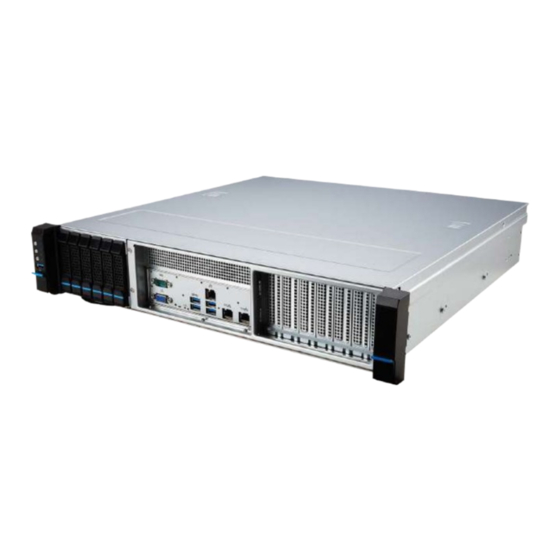
Page 6: System Overview
System Overview MS-S239 6 x 2.5” SATA Hot-Swap Drive Bays System Overview... - Page 7 System Power Button UID Button System Reset Button HDD Activity LED ! System Alarm LED NIC Link LED USB 2.0 Port This connector is provided for USB peripheral devices. (Speed up to 480 Mbps) ⚠ Important High-speed devices are recommended for USB 3.2 ports whereas low-speed devices, such as mouse or keyboard, are suggested to be plugged into the USB 2.0 ports.
- Page 8 10 GbE RJ45 Port The standard RJ45 LAN jack is provided for connection to the Local Area Network (LAN). You can connect a network cable to it. 1 GbE Status Description No link Link/ Activity Linked Yellow LINK/ACT SPEED Blinking Data activity 10 Mbps Speed LED 100 Mbps...
-
Page 9: System Specifications
System Specifications Model E2101 Dimensions 2U, 17.2”W (438mm) x 3.4”H (87mm) x 17.7”D (450mm) Processor Single AMD EPYC ™ 7002/ 7003 Series Processors, up to 64C, TDP 225W Memory ∙ 8 x DDR4 Max 2933/ 3200 Mhz - RDIMM/ LRDIMM/ 3DS up to 2TB Networking ∙... -
Page 10: Motherboard Connector
Motherboard Connector JPWR1, JPWR2, JPWR3: Power Connector JPWR1 P12V P12V JPWR2 +12V +12V +12V +12V P3V3 P3V3 P3V3 -12V PS-ON# JPWR3 ATX_POK 5VSB P12V P12V P3V3 Motherboard Connector... - Page 11 CPU_FAN1: CPU Fan Power Connectors SYS_FAN1 ~ SYS_FAN6: System Fan Power Connectors JFP1: Front Panel Header JCHASSIS1: Chassis Intrusion Header JVGA1:VGA Box Header JFP1 CPU_FAN1 SYS_FAN1~6 PWR_LED+ FP_PWR FAN POWER SYS_ID_LED+ FAN SENSE FAN_PWM PWR_LED- SYS_ID_LED- HDD_ACT_LED+ SYS_FAULT_LED1- HDD_ACT_LED- SYS_FAULT_LED2- JCI1 PWR_BTN NIC#1_ACT_LED+...
- Page 12 JPMBUS1: PMBUS Box Header IPMB1: IPMB Box Header SOC_SMB: SOC SMB Box Header JCOM2: COM Port Header SGPIO Box Header: JSGPIO1 JPMBUS1 JCOM2 SMB_IPMB_STBY_LVC3_SCL CONB_DCD CONB_RXD SMB_IPMB_STBY_LVC3_SDA CONB_TXD CONB_DTR PMB_ALERT CONB_DSR CONB_RTS CONB_CTS P3V3_AUX CONB_RI JSGPIO1 JIPMB1 SMB_IPMB_DAT SGPIO_BMC_CLK 2_5HD_SEL SGPIO_BMC_LD_N RST_PLTRST_N SMB_IPMB_CLK...
- Page 13 BP_I2C_1: Backplane I2C Header JUSB1: USB 3.2 Gen 1 Box Header JTPM1: TPM Module Box Header BP_I2C_1 VDD_5_DUAL BP_I2C_CLK1 BP_I2C_DAT1 P5V_AUX_USB_BP0 USB3_HEADER_P0_ESD_RX USB3_HEADER_P0_ESD_RXP USB3_HEADER_P0_ESD_TXN USB3_HEADER_P0_ESD_TXP USB2_P0_ESD_DN JFUSB1 USB2_P0_ESD_DP USB2_P1_ESD_DP USB2_P1_ESD_DN USB3_HEADER_P1_ESD_TXP USB3_HEADER_P1_ESD_TXN USB3_HEADER_P1_ESD_RXP USB3_HEADER_P1_ESD_RXN P5V_AUX_USB_BP5 P0_XLTR_LS_SPI_CS_L P0_RSMRST_LS_L VDD_33_DUAL P0_XLTR_LS_SPI_CLK P0_ROM_SPI_WP_L JTPM1 P0_ROM_SPI_HOLD_L P0_XLTR_LS_SPI_MISO...
-
Page 14: Motherboard Jumper
Motherboard Jumper Jumper Name Default Setting Description 1-2: BMC Control RTC_CLR2_1 2-3: Bypass BMC Control (default) Motherboard Jumper... -
Page 15: Getting Started
Getting Started ⚠ Important All information is subject to change without prior notice. Necessary Tools Screwdriver Pliers Tweezers Anti-Static Gloves Safety Precautions The following precautions should be observed while handling the system: ∙ Place the system on a flat and stable surface. ∙... -
Page 16: System Setup
System Setup ⚠ Important Before removing or installing any components, make sure the system is not turned on or connected to the power. When installing the CPU, make sure that you install cooler to prevent overheating. If you do not have the CPU cooler, consult your dealer before turning on the computer. ∙... - Page 17 ⚠ Important While replacing the CPU, always turn off the power supply or unplug the power ∙ supply’s power cord from the grounded outlet first to ensure the safety of CPU. Overheating will seriously damage the CPU and system. Always make sure the ∙...
-
Page 18: Memory
Memory 1. Unlock the DIMM slot by flipping open its side clips. 2. Vertically insert the DIMM into the DIMM slot. The DIMM has an off-center notch at the bottom that will only allow it to fit one way into the DIMM slot. 3. -
Page 19: Supported Memory Population
Ch D Ch C Ch B Ch A Ch E Ch F Ch G Ch H AMD® EPYC™ Supported Memory Population Channel Chan D Chan C Chan B Chan A Chan E Chan F Chan G Chan H Number of DIMM Not Recommended Not Recommended Not Recommended... -
Page 20: Key M (Optional)
M.2 Key M (Optional) ⚽ Video Demonstration Watch the video to learn how to Install M.2 SSD. 1. Loosen the M.2 riser screw from the motherboard. 2. Move and fasten the M.2 riser screw to the appropriate location according your M.2 SSD size. -
Page 21: Air Cooler Module
Air Cooler Module 1. Place the system on a flat and steady surface. Locate screws on both sides, and remove it to uncover the system. 2. Lift the cover up carefully, and set the cover and screws aside for later use. 3. - Page 22 4. Place the air cooler module on top of the CPU with the airflow intake from the I/O side and the airflow exhaust from the fans side. 5. Tighten all screws in diagonal sequences to secure the it to the motherboard. Torque: 10~11 kgf·cm = 0.98~1.078 N·m...
- Page 23 6. Connect the cooler cable to the fan power connector on the motherboard. 7. Place the system cover back to the chassis and fasten the screws. Follow the above procedures in reverse order to install air cooler module. ∙ Air Cooler Module...
- Page 24 EPS.MSI.COM MSI.COM...
Need help?
Do you have a question about the E2101 and is the answer not in the manual?
Questions and answers