Table of Contents
Advertisement
Quick Links
Advertisement
Table of Contents

Related Manuals for MSI S2206


Summary of Contents for MSI S2206
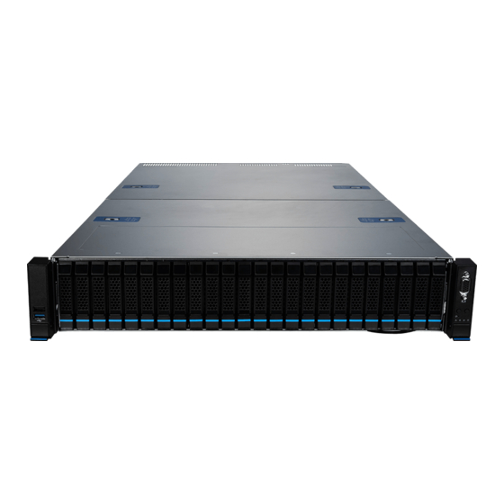
- Page 1 S2206 (2U12) MS-S312 Server System User Guide...
-
Page 2: Table Of Contents
Contents Regulatory Notices ....................... 4 Safety Information ......................6 System Specifications ....................7 System Overview ......................9 Block Diagram ......................12 System Storage Topology ..................13 System LED Indicators ....................14 Motherboard Overview ....................15 Motherboard Connectors ..................16 Storage Connectors ....................16 Expansion Slots .................... - Page 3 Memory ........................38 Recommended Memory Population ..............39 Installing Memory Modules .................. 40 M.2 M Key ........................41 Installing M.2 M Key ..................... 41 PCIe Add-in Card ......................42 Installing PCIe Add-in Card .................. 42 Installing Riser Card Assembly ................43 Connecting GPGPU Card ..................
-
Page 4: Regulatory Notices
Chemical Substances Information In compliance with chemical substances regulations, such as the EU REACH Regulation (Regulation EC No. 1907/2006 of the European Parliament and the Council), MSI provides the information of chemical substances in products at: https://csr.msi.com/global/index CE Conformity Hereby, Micro-Star International CO., LTD declares that this device is in compliance with the essential safety requirements and other relevant provisions set out in the European Directive. - Page 5 Copyright and Trademarks Notice Copyright © Micro-Star Int’l Co., Ltd. All rights reserved. The MSI logo used is a registered trademark of Micro-Star Int’l Co., Ltd. All other marks and names mentioned may be trademarks of their respective owners. No warranty as to accuracy or completeness is expressed or implied.
-
Page 6: Safety Information
Safety Information ∙ Always read the safety instructions carefully. ∙ Keep this User’s Manual for future reference. ∙ Keep this equipment away from humidity. ∙ Lay this equipment on a reliable flat surface before setting it up. ∙ The openings on the enclosure are for air convection hence protects the equipment from overheating. -
Page 7: System Specifications
System Specifications SKUs S2206-02 S2206-05-10G Form factor Dimensions 438mm(17.2”) W x 87mm(3.4”) H x 770mm(30.3”)D Processor Dual AMD EPYC™ 9004 Series processors with AMD 3D V-Cache™ Technology, TDP up to 360W Socket 2 x AMD Socket SP5 ∙ 2 x GbE RJ45 ports ∙... - Page 8 SKUs S2206-02 S2206-05-10G 1 x TPM header (with SPI interface) Security TPM 2.0 ∙ 1 x GbE RJ45 Port (mgmt.) (Realtek® RTL8211FD-CG) ∙ 1 x MicroSD card slot (for BMC log) Server ∙ ASPEED AST2600 with AMI MegaRAC based firmware Management - Supports IPMI 2.0 and DMTF Redfish®...
-
Page 9: System Overview
System Overview 8 x 3.5”/2.5” SATA 4 x 3.5”/2.5” NVMe Hot-Swap Drive Bays Hot-Swap Drive Bays Riser #3 Riser #3 Riser #1 Riser #1 Riser #2 Riser #2 (S2206-02 only) System Overview... - Page 10 USB 2.0 Type-A Port This connector is provided for USB peripheral devices. (Speed up to 480 Mbps) ⚠ Important High-speed devices are recommended for USB 3.2 ports whereas low-speed devices, such as mouse or keyboard, are suggested to be plugged into the USB 2.0 ports.
- Page 11 GbE RJ45 Port (S2206-02 only) The standard RJ45 LAN jack is provided for connection to the Local Area Network (LAN). You can connect a network cable to it. Status Description No link Link/ Activity Linked Green Blinking Data activity LINK/ACT...
-
Page 12: Block Diagram
Block Diagram CPU0 CPU0 32 Gbps 6 x DIMM Slots DDR5 CH A~F DDR5 CH A~F 6 x DIMM Slots (1DPC) Socket SP5 (1DPC) Socket SP5 XGMI 16X CPU0_DIMM_A1 CPU1_DIMM_A1 CPU0_DIMM_F1 CPU1_DIMM_F1 XGMI 16X 6 x DIMM Slots DDR5 CH G~L XGMI 16X 6 x DIMM Slots DDR5 CH G~L... -
Page 13: System Storage Topology
System Storage Topology SATA #7 SATA #7 SATA #1 SATA #1 NVMe #2 NVMe #2 SATA #4 SATA #4 NVMe #3 NVMe #3 SATA #8 SATA #8 SATA #5 SATA #5 SATA #2 SATA #2 NVMe #1 NVMe #1 SATA #3 SATA #3 NVMe #4 NVMe #4... -
Page 14: System Led Indicators
System LED Indicators UID Button/ LED System Power Button/ LED System Reset Button M.2 Activity LED System Alarm LED NIC Link LED LED State Description System Power LED System power is on Blue System power is on ACPI S0 state System is sleeping Blinking System power is off... -
Page 15: Motherboard Overview
Motherboard Overview JVGA1 COM1 USB2 USB1 MLAN1 LAN2 LAN1 JUID_SEL1 BAT1 RISER2 JRTC_CLR1 SEG_LED1~4 RISER3 MSD1 BMC_HB_LED OCP1 JCHASSIS1 RISER1 JSPI_MUX1 RISER4 M2_1 M2_2 JBIOS_SYS1 JTPM1 JFP_VGA1 JSPI1 BMC_JTAG1 JSEL_BMC1 JBIOS_LOC1 BMC_F2 BMC_F1 JIPMB1 GPU_PWR5 JSATA_NVME_SW1 PSU_PWR2 PSU_PWR1 JMCIO4 JUSB1 HDD_PWR3 JSGPIO_PCH JMCIO3... -
Page 16: Motherboard Connectors
Motherboard Connectors Storage Connectors MSD1 M2_1 M2_2 JMCIO4 JMCIO3 JSLIM4X_1 JMCIO5 JMCIO2 JMCIO1 JMCIO6 Name Description JSLIM4X_1 PCIe 3.0 x4, 8GT/s PCIe 4.0 x4, 16GT/s (default) JMCIO1~4 SATA 3.0, 6Gb/s JMCIO5~6 PCIe 4.0 x8, 16GT/s M2_1~2 PCIe 3.0 x2, 8GT/s M2_1~2: M.2 Slots (M Key, PCIe 3.0 x2, 2280) The M.2 slot supports solid-state drive (SSD). - Page 17 JMCIO1~4: MCIO 4i Connectors These are right-angle 38-pin Mini Cool Edge IO (MCIO) connectors, which support PCIe 4.0 x4 16GT/s and SATA 3.0 6Gb/s interfaces. A JSATA_NVME_SW1 jumper can be used to switch signals between SATA and PCIe NVMe (default). RXP0 TXP0 RXN0...
- Page 18 JMCIO5~6: MCIO 8i Connectors These are vertical 74-pin Mini Cool Edge IO (MCIO) connectors, which support PCIe 4.0 x8 16GT/s interface RXP0 TXP0 RXN0 TXN0 RXP1 TXP1 RXN1 TXN1 I2C_CLK1 HP_INT_L1 I2C_DATA1 PCIe CLK_P1 PCIe_RST1 PCIe CLK_N1 PRSNT_N (NC) RXP2 TXP2 JMCIO5~6 RXN2...
- Page 19 JSLIM4X_1: Slimline SAS 4i Connector This is 38-pin Slimline SAS 4i connector, which support PCIe 3.0 x4 8GT/s interface RXP0 TXP0 RXN0 TXN0 RXP1 TXP1 RXN1 TXN1 JSLIM4V_1 I2C_CLK HP_INT_L I2C_DATA PCIe CLK_P PCIe_RST PCIe CLK_N PRSNT_N (NC) RXP2 TXP2 RXN2 TXN2 RXP3...
-
Page 20: Expansion Slots
Expansion Slots RISER1: PCIe 5.0 x 32 slot (from CPU0) RISER2: PCIe 5.0 x 32 slot (from CPU1) RISER3: PCIe 5.0 x 16 slot (from CPU1) RISER4: Fixed slot OCP1: OCP 3.0 SFF (PCIe 5.0 x16, from CPU0) RISER1~4: PCIe Expansion Slots The PCI Express(Peripheral Component Interconnect Express) slots support PCIe interface expansion cards. -
Page 21: Power Connectors
Power Connectors PSU_PWR1 PSU_PWR2 GPU_PWR1 HDD_PWR3 GPU_PWR2 GPU_PWR6 GPU_PWR3 GPU_PWR5 GPU_PWR4 HDD_PWR2 HDD_PWR1 PSU_PWR1~2: CRPS Power Connectors These CRPS (Common Redundant Power Supplies) connectors allow you to connect a power supply. To connect the power supply, ensure that the plug is inserted in the proper orientation and that the pins are aligned. - Page 22 HDD_PWR3: 4-Pin Rear HDD BP Power Connector This connector provides power output to HDDs on rear side. HDD_PWR3 P12V ⚠ Important Make sure that all power connectors are securely connected to the power supply to ensure stable operation of the motherboard. Motherboard Connectors...
-
Page 23: Cooling Connectors
Cooling Connectors CPU_FAN1 CPU_FAN2 F2U-1 F2U-2 F2U-3 F2U-4 F2-U5 F2U-6 F1U-1 F1U-2 F1U-3 F1U-4 F1U-5 F1U-6 F1U-7 F1U-8 F2U-1~6: 2U System Fan Connectors The fan power connectors support 2U system cooling fans. P12V F2U-1~6 FAN_TACH FAN_PWM FAN_FAULT F1U-1~8: 1U System Fan Connectors The fan power connectors support 1U system cooling fans. -
Page 24: Usb Connectors
USB Connectors JUSB1 JUSB2 JUSB1: USB 3.2 Gen 1 Type-A Port The USB (Universal Serial Bus) port is used for connecting USB devices JUSB1 such as keyboards, mice, or other compatible peripherals. It supports data transfer rates up to 5 Gbps and is backward-compatible with USB 2.0 devices. - Page 25 Other Connectors and Components JCHASSIS1: Chassis Intrusion Header This header connects to the chassis intrusion switch cable. If the chassis is opened, the chassis intrusion mechanism will be activated. The system will record this status and show a warning message on the screen. To clear the warning, you must enter the BIOS utility and clear the record.
- Page 26 JTPM1: SPI TPM Header This header connects to a TPM (Trusted Platform Module) module (optional). Please refer to the TPM security platform manual for more details. P3V3_AUX SPI_CPU0_3V3_CLK SPI_CPU0_3V3_MISO JTPM1 SPI_CPU0_3V3_MOSI SPI_TPM_CS_N IRQ_TPM_SPI_N P3V3_AUX TPM_RESET_N P3V3_AUX JTPM1 Motherboard Connectors...
- Page 27 JFP_VGA1: Front VGA Header The VGA header is provided for monitors. F_RED JFP_VGA1 F_GRN F_BLU F_VS F_HS F_DDCDAT SEL_FP_N F_DDCCLK F_VGA_5V JFP_VGA1 Motherboard Connectors...
- Page 28 FBP_I2C_1, RBP_I2C_1~2: I2C Headers I2C headers are used to connect to the System Management Bus (SMBus). FBP_I2C_1 is for front HDD backplane, and RBP_I2C_1~2 are for rear HDD backplanes. FBP_I2C_1 I2C_DAT RBP_I2C_1 RBP_I2C_2 I2C_CLK JSGPIO_PCH: Rear Side BP SGPIO Box Header JSGPIO_PCH SGPIO_SATA_CLOCK_RBP SGPIO_SATA_LOAD_RBP...
-
Page 29: Motherboard Jumpers
Motherboard Jumpers ⚠ Important Avoid adjusting jumpers when the system is on; it will damage the motherboard. JUID_SEL1 JRTC_CLR1 JSPI_MUX1 JSEL_BMC1 JSATA_NVME_SW1 Jumper Name Default Setting Description 1-2: BIOS1 & allows BMC to switch (default) JSPI_MUX1 2-3: BIOS2 (backup only, use when BIOS1 flash crashes) 1-2: BMC1 (default) JSEL_BMC1 2-3: BMC2... -
Page 30: Motherboard Leds
Motherboard LEDs BMC_HB_LED: BMC Heartbeat LED This LED indicates the BMC (Baseboard Management Controller) status. Status Description BMC is not activated BMC is functioning normally Blinking BMC_HB_LED SEG_LED1~4: Port 80 Edge LEDs The Port 80 Edge LEDs display progress and error codes during and after POST (Power-On Self Test). -
Page 31: Getting Started
Getting Started ⚠ Important All information is subject to change without prior notice. ∙ ∙ The system photos are provided for demonstration purposes only. The appearance and internal view of your system may vary depending on the model you purchased. Necessary Tools Screwdriver Pliers... -
Page 32: System Setup
System Setup ⚠ Important Before removing or installing any components, make sure the system is not turned on or connected to the power. Drive Bay Installing 3.5"/2.5" Storage Drive 1. Engage two embossed pins on the carrier into the side dimples on the 3.5” drive. For 2.5”... -
Page 33: System Cover
System Cover Removing System Cover 1. Remove the screws securing the system on both sides. 2. To remove the top cover panels, press down on the release latches on both sides and then slide them to the front or back side of the system. System Cover... -
Page 34: Cpu & Heatsink
CPU & Heatsink Use appropriate ground straps, gloves and ESD mats to protect yourself from electrostatic discharge (ESD) while installing the processor. CPU1 CPU0 ⚠ Important ∙ Overheating will seriously damage the CPU and system. Always make sure the cooling fan can work properly to protect the CPU from overheating. Make sure that you apply an even layer of thermal paste (or thermal tape) between the CPU and the heatsink to enhance heat dissipation. -
Page 35: Installing Cpu & Heatsink
Installing CPU & Heatsink ⚠ Important Images are for illustration purposes only; actual parts may vary. 1. Remove the screw on the top of the retention frame. 2. After removing the top screw, the spring-loaded retention frame will rise up. Hold it gently until it is fully open. - Page 36 4. Pull the external cap upward through the rail guides on the rail frame to remove it. 5. Grip the handle of the carrier frame and slide it downward with the flanges and the rail guides aligned. CPUs are shipped from the factory with pre-assembled carrier frames. ∙...
- Page 37 7. Push the retention frame downward and use a torque screwdriver to tighten the screw in the middle. Torque Screwdriver Settings Screw Head: Torx T20 Torque: 12.5-15 kgf·cm* *12.5-15 kgf·cm = 122.6~147 N·m = 10.9~13 lbf·in 8. For peak thermal performance, apply proper amount of thermal paste to the bottom center of the heatsink.
-
Page 38: Memory
Memory CPU1_DIMM_F1 CPU1_DIMM_E1 CPU1_DIMM_D1 CPU1_DIMM_C1 CPU1_DIMM_B1 CPU1_DIMM_A1 CPU1 CPU1_DIMM_G1 CPU1_DIMM_H1 CPU1_DIMM_I1 CPU1_DIMM_J1 CPU1_DIMM_K1 CPU1_DIMM_L1 CPU0_DIMM_F1 CPU0_DIMM_E1 CPU0_DIMM_D1 CPU0_DIMM_C1 CPU0_DIMM_B1 CPU0_DIMM_A1 CPU0 CPU0_DIMM_G1 CPU0_DIMM_H1 CPU0_DIMM_I1 CPU0_DIMM_J1 CPU0_DIMM_K1 CPU0_DIMM_L1 Memory... -
Page 39: Recommended Memory Population
Recommended Memory Population D C B D C B CPU1 CPU0 1 CPU Channel Qty. of DDR5 2 CPUs Channel Qty. of DDR5 CPU1 CPU0 CPU1 CPU0 CPU1 CPU0 CPU1 CPU0 CPU1 CPU0 CPU1 CPU0 CPU1 CPU0 CPU1 CPU0 “V” indicates DIMMs are populated with DDR5. ⚠... -
Page 40: Installing Memory Modules
Installing Memory Modules 1. Open the side clips to unlock the DIMM slot. 2. Insert the DIMM vertically into the slot, ensuring that the off-center notch at the bottom aligns with the slot. 3. Push the DIMM firmly into the slot until it clicks and the side clips automatically close. -
Page 41: M.2 M Key
M.2 M Key Installing M.2 M Key ⚽ Video Demonstration Watch the video to learn how to Install M.2 SSD. 1. Insert your M.2 SSD into the M.2 slot at a 30-degree angle. 30° Supplied M.2 screw 2. Secure the M.2 SSD in place with the supplied M.2 screw. -
Page 42: Pcie Add-In Card
PCIe Add-in Card Installing PCIe Add-in Card 1. Loosen the screws on the riser bracket to remove the filler panels. 2. Align the PCIe add-in card with the connector on the riser card, and insert it until it is fully seated. 3. -
Page 43: Installing Riser Card Assembly
Installing Riser Card Assembly 1. Make sure the key slots on the rear edge of the riser card assembly are aligned with the mounting pins on the rear edge of the system (indicated by the red circle in the image below). 2. -
Page 44: Connecting Gpgpu Card
Connecting GPGPU Card Connect cable to the 8-pin power connectors on the GPGPU card and the GPU power connecor on the system board. GPGPU# Riser Slot GPGPU Power Connector Location on the System Board GPGPU#1 RISER1 GPU_PWR4~5 GPGPU#2 RISER2 GPU_PWR2, 6 ⚠... -
Page 45: System Fan
System Fan The server system is equipped with six 60 x 60 x 38mm hot-swappable system fans that provide primary airflow to maintain optimal cooling and prevent overheating. The fan features include: ∙ Tachometer on each fan allows BMC to monitor the system’s status in real-time. ∙... -
Page 46: Installing 2U Fan Cage
Installing 2U Fan Cage 1. Press the release tabs and lift the fan to remove it from the cage. Ensure all cables are clear of the fan cage installation area before proceeding. ∙ 2. Align the guiding rails and lower the fan cage onto the system’s base. Then push down the latches to lock it into place. -
Page 47: Air Duct
Air Duct The server system offers two air duct options: a pre-installed GPGPU air duct and a standard air duct available as an accessory. Installing Air Duct ⚠ Important The type of air duct used with the system depends on the processor heatsink and ∙... -
Page 48: Power Supply Unit (Psu)
Power Supply Unit (PSU) The server system supports two power supplies that can be easily inserted and removed from the rear side of the system without the need for tools. ⚠ Important Both power supplies must be identical and both power cords should be connected. ∙... -
Page 49: Cable Routing
Cable Routing ⚠ Important Please remove the fan cage before routing cables. 8-pin to 8-pin Power Cable HDD_PWR2 HDD_PWR1 I2C Cable FBP_I2C_1 Cable Routing... -
Page 50: Mcio 4I To Slimlinesas 4I Cable
MCIO 4i to SlimlineSAS 4i Cable MCIO 8i to SlimlineSAS 4i Cable MCIO 8i (with white label) JMCIO5 JMCIO6 Cable Routing... -
Page 51: Slide Rail
Slide Rail ⚠ Important The pre-installed screws on the outer rail bracket are intended only for square rack holes. For round holes, please switch to the “7.1 round hole screw”. 9.5 Square Hole Screw (pre-installed) 7.1 Round Hole Screw Disassembling Slide Rail Slide the release tab forward to separate the inner rail from the bracket. -
Page 52: Installing Inner Rail To System
Installing Inner Rail to System 1. Align the standoffs on the side of the system with the hole on the inner rail, then pull the inner rail backwards till it locks into place. 2. Tighten the screw to secure the inner rail. 3. -
Page 53: Retracting Outer Rail Bracket
Retracting Outer Rail Bracket Pull the latch downward to slide the middle rail back to the outer rail bracket. Middle Rail Attaching Outer Rail Bracket to Rack Frame Slide Rail... -
Page 54: Installing System Into Rack
Installing System into Rack 1. Pull out the middle rails till it fully extended. 2. Engage the inner rails of the system to the middle rails, then push the system forward until it stops. 3. Push the system into the rack by sliding the two-way release tabs forward or backward. 4. -
Page 55: Detaching Outer Rail Bracket From Rack Frame
Detaching Outer Rail Bracket from Rack Frame Detaching Inner Rail from System Slide Rail... - Page 56 EPS.MSI.COM MSI.COM...
Need help?
Do you have a question about the S2206 and is the answer not in the manual?
Questions and answers