Table of Contents
Advertisement
Quick Links
Advertisement
Table of Contents

Related Manuals for MSI S1102-01


Summary of Contents for MSI S1102-01
- Page 1 S1102-01 MS-S336 Server System User Guide...
-
Page 2: Table Of Contents
Contents Regulatory Notices ....................... 4 Safety Information ......................6 System Specifications ....................7 System Overview ......................8 System LED Indicators ....................11 Motherboard Overview ....................12 Motherboard Connectors ..................13 Storage Connectors ....................13 SATA1~8: SATA 3.0 6Gb/s Ports ..............13 M2_1, M2_2: M.2 Slots (M Key, PCIe 4.0, 22110/ 2280) ......... - Page 3 FP_I2C_1, RBP_I2C_1, RBP_I2C_2: I2C Box Header ........24 JCOM1: COM Port Box Header ..............24 Motherboard Jumpers ....................25 Getting Started ......................26 Necessary Tools ....................26 Safety Precautions ....................26 System Setup ......................27 Drive Bay ........................27 Installing 3.5"/2.5" Storage Drive ................. 27 System Cover ......................
-
Page 4: Regulatory Notices
Chemical Substances Information In compliance with chemical substances regulations, such as the EU REACH Regulation (Regulation EC No. 1907/2006 of the European Parliament and the Council), MSI provides the information of chemical substances in products at: https://csr.msi.com/global/index CE Conformity Hereby, Micro-Star International CO., LTD declares that this device is in compliance with the essential safety requirements and other relevant provisions set out in the European Directive. - Page 5 Copyright and Trademarks Notice Copyright © Micro-Star Int’l Co., Ltd. All rights reserved. The MSI logo used is a registered trademark of Micro-Star Int’l Co., Ltd. All other marks and names mentioned may be trademarks of their respective owners. No warranty as to accuracy or completeness is expressed or implied.
-
Page 6: Safety Information
Safety Information ∙ Always read the safety instructions carefully. ∙ Keep this User’s Manual for future reference. ∙ Keep this equipment away from humidity. ∙ Lay this equipment on a reliable flat surface before setting it up. ∙ The openings on the enclosure are for air convection hence protects the equipment from overheating. -
Page 7: System Specifications
System Specifications Model S1102-01 Form Factor Dimensions 1.71”H (43.5mm) x 17.26”W (438.5mm) x 21.56”D (547.6mm) ∙ 1 x AMD® Ryzen™ 7000 series Processors, TDP 105W Processor - Processor socket AM5 Chipset AMD B-class Chipset ∙ 4 x DIMM slots Memory... -
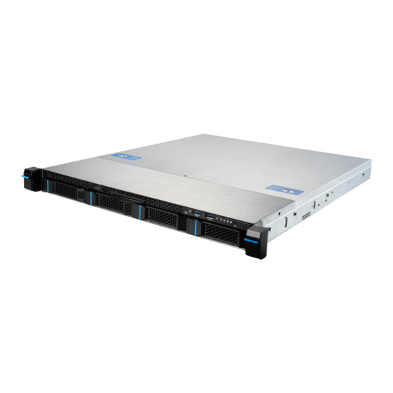
Page 8: System Overview
System Overview 4 x 2.5/ 3.5” SATA Hot-Swap Drive Bays System Overview... - Page 9 UID Button The UID (Unit Identification) button help users identify and locate a system, especially in high-density rack environments. USB 3.2 Gen 1 Port This connector is provided for USB peripheral devices. (Speed up to 5 Gbps) ! System Status LED HDD Activity LED Power LED LAN Activity LED...
- Page 10 GbE RJ45 Port The standard RJ45 LAN jack is provided for connection to the Local Area Network (LAN). You can connect a network cable to it. Status Description JLANCONN1 (U) No link Link/ Activity Linked Green LINK/ACT SPEED Blinking Data activity 10 Mbps Speed LED 100 Mbps...
-
Page 11: System Led Indicators
System LED Indicators System Status LED LAN Activity LED UID LED Power LED HDD Activity LED LED State Description System power is on Blue System power is on ACPI S0 state System is sleeping Blinking Power LED System power is off System power is on ACPI S4, S5 state Blue Identify active via command or button... -
Page 12: Motherboard Overview
Motherboard Overview BAT1 Motherboard Overview... -
Page 13: Motherboard Connectors
Motherboard Connectors Storage Connectors SATA1~8: SATA 3.0 6Gb/s Ports These connectors are SATA 6Gb/s interface ports, it can connect to SATA devices. SATA4 SATA3 SATA2 SATA1 SATA3-1 ⚠ Important ∙ Please do not fold the SATA cable at a 90-degree angle. Data loss may result during transmission otherwise. -
Page 14: M2_1, M2_2: M.2 Slots (M Key, Pcie 4.0, 22110/ 2280)
M2_1, M2_2: M.2 Slots (M Key, PCIe 4.0, 22110/ 2280) The M.2 slot supports solid-state drive (SSD). For Installation procedure, please refer to “System Setup > M.2 M Key”. M2_1* M2_2 *M2_1: The M2_1 and PCIE_2 slots cannot operate simultaneously. You can use the JSEL_M1 jumper to select which one to enable. -
Page 15: Expansion Slots
Expansion Slots PCIE_2*: PCIe 4.0 x 8 slot (Gen 4 x 4 signal from CPU) PCIE_1: PCIe 5.0 x 16 slot (Gen 5 x 16 signal from CPU) *PCIE_2: The PCIE_2 and M2_1 slots cannot operate simultaneously. You can use the JSEL_M1 jumper to select which one to enable. -
Page 16: Power Connectors
Power Connectors JPWR1 JPWR2 JSDOMPWR1 SATAPWR1 SATAPWR1: SATA Power Connector This connector is used to provide power to SATA devices. SATAPWR1 P12V JPWR1: 12V Power Connector This connector allows you to connect an ATX power supply. JPWR1 P12V P12V P12V P12V Motherboard Connectors... -
Page 17: Jpwr2: Main Power Connector
JPWR2: Main Power Connector This connector allows you to connect an ATX power supply. +3.3V +3.3V PWR OK 5VSB +12V +12V +3.3V JPWR2 +3.3V -12V PS-ON# JSDOMPWR1: SATA DOM Power Connector This connector is used to provide power to SATA DOM devices. JSDOMPWR1 ⚠... -
Page 18: Cooling Connectors
Cooling Connectors FAN1 ~ 8, PUMP1: Fan Power Connectors The fan power connector supports system cooling fans with +12V. When connecting the wire to the connectors, always note that the red wire is the positive and should be connected to the +12V; the black wire is Ground and should be connected to GND. FAN_TACH FAN1~8 P12V... -
Page 19: Other Connectors
Other Connectors JFP1: Front Panel Connector The front panel connector is provided for electrical connection to the front panel switches and LEDs. PWR_LED+ FP_PWR SYS_ID_LED+ PWR_LED- SYS_ID_LED- HDD_ACT_LED+ SYS_FAULT_LED1- HDD_ACT_LED- SYS_FAULT_LED2- PWR_BTN NIC#1_ACT_LED+ JFP1 PWR_BTN_GND NIC#1_ACT_LED- RST_BTN SMB_SDA RST_BTN_GND SMB_SCL SYS_ID_BTN CHASSIS_INTRUSION WIRE_TEMP_SENSOR... -
Page 20: Jtpm1: Spi Tpm Module Box Header
JTPM1: SPI TPM Module Box Header This connector connects to a TPM (Trusted Platform Module) (optional). Please refer to the TPM security platform manual for more details. SPI_LOC_ROM_CS_N CPU_RSMEST_L PVDD_P1V8_AUX SPI_LOC_ROM_CLK SPI_CPU0_WP_L JTPM1 SPI_CPU0_HOLD_L SPI_LOC_ROM_MISO SPI_LOC_ROM_MOSI CPU_SPI_TPM_CS_N PVDD_P1V8_AUX CPU_TPM_SPI_IRQ_N PVDD_P1V8_AUX TPM_RESET_N PVDD_P1V8_AUX JTPM1... -
Page 21: Jgpio1: Gpio Header
JGPIO1: GPIO Header This connector is provided for the General-Purpose Input/Output (GPIO) peripheral module. USER_GPIO0 USER_GPIO1 USER_GPIO2 USER_GPIO3 JGPIO1 USER_GPIO4 USER_GPIO5 USER_GPIO6 USER_GPIO7 No pin JPMBUS1: PMBUS Box Header Power Management Bus (PMBus) is a variant of the System Management Bus (SMBus) which is targeted at digital management of power supplies. -
Page 22: Jchassis: Chassis Intrusion Header
JCHASSIS: Chassis Intrusion Header This connector connects to the chassis intrusion switch cable. If the chassis is opened, the chassis intrusion mechanism will be activated. The system will record this status and show a warning message on the screen. To clear the warning, you must enter the BIOS utility and clear the record. -
Page 23: Jusb1: Usb 3.2 Port Box Header
JUSB1: USB 3.2 Port Box Header This port is backward-compatible with USB 2.0 devices and supports data transfer rate up to 5 Gbit/s (SuperSpeed). USB_VCC1 USB3_ESD_RX4N USB3_ESD_RX4P USB3_ESD_TX4N USB3_ESD_RX4P USB3_ESD_DN8 USB3_ESD_DP8 JUSB1 USB2_ESD_DP9 USB2_ESD_DN9 USB3_ESD_TX5P USB3_ESD_TX5N USB3_ESD_RX5P USB3_ESD_RX5N USB_VCC2 No Pin JUSB2: USB 2.0 Type-A Connector JUSB2 The USB (Universal Serial Bus) port is for attaching USB devices such... -
Page 24: Fp_I2C_1, Rbp_I2C_1, Rbp_I2C_2: I2C Box Header
FP_I2C_1, RBP_I2C_1, RBP_I2C_2: I2C Box Header I2C connectors are used to connect to the System Management Bus (SMBus). FBP_I2C_1 is for front HDD backplane, and RBP_I2C_1, RBP_I2C_2 are for rear HDD backplanes. I2C_CLK FP_I2C_1 RBP_I2C_1 RBP_I2C_2 I2C_DAT JCOM1: COM Port Box Header This connector is a 16550A high speed communications port that sends/receives 16 bytes FIFOs. -
Page 25: Motherboard Jumpers
Motherboard Jumpers ⚠ Important Avoid adjusting jumpers when the system is on; it will damage the motherboard. JSEL_M1 JSEL_BMC1 Jumper Name Default Setting Description 1-2: M.2_1 enabled, PCIE_2 disabled (Default) JSEL_M1 2-3: PCIE_2 enabled, M.2_1 disabled 1-2: Using CPU (Default) JSEL_BMC1 2-3: Using BMC Motherboard Jumpers... -
Page 26: Getting Started
Getting Started ⚠ Important All information is subject to change without prior notice. ∙ ∙ The system photos are provided for demonstration purposes only. The appearance and internal view of your system may vary depending on the model you purchased. Necessary Tools Screwdriver Pliers... -
Page 27: System Setup
System Setup ⚠ Important Before removing or installing any components, make sure the system is not turned on or connected to the power. Drive Bay Installing 3.5"/2.5" Storage Drive 1. Engage two embossed pins on the carrier into the side dimples on the 3.5” drive. For 2.5”... -
Page 28: System Cover
System Cover Removing System Cover 1. Loosen and remove the screws securing the system on both sides and the top. 2. Press down on the release latches on both sides of the rear top cover, then slide it towards the back of the system to remove it. 3. -
Page 29: Cpu & Heatsink
CPU & Heatsink Use appropriate ground straps, gloves and ESD mats to protect yourself from electrostatic discharge (ESD) while installing the processor. ⚠ Important Overheating will seriously damage the CPU and system. Always make sure the ∙ cooling fan can work properly to protect the CPU from overheating. Make sure that you apply an even layer of thermal paste (or thermal tape) between the CPU and the heatsink to enhance heat dissipation. -
Page 30: Installing Cpu & Heatsink
Installing CPU & Heatsink ⚠ Important Images are for illustration purposes only; actual parts may vary. CPU & Heatsink... -
Page 31: Memory
Memory DIMMA1 DIMMB1 Channel A Channel B DIMMA2 DIMMB2 Recommended Memory Population Quantity of DIMMs DIMMA1 Channel A DIMMA2 DIMMB1 Channel B DIMMB2 **“V” indicates a populated DIMM slot. ** ⚠ Important ∙ Only support UDIMM. There should be at least 1 DDR5 DIMM populated. ∙... -
Page 32: Installing Memory Modules
Installing Memory Modules 1. Open the side clips to unlock the DIMM slot. 2. Insert the DIMM vertically into the slot, ensuring that the off-center notch at the bottom aligns with the slot. 3. Push the DIMM firmly into the slot until it clicks and the side clips automatically close. -
Page 33: M.2 M Key
M.2 M Key Installing M.2 M Key ⚽ Video Demonstration Watch the video to learn how to Install M.2 SSD. 1. Loosen the M.2 riser screw from the motherboard. 2. Move and fasten the M.2 riser screw to the appropriate location according your M.2 SSD size. -
Page 34: Slide Rail
Slide Rail ⚠ Important The pre-installed screws on the outer rail bracket are intended only for square rack holes. For round holes, please switch to the “7.1 round hole screw”. 9.5 Square Hole Screw (pre-installed) 7.1 Round Hole Screw Disassembling Slide Rail Slide the release tab forward to separate the inner rail from the bracket. -
Page 35: Installing Inner Rail To System
Installing Inner Rail to System 1. Align the standoffs on the side of the system with the hole on the inner rail, then pull the inner rail backwards till it locks into place. 2. Tighten the screw to secure the inner rail. 3. -
Page 36: Retracting Outer Rail Bracket
Retracting Outer Rail Bracket Pull the latch downward to slide the middle rail back to the outer rail bracket. Middle Rail Attaching Outer Rail Bracket to Rack Frame Slide Rail... -
Page 37: Installing System Into Rack
Installing System into Rack 1. Pull out the middle rails till it fully extended. 2. Engage the inner rails of the system to the middle rails, then push the system forward until it stops. 3. Push the system into the rack by sliding the two-way release tabs forward or backward. -
Page 38: Detaching Outer Rail Bracket From Rack Frame
Detaching Outer Rail Bracket from Rack Frame Detaching Inner Rail from System Slide Rail... - Page 39 EPS.MSI.COM MSI.COM...
Need help?
Do you have a question about the S1102-01 and is the answer not in the manual?
Questions and answers